

Recent progress in the functionalization of atomic force microscope ...
Recent progress in the functionalization of atomic force microscope ...
Recent progress in the functionalization of atomic force microscope ...

Create successful ePaper yourself
Turn your PDF publications into a flip-book with our unique Google optimized e-Paper software.
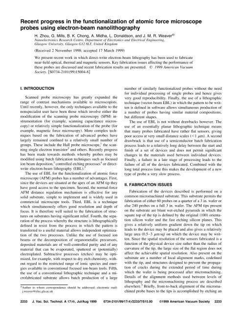
2236 Zhou et al.: <strong>Recent</strong> <strong>progress</strong> <strong>in</strong> <strong>the</strong> <strong>functionalization</strong> <strong>of</strong> AFM probes 2236FIG. 4. a Probe hav<strong>in</strong>g a sharp end, formed by dry etch<strong>in</strong>g <strong>the</strong> siliconnitride cantilever us<strong>in</strong>g a mask that extends only part <strong>of</strong> <strong>the</strong> way to <strong>the</strong> top<strong>of</strong> <strong>the</strong> pyramidal AFM tip. The sensor wire runs around <strong>the</strong> edge <strong>of</strong> <strong>the</strong>released probe, and is self-aligned to <strong>the</strong> edge s<strong>in</strong>ce excess metal disappearswhen <strong>the</strong> probe is released. b Thermocouple us<strong>in</strong>g double self-alignmentso that <strong>the</strong> size <strong>of</strong> <strong>the</strong> junction is limited by <strong>the</strong> hole beh<strong>in</strong>d <strong>the</strong> apex <strong>of</strong> <strong>the</strong>tip and <strong>the</strong> junction is self-aligned to <strong>the</strong> end <strong>of</strong> <strong>the</strong> tip as before. The probeis shown before <strong>the</strong> silicon substrate has been removed by a f<strong>in</strong>al wet etchprocess. c Double self-aligned <strong>the</strong>rmal resistor probe fabricated us<strong>in</strong>g <strong>the</strong>same method as <strong>the</strong> <strong>the</strong>rmocouple <strong>in</strong> b. The probe is shown after release.vantages. First, <strong>the</strong>y must be made <strong>in</strong>dividually, which istime consum<strong>in</strong>g and results <strong>in</strong> lack <strong>of</strong> reproducibility betweenprobes. Second, if a fiber is to be pulled <strong>in</strong> such a waythat <strong>the</strong> aperture is small, it is hard to prevent <strong>the</strong> taper angleat <strong>the</strong> end <strong>of</strong> <strong>the</strong> fiber from be<strong>in</strong>g ra<strong>the</strong>r shallow. The effect<strong>of</strong> this is that such probes lose a significant amount <strong>of</strong> <strong>the</strong>light <strong>in</strong> <strong>the</strong> cut<strong>of</strong>f metallic optical wave guide lead<strong>in</strong>g up to<strong>the</strong> aperture, as well as suffer<strong>in</strong>g <strong>the</strong> large losses associatedwith <strong>the</strong> aperture itself. F<strong>in</strong>ally, <strong>the</strong> fiber is ra<strong>the</strong>r stiff alongits length, so that <strong>force</strong> regulation must be accomplished by<strong>the</strong> use <strong>of</strong> shear-<strong>force</strong> regulation ra<strong>the</strong>r than by measurement<strong>of</strong> <strong>the</strong> deflection <strong>of</strong> a cantilever, which is more reliable. Thisobjection has been overcome to some extent by <strong>the</strong> use <strong>of</strong> abent fiber probe.More recently SNOM probes based on <strong>the</strong> use <strong>of</strong> micromach<strong>in</strong>edAFM probes have been realized. 20,21 EBL probe<strong>functionalization</strong> technology is well suited to <strong>the</strong> production<strong>of</strong> such probes. The process which has been adopted to date<strong>in</strong>volves <strong>the</strong> def<strong>in</strong>ition <strong>of</strong> a simple physical hole at <strong>the</strong> apex<strong>of</strong> <strong>the</strong> AFM probe by use <strong>of</strong> dry etch<strong>in</strong>g. 22 After release <strong>the</strong>entire probe, <strong>in</strong>clud<strong>in</strong>g <strong>the</strong> aperture, is coated with alum<strong>in</strong>umus<strong>in</strong>g a vacuum evaporator. Previous attempts to fabricatesuch probes us<strong>in</strong>g a palladium layer <strong>in</strong> which an aperturewas def<strong>in</strong>ed before release 5 were unsuccessful due to stresses<strong>in</strong> <strong>the</strong> ra<strong>the</strong>r thick Pd layer which were necessary for adequatescreen<strong>in</strong>g. A particular problem with this technique,however, is that <strong>the</strong> etch<strong>in</strong>g <strong>of</strong> a small hole through a siliconnitride layer that is thick enough to act as an adequate AFMprobe is difficult. For this reason, <strong>the</strong> silicon nitride around<strong>the</strong> tip is first th<strong>in</strong>ned from approximately 500 nm <strong>in</strong> thicknessto some 200 nm before aperture def<strong>in</strong>ition <strong>the</strong> ovalshape is approx 50 m across around <strong>the</strong> pyramid <strong>in</strong> Fig.J. Vac. Sci. Technol. A, Vol. 17, No. 4, Jul/Aug 1999
2237 Zhou et al.: <strong>Recent</strong> <strong>progress</strong> <strong>in</strong> <strong>the</strong> <strong>functionalization</strong> <strong>of</strong> AFM probes 2237FIG. 5. a Overview <strong>of</strong> a SNOM probe with a large aperture. The cantilever shape has been extended around <strong>the</strong> base <strong>of</strong> <strong>the</strong> pyramid to form a shield aga<strong>in</strong>stscattered light. The silicon nitride over <strong>the</strong> pyramidal tip has been th<strong>in</strong>ned to enable <strong>the</strong> aperture which is narrow to be etched all <strong>the</strong> way through. b Apex<strong>of</strong> a pyramid show<strong>in</strong>g a 150 nm diam SNOM aperure. c Effect <strong>of</strong> metallization granularity on <strong>the</strong> aperture shape. The aperture is seen to be rough on <strong>the</strong>scale <strong>of</strong> <strong>the</strong> gra<strong>in</strong> size, approximately 50 nm. Note <strong>the</strong> smooth shape <strong>of</strong> <strong>the</strong> underly<strong>in</strong>g silicon nitride substrate. d Somewhat smoo<strong>the</strong>r aperture pr<strong>of</strong>ileresult<strong>in</strong>g from <strong>the</strong> use <strong>of</strong> a cladd<strong>in</strong>g metal conta<strong>in</strong><strong>in</strong>g 5% w/w <strong>of</strong> copper.5a. S<strong>in</strong>ce light scatter<strong>in</strong>g around <strong>the</strong> probe was also foundto be troublesome, <strong>the</strong> cantilever has been extended for somedistance to form a screen around <strong>the</strong> probe. Such probes havebeen successfully scanned without <strong>force</strong> feedback for extendedperiods. Due to <strong>the</strong>ir low vertical stiffness and <strong>the</strong>large size <strong>of</strong> <strong>the</strong> probe apex region <strong>the</strong> local <strong>force</strong> on any part<strong>of</strong> <strong>the</strong> probe is low. Wear on <strong>the</strong> probe or on <strong>the</strong> substrateusually GaAs has <strong>the</strong>refore been found to be reduced to acompletely <strong>in</strong>significant level regardless <strong>of</strong> <strong>the</strong> external <strong>force</strong>applied to <strong>the</strong> probe. This significantly simplifies operation<strong>of</strong> <strong>the</strong> SNOM <strong>microscope</strong>, s<strong>in</strong>ce deflection measurement systemsgenerally based on bright optical sources such as diodelasers are not required. Due to <strong>the</strong> lack <strong>of</strong> any cut<strong>of</strong>f region<strong>in</strong> front <strong>of</strong> <strong>the</strong> probe aperture itself, measurements <strong>of</strong> totallight throughput for a 150 nm aperture Fig. 5b <strong>in</strong> red light633 nm <strong>of</strong> approximately one part <strong>in</strong> 10 3 has been rout<strong>in</strong>elyobta<strong>in</strong>ed. It should be noted that <strong>the</strong>se throughputs were obta<strong>in</strong>ed<strong>in</strong> a simple confocal transmission system hav<strong>in</strong>g illum<strong>in</strong>ationand collection optics operat<strong>in</strong>g at approximate numericalapertures NAs <strong>of</strong> 0.2–0.3. The SNOM probe itselfis capable <strong>of</strong> accommodat<strong>in</strong>g an illum<strong>in</strong>at<strong>in</strong>g beam <strong>of</strong> 0.55NA, which would lead to approximate quadrupl<strong>in</strong>g <strong>of</strong> <strong>the</strong>illum<strong>in</strong>at<strong>in</strong>g <strong>in</strong>tensity at <strong>the</strong> aperture.The limitation on resolution <strong>of</strong> <strong>the</strong> probes is def<strong>in</strong>ed by<strong>the</strong> granularity <strong>of</strong> <strong>the</strong> coat<strong>in</strong>g metal 99.999% pure alum<strong>in</strong>um.As may be seen from Fig. 5c, <strong>the</strong> aperture is roughJVST A - Vacuum, Surfaces, and Films
2238 Zhou et al.: <strong>Recent</strong> <strong>progress</strong> <strong>in</strong> <strong>the</strong> <strong>functionalization</strong> <strong>of</strong> AFM probes 2238FIG. 6. a 100 nm junction bismuth Hall probe magnetometer fabricated on a silicon tip. Leads to <strong>the</strong> junction are made <strong>of</strong> gold to reduce access resistanceand to allow bond<strong>in</strong>g. b Junction size <strong>of</strong> a Hall probe fabricated as a lithographic test. The junction size is estimated to be 50 nm. c Completeelectromagnetic Hall probe consist<strong>in</strong>g <strong>of</strong> a s<strong>in</strong>gle-turn electromagnetic coil at <strong>the</strong> apex <strong>of</strong> an AFM probe. d Close-up view <strong>of</strong> <strong>the</strong> probe shown <strong>in</strong> c. Thes<strong>in</strong>gle-turn coil consists <strong>of</strong> an approximately 50 nm wide wire which reaches a maximum diameter <strong>of</strong> approximately 250 nm. The wires lead<strong>in</strong>g to <strong>the</strong> coilare written as close toge<strong>the</strong>r as possible approx 100 nm spac<strong>in</strong>g center to center to m<strong>in</strong>imize stray magnetic fields.on <strong>the</strong> scale <strong>of</strong> <strong>the</strong> metal gra<strong>in</strong> size 50–70 nm, even though<strong>the</strong> nitride aperture is far better def<strong>in</strong>ed than that. <strong>Recent</strong>experiments us<strong>in</strong>g an alloy (Al 0.95 Cu 0.05 ) hav<strong>in</strong>g similar opticalproperties to those <strong>of</strong> pure alum<strong>in</strong>um are promis<strong>in</strong>gFig. 5d.C. Magnetic sensorsThe use <strong>of</strong> silicon cantilevers allows <strong>the</strong> operation <strong>of</strong>functionalized probes <strong>in</strong> <strong>the</strong> attractive regime. Examples <strong>of</strong>two such probes are shown <strong>in</strong> Fig. 6. Figure 6a shows aHall-bar probe, fabricated from bismuth, situated at <strong>the</strong> apex<strong>of</strong> a silicon attractive-mode probe. Such probes are expectedto have advantages over <strong>the</strong> more commonly used Hallprobes, which are fabricated on flat, solid substrates, s<strong>in</strong>ce<strong>the</strong> former have better access and are also able to operate <strong>in</strong>a controlled fashion <strong>in</strong> close proximity to <strong>the</strong> specimen us<strong>in</strong>g<strong>force</strong> feedback. Functional Hall probe sensors have been fabricateddown to a 100 nm junction size Fig. 6a, and litho-J. Vac. Sci. Technol. A, Vol. 17, No. 4, Jul/Aug 1999


