
You also want an ePaper? Increase the reach of your titles
YUMPU automatically turns print PDFs into web optimized ePapers that Google loves.
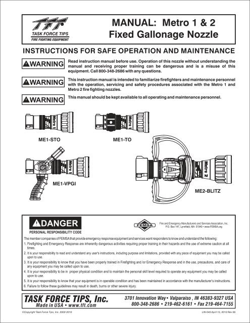
Metro 1Metro 1Metro 2Metro 1MANUAL: Metro 1 & 2Fixed Gallonage NozzleINSTRUCTIONS FOR SAFE OPERATION AND MAINTENANCEWARNINGWARNINGWARNINGRead instruction manual before use. Operation of this nozzle without understanding themanual and receiving proper training can be dangerous and is a misuse of thisequipment. Call 800-348-2686 with any questions.This instruction manual is intended to familiarize firefighters and maintenance personnelwith the operation, servicing and safety procedures associated with the Metro 1 andMetro 2 fire fighting nozzles.This manual should be kept available to all operating and maintenance personnel.ME1-STOME1-TOME1-VPGIME2-BLITZDANGERPERSONAL RESPONSIBILITY CODEFEMSAFire and Emergency Manufacturers and Services Association, Inc.P.O. Box 147, Lynnfield, MA 01940 • www.FEMSA.orgThe member companies of FEMSAthat provide emergency response equipment and services want responders to know and understand the following:1. Firefighting and Emergency Response are inherently dangerous activities requiring proper training in their hazards and the use of extreme caution atalltimes.2. It is your responsibility to read and understand any user's instructions, including purpose and limitations, provided with any piece of equipment you may be calledupon to use.3. It is your responsibility to know that you have been properly trained in Firefighting and /or Emergency Response and in the use, precautions, and care ofany equipment you may be called upon to use.4. It is your responsibility to be in proper physical condition and to maintain the personal skill level required to operate any equipment you may be calledupon to use.5. It is your responsibility to know that your equipment is in operable condition and has been maintained in accordance with the manufacturer’s instructions.6. Failure to follow these guidelines may result in death, burns or other severe injury.TASK FORCE TIPS, Inc.Made in USA • www.tft.com3701 Innovation Way• Valparaiso , IN 46383-9327 USA800-348-2686 • 219-462-6161 • Fax 219-464-7155©Copyright Task Force Tips, Inc. 2002-2010 LIN-040 April 15, 2010 Rev 06
1.02.03.04.0MEANING OF SAFETY SIGNAL WORDSGENERAL INFORMATION2.12.2VARIOUS MODELS AND TERMSNOZZLE COUPLINGS4. 3 PATTERN CONTROL4.4 FLUSH CONTROL4.5 USE WITH FOAM4.5.1 FOAM ASPIRATING ATTACHMENTSFLOW CHARACTERISTICS5.0 USE OF METRO NOZZLES3.1 FLOW SETTING3.2 WASHER SETTINGTABLE OF CONTENTS6.0 FIELD INSPECTION7.0 REPAIRNOZZLE CONTROLS8.0 ANSWERS TO YOUR QUESTIONS4.1 FLOW CONTROL9.0 METRO 1 DRAWINGS AND PARTS LIST4.1.14.1.24.1.3LEVER TYPE FLOW CONTROLTWIST SHUTOFFTIP ONLY NOZZLES10.011.012.0METRO 2 DRAWINGS AND PARTS LISTINSPECTION CHECKLISTWARRANTY4.2 BALL SHUTOFF1.0 MEANING OF SAFETY SIGNAL WORDSA safety related message is identified by a safety alert symbol and a signal word to indicate the level of risk involved with aparticular hazard. Per ANSI standard Z535.4-1998 the definitions of the three signal words are as follows:DANGERWARNINGCAUTIONDANGER indicates an imminently hazardous situation which, if not avoided, will result in death orserious injury.WARNING indicates a potentially hazardous situation which, if not avoided, could result in death orserious injury.CAUTION indicates a potentially hazardous situation which, if not avoided, may result in minor ormoderate injury.2.0 GENERAL INFORMATIONThe Task Force Tips Metro nozzles are designed to provide excellent performance under most fire fighting conditions. Their ruggedconstruction is compatible with the use of fresh water (see section 6.0 for saltwater use) as well as fire fighting foam solutions. Otherimportant operating features are: Interchangeable washer to allow for user defined flow and pressure; Quick-acting pattern controlfrom straight stream to wide fog; "Power fog teeth" for full-fill fog; Easily flushable while flowing to clear trapped debris; T F T ' s f i v e -year warranty and unsurpassed customer service.WARNINGWARNINGWARNINGWARNINGCAUTIONThis equipment is intended for use by trained personnel for firefighting. Their use for otherpurposes may involve hazards not addressed by this manual. Seek appropriate guidance andtraining to reduce risk of injury.Nozzle reaction will vary as supply conditions change: such as opening or closing other nozzles,hose line kinks, changes in pump settings, etc. Changes in spray pattern or flushing will also affectnozzle reaction. The nozzle operator must always be prepared in the event of those changes.Failure to restrain nozzle reaction can cause firefighter injury from loss of footing and/or streamprotection.If nozzle gets out of control or away from operator, retreat from nozzle immediately. Do not attemptto regain control of nozzle while flowing water. Injury from whipping can occur.Water is a conductor of electricity. Application of water solutions on high voltage equipment cancause injury or death by electrocution. The amount of current that may be carried back to the nozzlewill depend on the following factors: Voltage of the line or equipment; Distance from the nozzle tothe line or equipment; Size of the stream; Whether the stream is solid or broken; Purity of thewater 1Fire streams are capable of injury and damage. Do not direct water stream to cause injury ordamage to persons or property.21The Fire Fighter and Electrical Equipment, The University of Michigan Extension Service, Fourth Printing 1983. Page 47.©Copyright Task Force Tips, Inc. 2002-2010 LIN-040 April 15, 2010 Rev 06
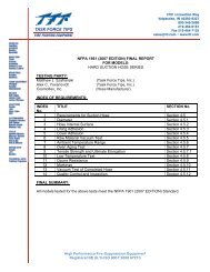
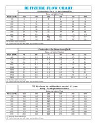
Metro 1Metro 1Metro 12.1 VARIOUS MODELS AND TERMSFixed Flow: A nozzle with a dischargeorifice that is a fixed opening size.Tip Only: a nozzle without an integralball shutoff valve. A Metro tip only nozzleis available in a variety of flow rangesand configurations. All models deliverthe rated flow when the rated pressure issupplied to the nozzle.SERIES RECOMMENDED FLOW SETTINGS NOZZLE TYPEHOSE SIZE (INCHES)METRO 1 1-1/2 Field Changeable Fixed Flow(small body)To Any of 10 SizesMETRO 2 1-1/2 to 2-1/2 Field Changeable Fixed Flow(large body)To Any of 8 SizesDETENTSCOUPLINGONFLOW CONTROLOFFSTREAMSHAPERNAME LABELBARRELLABELFLOWCONTROLWASHERVALVE POSITIONLABELVALVE RINGPISTOLGRIPNOZZLE WITH VALVEand INTEGRAL PISTOL GRIPTIP ONLY NOZZLETIP ONLY NOZZLEWITH TWIST SHUTOFFFIGURE 1COMMON MODEL AND TERMS2.2 NOZZLE COUPLINGNH (National Hose Threads per NFPA #1963) threads are standard on all nozzles. Other threads such as NPSH (National Pipe StraightHose threads per ANSI/ASME #B1.20.7) can be specified at time of order.CAUTIONNozzle must be properly connected. Mismatched or damaged threads may cause nozzle to leak oruncouple under pressure and could cause injury.CAUTIONDissimilar metals coupled together can cause galvanic corrosion that can result in the inability tounscrew the threads of complete loss of thread engagement over time. Per NFPA 1962 (1998edition), if dissimilar metals are left coupled together an anti-corrosive lubricant should be appliedto the threads. Also the coupling should be disconnected and inspected at least quarterly.3.0 FLOW CHARACTERISTICSThe opening size of the Metro nozzles may be field set to any one of the several different sizes. At each flow setting the nozzle is set to apredetermined fixed orifice. Relationship of flow and nozzle pressure at each setting is shown below.PRESSURE (PSI)METRO 1 FLOW CHARTFLOW (L/min)190 380 550 750 950 114015010.34 bar 1409.65 bar1308.96 bar1208.27 bar1107.58 bar1006.90 bar906.20 bar80 95 GPM @ 100 PSI (K=9.5) 5.52 bar125 GPM @ 100 PSI (K=12.5)704.83 bar 125 GPM @ 75 PSI (K=14.4)604.12 bar 150 GPM @ 100 PSI (K=15.0)50 150 GPM @ 75 PSI (K=17.3) 3.45 bar40 175 GPM @ 100 PSI (K=17.5) 2.76 bar30 200 GPM @ 100 PSI (K=20.0) 2.07 bar175 GPM @ 75 PSI (K=20.2)201.38 bar 150 GPM @ 50PSI (K=21.2)100.69 bar 200 GPM @ 75 PSI (K=23.1)00 50 100 150 200 250 300FLOW (GPM)©Copyright Task Force Tips, Inc. 2002-2010 LIN-040 April 15, 2010 Rev 063
3.0 FLOW CHARACTERISTICS (continued)REACTION FORCE (LBF)20018016014012010080604020METRO 1 FLOW VS REACTION FORCEFLOW (L/min)190 380 550 750 950 114090.7 kgf200 GPM @ 75 PSI (K=23.1)00 50 100 150 200 250 300FLOW (GPM)95 GPM @ 100 PSI (K=9.5)125 GPM @ 100 PSI (K=12.5)125 GPM @ 75 PSI (K=14.4)150 GPM @ 100 PSI (K=15.0)150 GPM @ 75 PSI (K=17.3)175 GPM @ 100 PSI (K=17.5)200 GPM @ 100 PSI (K=20.0)175 GPM @ 75 PSI (K=20.2)150 GPM @ 50 PSI (K=21.2)68.0 kgf45.4 kgf22.7 kgf150140130120110METRO 2 FLOW CHARTFLOW (L/min)190 380 550 750 950 1140 1325 1525 170010.34 bar9.65 bar8.96 bar8.27 bar7.58 barPRESSURE (PSI)100908070605040302010125 GPM @ 75 PSI (K=14.4)175 GPM @ 100 PSI (K=17.5)185 GPM @ 75 PSI (K=21.4)200 GPM @ 75 PSI (K=23.1)250 GPM @ 100 PSI (K=25.0)250 GPM @ 75 PSI (K=28.9)325 GPM @ 100 PSI (K=32.5)250 GPM @ 50 PSI (K=35.4)6.90 bar6.20 bar5.52 bar4.83 bar4.12 bar3.45 bar2.76 bar2.07 bar1.38 bar0.69 bar00 50 100 150 200 250 300 350 400 450FLOW (GPM)300METRO 2 FLOW VS. REACTION FORCEFLOW (L/min)190 380 550 750 950 1140 1325 1525 1700136.1 kgf250113.4 kgfREACTION FORCE (LBF)20015010050125 GPM @ 75 PSI (K=14.4)175 GPM @ 100 PSI (K=17.5)185 GPM @ 75 PSI (K=21.4)200 GPM @ 75 PSI (K=23.1)250 GPM @ 100 PSI (K=25.0)250 GPM @ 75 PSI (K=28.9)325 GPM @ 100 PSI (K=32.5)250 GPM @ 50 PSI (K=35.4)90.7 kgf68.0 kgf45.4 kgf22.7 kgf00 50 100 150 200 250 300 350 400 4504FLOW (GPM)©Copyright Task Force Tips, Inc. 2002-2010 LIN-040 April 15, 2010 Rev 06
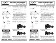
Metro 1Metro 13.1 FLOW SETTINGThe washers are marked with various flow settings. Change washer to the desired setting. The nozzle will flow the indicated amount whenthe pressure at the nozzle is at the indicated level.3.2 WASHER SETTINGTo change flow and pressure setting of the Metro, use thefollowing instructions:1) Set nozzle into FLUSH.2) Push baffle down to barrel cone.3) Remove screw and washer using a 5/32 hex key.4) Remove pre-set flow washer and slide desired flowwasher onto shaft, desired flow marking facing up.5) Thread screw with washer back into shaft until snug( Do not over tighten).NOTE: H410-** are not compatible with new Metro 2nozzlesSCREWVT25Y28BH500METRO 1&2WASHERVW687X281-50METRO 1&2FLOW WASHERHM410-** METRO 1HX410-** METRO 2SHAFTHM470 - METRO 1HX470 - METRO 2BAFFLEHM461 - METRO 1H461 - METRO 2DANGERWARNINGWARNINGWARNINGCAUTIONAn inadequate supply of nozzle pressure and/or flow will cause an ineffective stream and canresult in injury, death or loss of property. See flow charts in section 3.0 or call 800-348-2686 forassistance.Failure to secure screw and washer will result in the baffle becoming loose. This will produce poorstream, improper flows and possible discharge of the complete baffle, resulting in risk of injury.Failure to restrain nozzle reaction can cause firefighter injury from loss of footing and/or streamprotection. Nozzle reaction will vary as supply conditions change: such as opening or closingother nozzles, hose line kinks, changes in pump settings, etc. Changes in spray pattern or flushingwill also affect nozzle reaction. The nozzle operator must always be positioned to restrain thenozzle reaction in the event of those changes.Injury from whipping can occur. If nozzle gets out of control or away from operator, retreat fromnozzle immediately. Do not attempt to regain control of nozzle while flowing water.Fire streams are capable of injury and damage. Do not direct water stream to cause injury ordamage to persons or property.4.0 NOZZLE CONTROLS4.1 FLOW CONTROL4.1.1 LEVER TYPE FLOW CONTROLOn models that use a lever type valve handle, the nozzle is shut offwhen the handle is fully forward. The valve handle has six detent flowpositions. These detent positions allow the nozzle operator to regulatethe flow of the nozzle depending on the need or what can be safely andeffectively handled. TFT recommends the use of a pistol grip for easierhandling. For additional stress reduction, a hose rope or strap mayalso be used. This permits more effective use and ease ofadvancement, while minimizing strain and fatigue.ONFLOW CONTROLOFF4.1.2 TWIST SHUTTOFFOn models that use a twist flow control, the valve is opened or closedby rotating the valve ring. Rotating the ring clockwise (as seen from theoperating position behind the nozzle) closes the valve, whilecounterclockwise rotation opens it. Detents are provided at fourintermediate positions and the position of the valve is shown by theexposed valve position label.VALVE RINGVALVEPOSITIONLABELFLOW PATTERN LABEL©Copyright Task Force Tips, Inc. 2002-2010 LIN-040 April 15, 2010 Rev 065
Metro 2Metro 14.1.3 TIP ONLY NOZZLESTip only nozzles have NO shut off valve containedwithin the nozzle and MUST be used with aseparate ball valve attached to the nozzle.4.2 BALL VALVE SHUTOFFModels with a ball valve are shut off when the valvehandle is fully forward. Pulling back on the handle opensthe valve. Open valve slowly to avoid sudden changes innozzle reaction. Close valve slowly to prevent waterhammer. Note: In partially open positions a ball valve willcause turbulence and adversely affect stream quality.ONFLOW CONTROLOFFONFLOW CONTROLOFF4.3 PATTERN CONTROLTFT's Metro has full pattern control from straight stream to wide fog. Turning the STREAMSHAPER clockwise (as seen from the operating position behind the nozzle) moves theSHAPER to the straight stream position. Turning the SHAPER counterclockwise will result inan increasingly wider pattern.Since the stream trim point varies with the flow, the stream should be "trimmed" after changing the flow to obtain the straightest andfarthest reaching stream. To properly trim a stream, first open the pattern to a narrow fog. Then close the stream to parallel to givemaximum reach. NOTE: Turning the shaper further forward will cause stream crossover and reduce the effective reach of thenozzle.The nozzle reaction is greatest when the shaper is in the straight stream position. The nozzle operator must be prepared for a change inreaction as the pattern is changed.4.4 FLUSH CONTROLSmall debris may get caught inside the nozzle. This trapped material will cause poor stream quality, shortened reach and reduced flow.To remove this trapped debris the nozzle can be flushed as follows; while still flowing water, turn the SHAPER counterclockwise pastthe full fog position (increased resistance will be felt on the SHAPER as the nozzle goes into flush). This will open the nozzle allowingdebris to pass through. Rotate the SHAPER clockwise and out of flush to continue normal operation. During flush the nozzle reactionwill decrease as the pattern becomes wider and the pressure drops. The nozzle operator must be prepared for an increase of nozzlereaction when returning the nozzle from the flush position to retain control of the nozzle.WARNINGLarge amounts or pieces of debris may be unflushable and can reduce the flow of the nozzleresulting in an ineffective flow. In the event of a blockage, it may be necessary to retreat to asafe area, uncouple nozzle and remove debris.4.5 USE WITH FOAMThe Metro nozzles may be used with foam solutions. Refer to fire service training for the proper use of foam.WARNINGWARNINGFor Class B fires, lack of foam or interruption in the foam stream can cause a break in the foamblanket and greatly increase the risk of injury or death. Assure that: Application rate is sufficient(see NFPA 11 or foam manufacturer's recommendations); Enough concentrate is on hand tocomplete task (see NFPA for minimum duration time requirements); Foam logistics have beencarefully planned. Allow for such things as: Storage of foam in a location not exposed to the hazardit protects; Personnel, equipment and technique to deliver foam at a rapid enough rate; Removalof empty foam containers; Clear path to deliver foam, as hoses and other equipment and vehiclesare deployed.Improper use of foam can result in injury or damage to the environment. Follow foammanufacturer's instructions and fire service training to avoid: Using wrong type of foam on a fire,i.e. Class A foam on a Class B fire; Plunging foam into pools of burning liquid fuels; Causingenvironmental damage; Directing stream at personnel.6WARNINGThere is a wide variety of foam concentrates. Each user is responsible for verifying that any foamconcentrate chosen to be used with this unit has been tested to assure that the foam obtained issuitable for the purpose intended.©Copyright Task Force Tips, Inc. 2002-2010 LIN-040 April 15, 2010 Rev 06
4.5.1 FOAM ASPIRATING ATTACHMENTSTo increase the expansion ratio, Task Force Tips "MX Foamjet" (model FJ-MX-HM) multi expansion attachment or LX Foamjet (modelFJ-LX-HM) low expansion attachment may be used with the Metro 1 nozzle and (model FJ-HMX) multi expansion attachment or LXFoamjet (model FJ-H) low expansion attachment may be used with the Metro 2 nozzle. These foam tubes attach and detach quicklyfrom the nozzle. Note: As expansion ratio is increased, the reach of the nozzle will be decreased due to the greater amount of bubblesin the stream and their inability to penetrate the air. Generally the reach with foam is approximately 10% less than with water only. Actualresults will vary based on brand of foam, hardness of water, temperature, etc. See Foamjet instruction manual for specific information.5.0 USE OF METRO NOZZLESIT IS THE RESPONSIBILITY OF THE INDIVIDUAL FIRE DEPARTMENT OR AGENCY TO DETERMINE PHYSICAL CAPABILITIESAND SUITABILITY FOR AN INDIVIDUAL'S USE OF THIS EQUIPMENT.Many factors contribute to the extinguishment of a fire. Among the most important is delivering water at a flow rate sufficient to absorbheat faster than it is being generated. The flow rate depends largely on the pump discharge pressure and hose friction loss. It can becalculated using a hydraulic equation such as:PDP = NP+FL+DL+ELFor additional information on calculating specific hose layouts, consult anappropriate fire service training manual, such as IFSTA, or A Guide to AutomaticPDP = Pump discharge pressure in PSINozzles, or call TFT's "Hydraulics Hotline" at 800-348-2686.NP = Nozzle pressure in PSIFL = Hose friction loss in PSISee www.tft.com for flow rates at various pump pressures.DL = Device loss in PSIEL = Elevation loss in PSI6.0 FIELD INSPECTIONTFT's Metro is designed and manufactured to be damage resistant and require minimal maintenance. However, as the primary firefighting tools upon which your life depends, they should be treated accordingly.Use with saltwater is permissible provided nozzle is thoroughly cleaned with fresh water after each use. The service life of thenozzle may be shortened due to the effects of corrosion and is not covered under warranty.WARNINGNozzle must be inspected for proper operation and function according to inspection checklist on last pagebefore each use. Any nozzle that fails inspection is dangerous to use and must be repaired before using.Performance tests shall be conducted on the Metro nozzle after a repair, or anytime a problem is reported to verify operation inaccordance with TFT test procedures. Consult factory for the procedure that corresponds to the model and serial number of thenozzle. Any equipment which fails the related test criteria should be removed from service immediately. Troubleshooting guides areavailable with each test procedure or equipment can be returned to the factory for service and testing.Factory service is available with repair time seldom exceeding one day in our facility. Factory serviced nozzles are repaired byexperienced technicians to original specifications, fully tested and promptly returned. Any returns should include a note as to thenature of the problem, who to reach in case of questions and if a repair estimate is required.CAUTIONAny alterations to the nozzle and its markings could diminish safety and constitutes a misuse of thisproduct.All Task Force Tip nozzles are factory lubricated with high quality silicone grease. This lubricant has excellent washout resistance andlong term performance. If your department has unusually hard or sandy water, the moving parts may be affected. Foam agents andwater additives contain soaps and chemicals that may break down the factory lubrication.The moving parts of the nozzle should be checked on a regular basis for smooth and free operation, and signs of damage. IF THENOZZLE IS OPERATING CORRECTLY, THEN NO ADDITIONAL LUBRICATION IS NEEDED. Any nozzle that is not operatingcorrectly should be immediately removed from service and the problem corrected.7.0 REPAIRFactory service is available with repair time seldom exceeding one day in our facility. Factory-serviced nozzles are repaired byexperienced technicians to original specifications, fully wet tested, and promptly returned. Repair charges for non-warranty items areminimal. Any returns should include a note as to the nature of the problem and whom to reach in case of questions.Task Force Tips assumes no liability for damage to equipment or injury to personnel that is a result of user service.Repair kits and repair parts are stocked for immediate shipment. Contact the factory or visit the website at www.tft.com for parts lists,exploded views, test procedures and trouble shooting guides.8.0 ANSWERS TO YOUR QUESTIONSWe appreciate the opportunity of serving you and making your job easier. If you have any problems or questions, our toll-free"Hydraulics Hotline", 800-348-2686, is normally available to you 24 hours a day, 7 days a week.©Copyright Task Force Tips, Inc. 2002-2010 LIN-040 April 15, 2010 Rev 067
9.0 METRO 1 DRAWINGS &PART LISTBACK ENDPARTSFRONT END PARTS8©Copyright Task Force Tips, Inc. 2002-2010 LIN-040 April 15, 2010 Rev 06
METRO 1 - SERVICE PROCEDURE PARTS LISTDESCRIPTION QTY ORDER #1 1.5" COUPLING GASKET 1 V31302 1.5" ROCKER LUG COUPLING 1 HM697*5 3/16 SS BALLS 33 V21207 ¼-28 X 3/8 SOCKET SET SCREW 1 VT25-28SS3758 GASKET GRABBER 1 HM7309 O-RING-134 1 VO-13410 VALVE BODY 1VALVE DISK 2DRAG NUB 4SMALLEY RING 2HM600HM640HM650V427011 VALVE HANDLE 1 HM62012 DETENT SPRING 2 HM77013 DETENT BALL 2 VB243TO14 HANDLE SCREW 2 HM64515 CAM PIN 1 HM63016 SAFETY PIN 1 HM63517 VALVE HANDLE COVER 2 HM625-BLK18 8-32 x 3/8 BUTTON HEAD CAP SCREW 4 HM62619 10-32 x 3/16 SOCKET SET SCREW 2 VT10Y32SS18720 QUADX-4221 1 VOQ-422121 QUADX-4130 1 VOQ-413022 SLIDER 1 HM66023 VALVE PLUG 1 HM59026 S.T.O. TAIL PIECE 1 HM66227 O-RING-129 1 VO-12928 O-RING-138 1 VO-13829 S.T.O. SLIDER 1 HM66130 QUADX-4037 2 VOQ-403731 "OFF" LABEL 1 HD75532 "ON" LABEL 1 HD75033 S.T.O. BASE 1 HM65534 DETENT SPRING 2 VM420035 3/16" TORLON BALLS 2 V2120-TORLON36 S.T.O. SLEEVE 1 HM668DESCRIPTION QTY ORDER #37 DETENT SCREW 2 HD78538 CAM SCREW 2 HD78039 S.T.O. VALVE PLUG 1 HM59240 T.O. BASE 1 HM67041 T.O. VALVE PLUG 1 HM59146 O-RING-139 1 VO-13947 SHAPER GUIDE 1 HMD51048 NAME LABEL - Metro 1 1 HM745-ORG52 TORLON GUIDE BALLS 3 VB243TO53 FIN CAN/BARREL 1 HM54555 BARREL LABEL- Orange 1 HM740-ORG57 O-RING-030 1 VO-03058 WS-175-S02 SMALLEY RING 1 VR423059 FLUSH WAVE SPRING 1 HM78560 BARREL CONE 1 HM52061 1/8 NYLON BALL 64 V213562 O-RING-230 1 VO-23063 SHAPER WITH BUMPER 1 HM50064 ¼-28X¾SHCAPSCREW 1 VT25-28SH75065 LOCKING SLEEVE 1 HM57166 SHAFT 1 HM47067 O-RING 011 1 VO-01168 BAFFLE 1 HM46169 FLOW WASHER K=12.5 OR 9.5 1FLOW WASHER K=15.0 OR 14.4FLOW WASHER K=17.5 OR 17.3FLOW WASHER K-20.0 OR 20.2FLOW WASHER K=23.1 OR 21.2HM410-14HM410-15HM410-17HM410-21HM410-2370 FLAT WASHER 1 VW687X281-5071 ¼-28 X ½ BUTTON HEAD 1 VT25Y28BH50080 PISTOL GRIP 1 HM692-BLK81 SPACER 1 HM693-HM82 WASHER 1 VM490183 3/8-16 X 1 SOCKET HEAD CAP SCREW 1 VT37-16SH1.0* Specify Thread©Copyright Task Force Tips, Inc. 2002-2010 LIN-040 April 15, 2010 Rev 069
10.0 METRO 2 DRAWINGS &PART LISTBACK ENDPARTSCOUPLINGSVALVE PARTSFRONT END PARTSSPRAY ADJUSTMENT PARTS10©Copyright Task Force Tips, Inc. 2002-2010 LIN-040 April 15, 2010 Rev 06
METRO 2 - SERVICE PROCEDURE PARTS LISTDESCRIPTION QTY ORDER #1 CAP NUT 1 H4202 GASKET - 2.5" HOSE COUPLING 1 V31903 COUPLING 2.5" NH ROCKERLUG 1 P198N(P198I NPSH)4 3/16" BALL - 302 STAINLESS 37 V21205 1/4-28 X 3/16 SOCKET SET SCREW 1 VT25-28SS187¼-28 X 3/8 SOCKET SET SCREW(SWIVEL)VT25-28SS375(LOCK-OUT)6 O-RING-141 2-5/16 ID 3/32 C/S 1 VO-1417 ANTI GG RING 2 P1478 BARREL LABEL ORANGE 1 H740-ORG10 BARREL 1 HX44011 O-RING-033 1 VO-03316 BARREL CONE 1 HX52017 METRO2 NAME LABEL ORANGE 1 H745-ORG18 SHAPER GUIDE 1 HXD51019 O-RING-336 2-7/8 ID 3/16 C/S 1 VO-33620 3/16" BALL ACETAL 48 V211521 SHAPER WITH BUMPER 1 H50022 SHAFT 1 HX47023 O-RING-011 5/16 ID 1/16 C/S 2 VO-01124 BAFFLE 1 H46125 FLOW WASHER 1FLOW WASHER K=17.0 OR K=14.4 HX410-16FLOW WASHER K=23.1 OR K=21.3 HX410-22FLOW WASHER K=28.9 OR K=25.0 HX410-26FLOW WASHER K=35.4 OR K=32.5 HX410-3427 FLAT WASHER 1 VW687X281-5028 ¼-28 BUTTON HEAD SCREW 1 VT25Y28BH50029 SMALLEY RING 1 VR427030 WAVE SPRING 1 HX78531 2.5” ROCKERLUG COUPLING 1 P19732 O-RING 151 1 VO-15133 ¼-28 X ¼ SET SCREW 1 VT25-28SS25034 1/4-28 X 3/8 SOCKET SET SCREW 1 VT25-28SS375DESCRIPTION QTY ORDER #35 3/16 SS BALL 38 V212036 2.5” BLITZ BASE 1 H67538 ¼-20 ACORN NUT STAINLESS 8 VT25E20AC39 ¼-20 X 2” STUD STAINLESS 4 VT25-20ST2.040 ¼ WASHER 8 VW500X265-6341 BLITZ BRACKET 4 H67642 PLAYPIPE HANDLE 2 P22043 1.5” GASKET 1 V313044 1.5” ROCKERLUG COUPLING 1 H69445 SAFETY PIN 1 HX63546 VALVE HANDLE 1 HX62047 CAM PIN 1 HX63048 HANDLE SCREW 2 VT37E24BH75049 BLACK HANDLE COVER 2 HM625-BLK50 8-32 X 3/8 BUTTON HEAD 4 HM626-151 BALL .243” - TORLON 2 VB243TO52 DETENT SPRING 2 HM77053 DETENT VALVE BODY 1 P110BLUE VALVE LABEL 1 H75054 BALL VALVE SEAT 2 P10455 BALL VALVE 1 P10356 O-RING 227 1 VO-22757 PLAYPIPE ADAPTER 1 HX45058 GRIP SPACER 1 HM693-H59 PISTOL GRIP 1 HM692-BLK60 FLAT WASHER 1 VM490161 3/8-16 X 1 SOCKET HEAD CAP 1 VT37-16SH1.062 3/8-24 X 3/8 SOCKET SET SCREW 1 VT37-24SS37563 BALL .344” TORLON 3 VB344TO64 10-32 x 3/16 SOCKET SET SCREW 2 VT10Y32SS18765 3/16 X 9/16 HDP SPIROL 2 V200566 TRUNNION DRIVER 2 HX65067 TRUNNION LEFT 1 P120LTRUNNION RIGHT 1 P120R68 TRUNNION SHIM 2 P17069 O-RING 118 2 VO-118* Specify Thread©Copyright Task Force Tips, Inc. 2002-2010 LIN-040 April 15, 2010 Rev 0611
11.0 INSPECTION CHECKLISTNozzle must be inspected before each use for proper operation and function accordingto this checklist. Check that:1) There is no obvious damage such as missing, broken or loose parts, damaged labels, etc.2) Coupling is tight and leak free3) Valve handle moves freely though full range and shuts off flow4) Nozzle flow is adequate as indicated by pump pressure and nozzle reaction5) Shaper turns freely and adjusts pattern through full range6) Nozzle moves smoothly in and out of flush positionWARNINGAny nozzle failing any part of the inspection checklist is unsafe and must have the problemcorrected before use. Operating a nozzle that fails any of the above inspections is a misuse of thisequipment.12.0 WARRANTYTask Force Tips, Inc., 3701 Innovation Way, Valparaiso, Indiana 46383-9327 USA ("TFT") warrants to the original purchaser of its Metroseries nozzles ("equipment"), and to anyone to whom it is transferred, that the equipment shall be free from defects in material andworkmanship during the five (5) year period from the date of purchase.TFT's obligation under this warranty is specifically limited to replacing or repairing the equipment (or its parts) which are shown byTFT's examination to be in a defective condition attributable to TFT. To qualify for this limited warranty, the claimant must return theequipment to TFT, at 3701 Innovation Way, Valparaiso, Indiana 46383-9327 USA, within a reasonable time after discovery of thedefect. TFT will examine the equipment. If TFT determines that there is a defect attributable to it, TFT will correct the problemwithin a reasonable time. If the equipment is covered by this limited warranty, TFT will assume the expenses of repair.If any defect attributable to TFT under this limited warranty cannot be reasonably cured by repair or replacement, TFT may elect torefund the purchase price of the equipment, less reasonable depreciation, in complete discharge of its obligations under this limitedwarranty. If TFT makes this election, claimant shall return the equipment to TFT free and clear of any liens and encumbrances.This is a limited warranty. The original purchaser of the equipment, any person to whom it is transferred, and any person who isan intended or unintended beneficiary of the equipment, shall not be entitled to recover from TFT any consequential or incidentaldamages for injury to person and/or property resulting from any defective equipment manufactured or assembled by TFT. It isagreed and understood that the price stated for the equipment is in part consideration for limiting TFT's liability. Some states donot allow the exclusion or limitation of incidental or consequential damages, so the above may not apply to you.TFT shall have no obligation under this limited warranty if the equipment is, or has been, misused or neglected (including failure toprovide reasonable maintenance) or if there have been accidents to the equipment or if it has been repaired or altered by someoneelse.THIS IS A LIMITED EXPRESS WARRANTY ONLY. TFT EXPRESSLY DISCLAIMS WITH RESPECT TO THE EQUIPMENT ALLIMPLIED WARRANTIES OF MERCHANTABILITY AND ALL IMPLIED WARRANTIES OF FITNESS FOR A PARTICULARPURPOSE. THERE IS NO WARRANTY OF ANY NATURE MADE BY TFT BEYOND THAT STATED IN THIS DOCUMENT.This limited warranty gives you specific legal rights, and you may also have other rights which vary from state to state.TASK FORCE TIPS, Inc.Made in USA • www.tft.com3701 Innovation Way• Valparaiso , IN 46383-9327 USA800-348-2686 • 219-462-6161 • Fax 219-464-7155©Copyright Task Force Tips, Inc. 2002-2010 LIN-040 April 15, 2010 Rev 06