Scope Component Test Unit
Scope Component Test Unit
Scope Component Test Unit

You also want an ePaper? Increase the reach of your titles
YUMPU automatically turns print PDFs into web optimized ePapers that Google loves.
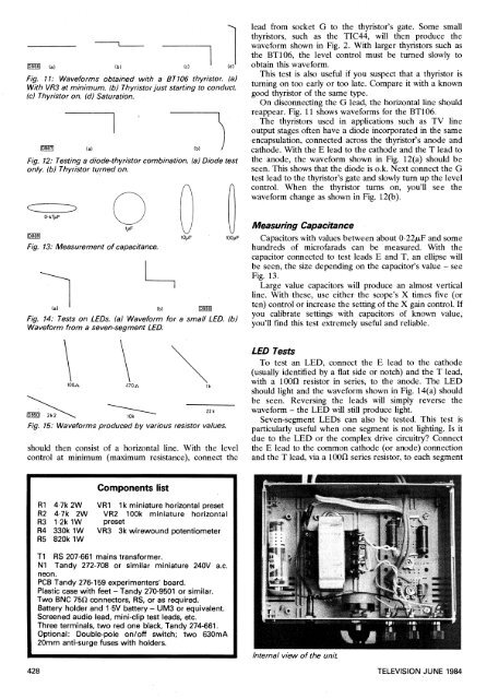
Fig. 11: Waveforms obtained with a BT106 thyristor. (a)With VR3 at minimum. (b) Thyristor just starting to conduct.(c) Thyristor on. (d) Saturation.Fig. 12: <strong>Test</strong>ing a diode-thyristor combination. (a) Diode testonly. (b) Thyristor turned on.lead from socket G to the thyristor's gate. Some smallthyristors, such as the TIC44, will then produce thewaveform shown in Fig. 2. With larger thyristors such asthe BT106, the level control must be turned slowly toobtain this waveform.This test is also useful if you suspect that a thyristor isturning on too early or too late. Compare it with a knowngood thyristor of the same type.On disconnecting the G lead, the horizontal line shouldreappear. Fig. 11 shows waveforms for the BT106.The thyristors used in applications such as TV lineoutput stages often have a diode incorporated in the sameencapsulation, connected across the thyristor's anode andcathode. With the E lead to the cathode and the T lead tothe anode, the waveform shown in Fig. 12(a) should beseen. This shows that the diode is o.k. Next connect the Gtest lead to the thyristor's gate and slowly turn up the levelcontrol. When the thyristor turns on, you'll see thewaveform change as shown in Fig. 12(b).Fig. 13: Measurement of capacitance.Fig. 14: <strong>Test</strong>s on LEDs. (a) Waveform for a small LED. (b)Waveform from a seven-segment LED.Measuring CapacitanceCapacitors with values between about 0.22euF and somehundreds of microfarads can be measured. With thecapacitor connected to test leads E and T, an ellipse willbe seen, the size depending on the capacitor's value — seeFig. 13.Large value capacitors will produce an almost verticalline. With these, use either the scope's X times five (orten) control or increase the setting of the X gain control. Ifyou calibrate settings with capacitors of known value,you'll find this test extremely useful and reliable.En 2 kFig. 15: Waveforms produced by various resistor values.10kshould then consist of a horizontal line. With the levelcontrol at minimum (maximum resistance), connect the22 kLED <strong>Test</strong>sTo test an LED, connect the E lead to the cathode(usually identified by a flat side or notch) and the T lead,with a 100f/ resistor in series, to the anode. The LEDshould light and the waveform shown in Fig. 14(a) shouldbe seen. Reversing the leads will simply reverse thewaveform — the LED will still produce light.Seven-segment LEDs can also be tested. This test isparticularly useful when one segment is not lighting. Is itdue to the LED or the complex drive circuitry? Connectthe E lead to the common cathode (or anode) connectionand the T lead, via a 100f/ series resistor, to each segment<strong>Component</strong>s listR1 4.7k 2W VR1 1k miniature horizontal presetR2 4.7k 2W VR2 100k miniature horizontalR3 1.2k 1W presetR4 330k 1W VR3 3k wirewound potentiometerR5 820k 1WTi RS 207-661 mains transformer.Ni Tandy 272-708 or similar miniature 240V a.c.neon.PCB Tandy 276-159 experimenters' board.Plastic case with feet — Tandy 270-9501 or similar.Two BNC 750 connectors, RS, or as required.Battery holder and 1.5V battery — UM3 or equivalent.Screened audio lead, mini-clip test leads, etc.Three terminals, two red one black, Tandy 274-661.Optional: Double-pole on/off switch; two 630mA20mm anti-surge fuses with holders.Internal view of the unit.428 TELEVISION JUNE 1984