Rear Suspension - - Freel2.com
Rear Suspension - - Freel2.com
Rear Suspension - - Freel2.com
- No tags were found...

Create successful ePaper yourself
Turn your PDF publications into a flip-book with our unique Google optimized e-Paper software.
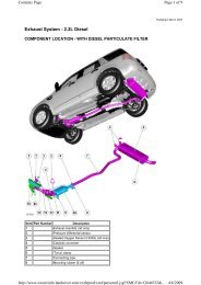
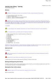
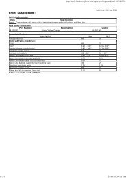
http://topix.landrover.jlrext.com/topix/service/procedure/146634/OD...4 of 6 23/02/2012 7:36 AM11Locknut12Bush - outer13Washer14Bolt15Front transverse link16Bush - inner17BoltLateral wheel location is provided by 2 transverse links which are located between the subframe and the wheel knuckle. Thelinks are long to give excellent camber control. Each link is fitted with dynamic bushes to control the rear camber in aprogressive manner as cornering loads increase which gives a limited amount of passive rear wheel steering. The 2 transverselinks are different in their design. The front link is a steel pressing. The rear link is fabricated from squeezed and croppedtube. The links are designed to withstand vehicle jacking loads.The front transverse link is fitted with bushes which compress under cornering forces to provide a controlled amount of rearwheel toe-in, in addition to the camber control. The front link has a deform point in a central position along its length. Thisallows the link to be deformed in the event of a severe lateral rear wheel impact, for example striking a kerb. In the event ofa severe lateral impact, the link will permanently deform, absorbing the impact and protecting the subframe from damage.The amount of deformation creates excessive toe-in which is immediately noticeable to the driver.The rear transverse link is mounted to the subframe using an eccentric bolt and washer which allows for adjustment of thewheel toe angle.Both transverse links are attached to the subframe with bolts and locknuts. The outer ends of each link locate in mountingholes integral with the wheel knuckle and are secured with bolts and locknuts.LONGITUDINAL LINKItem1234567DescriptionBody mounting bracketBoltLocknutLongitudinal linkBoltsLocknutBush
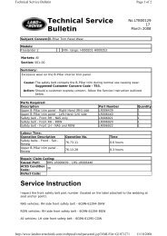
http://topix.landrover.jlrext.com/topix/service/procedure/146634/OD...5 of 6 23/02/2012 7:36 AM8BoltThe longitudinal links are fabricated from squeezed and cropped tube and are located between the wheel knuckle and thevehicle body. The links control the rear suspension in reaction to braking and traction forces.The rear mounting is forked and locates on either side of a bush pressed into the wheel knuckle. The link is secured with abolt and locknut which passes through the bush.The front mounting of the link locates in a bracket which is bolted to the underside of the vehicle sill. The link is fitted with abush which locates in the bracket and is secured with a bolt and locknut.WHEEL KNUCKLE AND HUBItemDescription1Clamp bolt2Wheel knuckle3Anti-lock Brake system (ABS) wheel speed sensor4Brake caliper attachment5Bearing6Circlip7Hub8Studs9Disc shield attachment10Bush - Longitudinal link11Front transverse link attachmentThe cast steel wheel knuckle provides the attachment for the transverse links, longitudinal link, spring and damper assemblyand the wheel hub and bearing assembly.An extended lower boss on the knuckle is fitted with a pressed bush and provides for the attachment of the longitudinal link.The link is secured to the knuckle with a bolt and locknut which passes through both the link and the bush.Two further bosses on the inside face of the wheel knuckle allow for the attachment of the front and rear transverse linkswhich are each secured with a bolt and locknut.The upper section of the wheel knuckle has a location hole for the damper body. The damper body slides into the hole andlocates against an abutment on the damper body. The rear face of the hole is split and allows the damper body to be securedin the wheel knuckle with a clamp bolt.
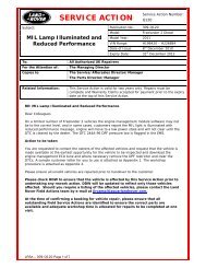
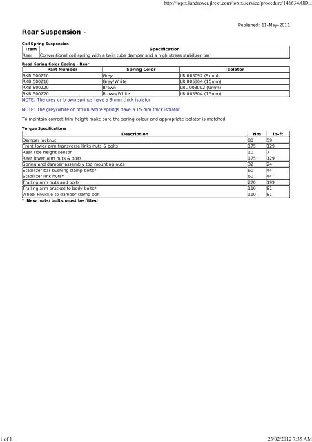
http://topix.landrover.jlrext.com/topix/service/procedure/146634/OD...6 of 6 23/02/2012 7:36 AMMounting locations are provided for the brake caliper and the brake disc shield. A hole in the top face of the wheel knuckleprovides the location for the ABS wheel speed sensor which is secured with a bolt.The wheel hub assembly includes the wheel bearing and ABS sensor pulse ring. The hub assembly is a non-serviceablecomponent and requires replacement as a complete assembly.STABILIZER BARItemDescription1Locknut2Ball joint3Link4Ball joint5Stabilizer bar6Bush7Bolt8Collar9ClampThe stabilizer bar is attached to the rear of the subframe with bushes and mounting brackets. The pressed steel bracketslocate over the bushes and are attached to the cross member with bolts screwed into threaded locations in the subframe. Thestabilizer bar has 'anti-shuffle' collars pressed in position on the inside edges of the bushes. The collars prevent sidewaysmovement of the stabilizer bar.The stabilizer bar is manufactured from 22 mm diameter, manganese steel bar. Each end of the stabilizer bar curves forwardsto attach to a ball joint on a stabilizer link. Each stabilizer link is secured to a bracket on the damper body with a locknut. Thelinks, which are not handed, allow the stabilizer bar to move with the wheel travel providing maximum effectiveness. Thestabilizer bar bushes are of the compression type which grip the bar under compression by the clamps.The stabilizer bar bushes are the compression type which grip the bar under compression by the mounting brackets. Whenfitting replacement bushes to the bar it is important to ensure the bushes are correctly orientated to the bar. Failure tocorrectly align the bushes will result in excessive pre-load (wind-up) in the bushes when the suspension is at its nominal rideheight.
http://topix.landrover.jlrext.com/topix/service/procedure/146634/OD...1 of 6 23/02/2012 7:36 AM<strong>Rear</strong> <strong>Suspension</strong> - <strong>Rear</strong> Wheel BearingRemoval and InstallationPublished: 11-May-2011Special Tool(s)204-528/2Remover/Installer, Bushing205-725Remover/Installer, Wheel Hub205-726Remover/Installer, Wheel Hub Bearing205-728Remover/Installer, Wheel Hub205-802/5Remover, Wheel Hub/BearingRemoval1.WARNING: Make sure to support the vehicle with axle stands.Raise and support the vehicle.2.Remove the wheel and tire.Refer to: Wheel and Tire (204-04 Wheels and Tires, Removal andInstallation).3.Remove the wheel knuckle.
http://topix.landrover.jlrext.com/topix/service/procedure/146634/OD...2 of 6 23/02/2012 7:36 AMRefer to: Wheel Knuckle (204-02 <strong>Rear</strong> <strong>Suspension</strong>, Removal andInstallation).4.5.6.7.
http://topix.landrover.jlrext.com/topix/service/procedure/146634/OD...3 of 6 23/02/2012 7:36 AM8.NOTE: Bearing damage is unavoidable during thisoperation.Position the wheel knuckle assembly in a pressand support on special tool.Special Tool(s): 205-802/5Press the drive flange out of the wheel knuckleassembly using special tool.Special Tool(s): 205-7259.NOTE: The inner bearing track will remain on the driveflange.10.Clamp both halves of a suitable bearing separatoraround the inner bearing track and position thedrive flange in a press.Using the special tool, press the drive flange fromthe inner bearing track.Special Tool(s): 205-725
http://topix.landrover.jlrext.com/topix/service/procedure/146634/OD...4 of 6 23/02/2012 7:36 AM11. Remove the circlip from the wheel knuckle assembly.12.Position the wheel knuckle assembly in a pressand support on special tools.Special Tool(s): 205-728Press the wheel bearing out of the wheel knuckleassembly using special tool.Special Tool(s): 205-726Installation1.CAUTION: One side of the bearing is magnetic. Themagnetic side is identifiable by the application of a mattblack finish. The magnetic side must face towards theinboard side of the vehicle. Before fitting the bearing,make sure the magnetic face is clean. The bearing mustbe handled with extreme care.Position the wheel knuckle assembly in a pressand support on special tool.Special Tool(s): 204-528/2Press the new wheel bearing into the wheelknuckle assembly using special tool.Special Tool(s): 205-7262.Install the circlip to the wheel knuckle assembly.
http://topix.landrover.jlrext.com/topix/service/procedure/146634/OD...5 of 6 23/02/2012 7:36 AM3.Position the wheel knuckle assembly in a pressand support on special tool.Special Tool(s): 205-726Press the drive flange into the wheel knuckleassembly using special tool.Special Tool(s): 205-7254.WARNING: Do not use compressed air to clean brakecomponents. Dust from friction materials can be harmful if inhaled.Clean the backing plate and apply grease to the brake shoe contacts.5.Clean the adjuster and set it to its minimum extension.6.Install the secondary brake shoe.Install the hold-down spring and retaining pin.7.WARNING: Make sure the return spring and the adjuster springare correctly installed to the primary shoe.CAUTION: Make sure the brake shoe spring is not overstretched.Install the spreader plate and the spring.Install the primary brake shoe.Install the return spring.Install the hold-down spring and retaining pin.8.CAUTION: Make sure the brake shoe spring is not overstretched.Install the brake shoe adjuster.9.Install the wheel knuckle.Refer to: Wheel Knuckle (204-02 <strong>Rear</strong> <strong>Suspension</strong>, Removal andInstallation).10.Adjust the parking brake.Refer to: Parking Brake Cable Adjustment (206-05 Parking Brake andActuation, General Procedures).
http://topix.landrover.jlrext.com/topix/service/procedure/146634/OD...6 of 6 23/02/2012 7:36 AM11. Install the wheel and tire.Refer to: Wheel and Tire (204-04 Wheels and Tires, Removal andInstallation).
http://topix.landrover.jlrext.com/topix/service/procedure/146634/OD...1 of 3 23/02/2012 7:36 AM<strong>Rear</strong> <strong>Suspension</strong> - Front Lower ArmRemoval and InstallationPublished: 11-May-2011Removal1.WARNING: Make sure to support the vehicle with axle stands.Raise and support the vehicle.2.Remove the wheel and tire.Refer to: Wheel and Tire (204-04 Wheels and Tires, Removal andInstallation).3.Discard the bolt.4.5.Partially release the bolt for access. Cut off the bolt head andwithdraw in the opposite direction.On installation, reverse the orientation of the new bolt.Make sure the captive nut and protective shield from theservice kit is installed.
http://topix.landrover.jlrext.com/topix/service/procedure/146634/OD...2 of 3 23/02/2012 7:36 AM6.Installation1.Install the front lower arm.2.CAUTION: Nuts and bolts must be tightened with the weight ofthe vehicle on the suspension.Install the nuts, bolts and washers, do not tighten at this stage.3.CAUTION: Nuts and bolts must be tightened with the weight ofthe vehicle on the suspension.Support weight of vehicle on a jack at the rear hub.4.Tighten the nuts and bolts.Torque: 175 Nm5.WARNING: Make sure that a new bolt is installed.Install the parking brake cable retaining bolt.Torque: 10 Nm6.Install the rear wheel.Refer to: Wheel and Tire (204-04 Wheels and Tires, Removal andInstallation).
http://topix.landrover.jlrext.com/topix/service/procedure/146634/OD...3 of 3 23/02/2012 7:36 AM7. Check and if necessary, adjust the rear wheel alignment
http://topix.landrover.jlrext.com/topix/service/procedure/146634/OD...1 of 2 23/02/2012 7:36 AM<strong>Rear</strong> <strong>Suspension</strong> - Trailing ArmRemoval and InstallationPublished: 11-May-2011Removal1.WARNING: Make sure to support the vehicle with axle stands.Raise and support the vehicle.2.Remove the wheel and tire.Refer to: Wheel and Tire (204-04 Wheels and Tires, Removal andInstallation).3.4.Installation1.Install the trailing link.2.Fit nuts, bolts and washers securing the trailing link to the body andhub, but do not tighten at this stage.3.CAUTION: Nuts and bolts must be tightened with the weight ofthe vehicle on the suspension.Support weight of vehicle on a jack at the rear hub.4.Tighten the nuts and bolts.
http://topix.landrover.jlrext.com/topix/service/procedure/146634/OD...2 of 2 23/02/2012 7:36 AMTorque: 270 Nm5.Install the wheel and tire.Refer to: Wheel and Tire (204-04 Wheels and Tires, Removal andInstallation).6.Check and if necessary, adjust the rear wheel alignment
http://topix.landrover.jlrext.com/topix/service/procedure/146634/OD...1 of 1 23/02/2012 7:36 AM<strong>Rear</strong> <strong>Suspension</strong> - <strong>Rear</strong> Stabilizer BarRemoval and InstallationPublished: 11-May-2011RemovalNOTE: Removal steps in this procedure may contain installation details.1.WARNING: Make sure to support the vehicle with axle stands.Raise and support the vehicle.2.CAUTIONS:Make sure that the ball joint ball does not rotate.Discard the nuts.Disconnect both rear stabilizer bar links from thestabilizer bar.Torque: 60 Nm3.Remove the stabilizer bar bushings.Refer to: <strong>Rear</strong> Stabilizer Bar Bushing (204-02 <strong>Rear</strong> <strong>Suspension</strong>,Removal and Installation).4.CAUTION: Note the fitted position of the component prior toremoval.Remove the stabilizer bar.Installation1.To install, reverse the removal procedure.
http://topix.landrover.jlrext.com/topix/service/procedure/146634/OD...1 of 2 23/02/2012 7:37 AM<strong>Rear</strong> <strong>Suspension</strong> - <strong>Rear</strong> Stabilizer Bar BushingRemoval and InstallationPublished: 11-May-2011Removal1.WARNING: Make sure to support the vehicle with axle stands.Raise and support the vehicle.2.CAUTION: Discard the bolts.NOTE: Muffler has been removed for clarity.3.Installation1.CAUTION: Make sure that the component is clean, free of foreignmaterial and lubricant.Install the stabilizer bar bushings.2.CAUTION: Make sure that the component is clean, free of foreignmaterial and lubricant.Install the stabilizer bar clamps.3.CAUTION: Make sure that new bolts are installed.Install the bolts, but do not tighten fully at this stage.4.CAUTION: Nuts and bolts must be tightened with the weight ofthe vehicle on the suspension.
http://topix.landrover.jlrext.com/topix/service/procedure/146634/OD...2 of 2 23/02/2012 7:37 AMTighten the stabilizer bar clamp bolts.Torque: 60 Nm
http://topix.landrover.jlrext.com/topix/service/procedure/146634/OD...1 of 1 23/02/2012 7:37 AM<strong>Rear</strong> <strong>Suspension</strong> - <strong>Rear</strong> Stabilizer Bar LinkRemoval and InstallationPublished: 11-May-2011RemovalNOTE: Removal steps in this procedure may contain installation details.1.WARNING: Make sure to support the vehicle with axle stands.Raise and support the vehicle.2.Remove the wheel and tire.Refer to: Wheel and Tire (204-04 Wheels and Tires, Removal andInstallation).3.CAUTIONS:Make sure that the ball joint ball does not rotate.Discard the nuts.Torque: 60 NmInstallation1.To install, reverse the removal procedure.
http://topix.landrover.jlrext.com/topix/service/procedure/146634/OD...1 of 13 23/02/2012 7:37 AM<strong>Rear</strong> <strong>Suspension</strong> - Wheel KnuckleRemoval and InstallationPublished: 18-May-2011Special Tool(s)204-159Lever, Wheel Knuckle204-528/2Remover/Installer, Bushing204-620-01Installer, Wheel Knuckle Bushing204-620-02Remover/Installer, Wheel Knuckle Bushing204-620-03Remover, Wheel Knuckle Bushing205-725Remover/Installer, Wheel Hub205-726Remover/Installer, Wheel Hub Bearing
http://topix.landrover.jlrext.com/topix/service/procedure/146634/OD...2 of 13 23/02/2012 7:37 AM205-728Remover/Installer, Wheel Hub205-802/5Remover, Wheel Hub/Bearing205-857Remover, HalfshaftLR-121Hydraulic Cylinder 10tRemoval1.WARNING: Make sure to support the vehicle with axle stands.Raise and support the vehicle.2.Remove the wheel and tire.Refer to: Wheel and Tire (204-04 Wheels and Tires, Removal andInstallation).3.CAUTION: Do not use a hammer to detach thehalfshaft from the hub assembly, failure to follow thisinstruction may result in damage to the halfshaft.Remove and discard the rear halfshaft nut.
http://topix.landrover.jlrext.com/topix/service/procedure/146634/OD...3 of 13 23/02/2012 7:37 AM4.CAUTION: Discard the nut.NOTE: RH illustration shown, LH is similar.5.Release the wheel speed sensor from the wheel knuckle.6.CAUTION: Make sure that no load is placed on thebrake hose.Tie the brake caliper and brake caliper anchorplate assembly aside.
http://topix.landrover.jlrext.com/topix/service/procedure/146634/OD...4 of 13 23/02/2012 7:37 AM7.Release the park brake shoe adjustment.8.Remove the brake disc.9.Release the parking brake cable from the wheelknuckle.Collect the clip.
http://topix.landrover.jlrext.com/topix/service/procedure/146634/OD...5 of 13 23/02/2012 7:37 AM10.11.CAUTIONS:Do not allow halfshafts to hang unsupported at oneend or joint damage will occur.Do not store or install halfshafts with joints atmaximum articulation or damage may occur to the joint.Angularly Adjusted Roller (AAR) joints, used at theinboard end of some halfshafts have no internal retainingmechanism and can separate.Release the rear halfshaft.Special Tool(s): 205-857Tie the rear halfshaft aside.12.Remove and discard the wheel knuckle clamping bolt.
http://topix.landrover.jlrext.com/topix/service/procedure/146634/OD...6 of 13 23/02/2012 7:37 AM13. With assistance, remove the wheel knuckle assembly.Special Tool(s): 204-15914.NOTE: Do not disassemble further if the component isremoved for access only.15.
http://topix.landrover.jlrext.com/topix/service/procedure/146634/OD...7 of 13 23/02/2012 7:37 AM16.17.18.NOTE: Bearing damage is unavoidable during thisoperation.Position the wheel knuckle assembly in a pressand support on special tool.Special Tool(s): 205-802/5Press the drive flange out of the wheel knuckleassembly using special tool.Special Tool(s): 205-725
http://topix.landrover.jlrext.com/topix/service/procedure/146634/OD...8 of 13 23/02/2012 7:37 AM19.NOTE: The inner bearing track will remain on the driveflange.20.Clamp both halves of a suitable bearing separatoraround the inner bearing track and position thedrive flange in a press.Using the special tool, press the drive flange fromthe inner bearing track.Special Tool(s): 205-72521.Remove the circlip from the wheel knuckle assembly.
http://topix.landrover.jlrext.com/topix/service/procedure/146634/OD...9 of 13 23/02/2012 7:37 AM22.Position the wheel knuckle assembly in a pressand support on special tools.Special Tool(s): 205-728Press the wheel bearing out of the wheel knuckleassembly using special tool.Special Tool(s): 205-72623.Remove the brake backing plate.24.CAUTION: Mark the components to aid installation.Remove the wheel knuckle bushing.Special Tool(s): LR-121, 204-620-02, 204-620-03Installation
http://topix.landrover.jlrext.com/topix/service/procedure/146634/OD...11 of 13 23/02/2012 7:37 AM6.Position the wheel knuckle assembly in a pressand support on special tool.Special Tool(s): 205-726Press the drive flange into the wheel knuckleassembly using special tool.Special Tool(s): 205-7257.WARNING: Do not use compressed air to clean brakecomponents. Dust from friction materials can be harmful if inhaled.Clean the backing plate and apply grease to the brake shoe contacts.8.Clean the adjuster and set it to its minimum extension.9.Install the secondary brake shoe.Install the hold-down spring and retaining pin.10.WARNING: Make sure the return spring and the adjuster springare correctly installed to the primary shoe.CAUTION: Make sure the brake shoe spring is not overstretched.Install the spreader plate and the spring.Install the primary brake shoe.Install the return spring.Install the hold-down spring and retaining pin.11.CAUTION: Make sure the brake shoe spring is not overstretched.Install the brake shoe adjuster.12.With assistance, install the wheel knuckle assembly.Special Tool(s): 204-15913.Install a new wheel knuckle clamping bolt.Torque: 110 Nm14.Install the rear halfshaft to the drive flange.
http://topix.landrover.jlrext.com/topix/service/procedure/146634/OD...12 of 13 23/02/2012 7:37 AM15.CAUTION: Only tighten the nut finger tight at this stage.Install a new rear halfshaft nut, do not fully tighten at this stage.16.CAUTION: Only tighten the nuts and bolts finger tight at thisstage.Connect both lower arms to the hub assembly, do not fully tighten atthis stage.17.CAUTION: Only tighten the nut and bolt finger-tight at thisstage.Connect the trailing arm to the hub assembly, do not fully tighten atthis stage.18.CAUTION: Make sure that the clip is correctly located.Connect the parking brake cable.Secure the parking brake cable.19.CAUTION: Make sure that the mating faces are clean and free offoreign material.Install the brake disc.Torque: 35 Nm20.CAUTIONS:Make sure that the mating faces are clean and free of foreignmaterial.Make sure that the brake hose is not twisted and is correctlylocated.Secure the brake caliper and anchor plate to the wheel knuckle.Torque: 110 Nm21.Install the rear wheel speed sensor to the wheel knuckle.Torque: 5 Nm22.Install the brake line and wheel speed sensor brackets.Torque: 10 Nm23.WARNING: Make sure that a new nut is installed.Secure the stabilizer bar link.Torque: 60 Nm24. 25. Support CAUTIONS: the weight of the vehicle using a jack under the rear hub.
http://topix.landrover.jlrext.com/topix/service/procedure/146634/OD...13 of 13 23/02/2012 7:37 AMNuts and bolts must be tightened with the weight of the vehicleon the suspension.Do not use air tools to install the nut. Failure to follow thisinstruction may result in damage to the component.Tighten both lower arm nuts and bolts.Torque: 175 NmTighten the trailing arm nut and bolt.Torque: 270 NmTighten the rear halfshaft nut.Torque:Stage 1: 330 NmStage 2: 30°Stake the hub nut.26.Adjust the parking brake.Refer to: Parking Brake Cable Adjustment (206-05 Parking Brake andActuation, General Procedures).27.Install the wheel and tire.Refer to: Wheel and Tire (204-04 Wheels and Tires, Removal andInstallation).
http://topix.landrover.jlrext.com/topix/service/procedure/146634/OD...1 of 2 23/02/2012 7:37 AM<strong>Rear</strong> <strong>Suspension</strong> - <strong>Rear</strong> Shock AbsorberRemoval and InstallationPublished: 11-May-2011RemovalNOTE: Removal steps in this procedure may contain installation details.1.WARNING: Make sure to support the vehicle with axle stands.Raise and support the vehicle.2.Remove the shock absorber and spring assembly.Refer to: Shock Absorber and Spring Assembly (204-02 <strong>Rear</strong><strong>Suspension</strong>, Removal and Installation).3.WARNINGS:Always follow the spring compressormanufacturer's instructions.Take extra care when handling the compressedspring.NOTE: Make sure that this component is installed to thenoted removal position.Remove the spring.4.Remove the shock absorber damper rod components.Installation1.Install the shock absorber shaft dust shield, spring aid and gaiter.2.WARNING: Take extra care when handling the compressedspring.
http://topix.landrover.jlrext.com/topix/service/procedure/146634/OD...2 of 2 23/02/2012 7:37 AMCAUTIONS:Make sure that these components are installed to the notedremoval position.Make sure that the mating faces are clean and free of foreignmaterial.Install the spring.3.Install the spring inclination spacer and top mount, install the nut butdo not fully tighten at this stage.4.Carefully release the spring tension.5.Tighten the nut.Torque: 80 Nm6.Install the cap.7.Install the shock absorber and spring assembly.Refer to: Shock Absorber and Spring Assembly (204-02 <strong>Rear</strong><strong>Suspension</strong>, Removal and Installation).
http://topix.landrover.jlrext.com/topix/service/procedure/146634/OD...1 of 4 23/02/2012 7:37 AM<strong>Rear</strong> <strong>Suspension</strong> - Shock Absorber and Spring AssemblyRemoval and InstallationPublished: 11-May-2011Removal1.Remove the rear quarter trim panel.Refer to: <strong>Rear</strong> Quarter Trim Panel (501-05 Interior Trim andOrnamentation, Removal and Installation).2.WARNING: Make sure to support the vehicle with axle stands.Raise and support the vehicle.3.Remove the wheel and tire.Refer to: Wheel and Tire (204-04 Wheels and Tires, Removal andInstallation).4.CAUTION: Make sure that no load is placed on thebrake hose.5.CAUTION: Discard the nut.
http://topix.landrover.jlrext.com/topix/service/procedure/146634/OD...2 of 4 23/02/2012 7:37 AM6.Remove and discard the bolt from the rear wheelknuckle.7.8.9.CAUTION: Make sure that no components catch.
http://topix.landrover.jlrext.com/topix/service/procedure/146634/OD...3 of 4 23/02/2012 7:37 AM10.Installation1.CAUTION: Make sure that new bolts are installed.Install the shock absorber to the hub assembly.Torque: 110 Nm2.Install the shock absorber and spring assembly.Torque: 32 Nm3.CAUTION: Nuts and bolts must be tightened with the weight ofthe vehicle on the suspension.Install the lower suspension arms.4.Install the brake line and wheel speed sensor brackets.Torque: 10 Nm5.WARNING: Make sure that a new nut is installed.Secure the stabilizer bar link.Torque: 60 Nm6.CAUTIONS:Make sure that the mating faces are clean and free of foreignmaterial.Make sure that the brake hose is not twisted and is correctlylocated.Secure the brake caliper and anchor plate to the wheel knuckle.Torque: 110 Nm7.CAUTION: Nuts and bolts must be tightened with the weight ofthe vehicle on the suspension.
http://topix.landrover.jlrext.com/topix/service/procedure/146634/OD...4 of 4 23/02/2012 7:37 AMSupport weight of vehicle on a jack at the rear hub.8.Tighten the trailing arm nut and bolt.Torque: 270 Nm9.Tighten the front and rear lower arm nuts and bolts.Torque: 175 Nm10.Install the wheel and tire.Refer to: Wheel and Tire (204-04 Wheels and Tires, Removal andInstallation).11.Install the rear quarter trim panel.Refer to: <strong>Rear</strong> Quarter Trim Panel (501-05 Interior Trim andOrnamentation, Removal and Installation).
http://topix.landrover.jlrext.com/topix/service/procedure/146634/OD...1 of 2 23/02/2012 7:37 AM<strong>Rear</strong> <strong>Suspension</strong> - Wheel Knuckle <strong>Rear</strong> BushingRemoval and InstallationPublished: 11-May-2011Special Tool(s)204-620-01Installer, Wheel Knuckle Bushing204-620-02Remover/Installer, Wheel Knuckle Bushing204-620-03Remover, Wheel Knuckle BushingLR-121Hydraulic Cylinder 10tRemoval1.WARNING: Make sure to support the vehicle with axle stands.Raise and support the vehicle.2.Remove the wheel and tire.Refer to: Wheel and Tire (204-04 Wheels and Tires, Removal andInstallation).3.Remove the trailing arm.Refer to: Trailing Arm (204-02 <strong>Rear</strong> <strong>Suspension</strong>, Removal andInstallation).
http://topix.landrover.jlrext.com/topix/service/procedure/146634/OD...2 of 2 23/02/2012 7:37 AM4.CAUTION: Mark the components to aid installation.Remove the bushing.Special Tool(s): LR-121, 204-620-02, 204-620-03Installation1.CAUTION: Make sure that the installation marksare aligned.2.CAUTION: Make sure the correct special tool isused to install the bushings to the correct depth.Install the bushing.Special Tool(s): LR-121, 204-620-01, 204-620-023.Install the trailing arm.Refer to: Trailing Arm (204-02 <strong>Rear</strong> <strong>Suspension</strong>, Removal andInstallation).4.Install the wheel and tire.Refer to: Wheel and Tire (204-04 Wheels and Tires, Removal andInstallation).