View Specification Sheet - Electric Motor Warehouse
View Specification Sheet - Electric Motor Warehouse
View Specification Sheet - Electric Motor Warehouse

You also want an ePaper? Increase the reach of your titles
YUMPU automatically turns print PDFs into web optimized ePapers that Google loves.
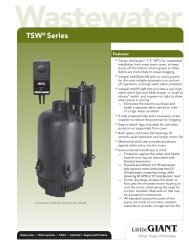
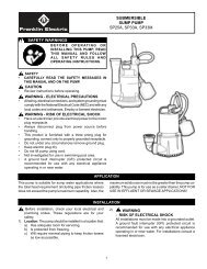
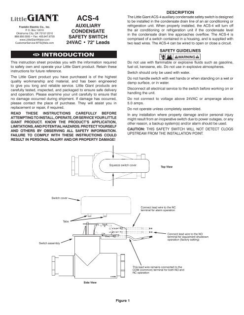
Franklin <strong>Electric</strong> Co., Inc.P. O. Box 12010Oklahoma City, OK 73157-2010888.956.0000 • Fax: 405.947.8720www.LittleGiantWater.comCustomerService-WTS@fele.comACS-4AUXILIARYCONDENSATESAFETY SWITCH24VAC • 72" LeadsDESCRIPTIONThe Little Giant ACS-4 auxiliary condensate safety switch is designedto be installed in the condensate drain line of an air conditioning orrefrigeration unit. When properly installed, the ACS-4 will turn offthe air conditioning or refrigeration unit if the condensate levelin the condensate drain line approaches overflow. The ACS-4 iscomprised of a switch contained in a housing, and is supplied withtwo lead wires. The ACS-4 can be wired to open or close a circuit.ENINTRODUCTIONThis instruction sheet provides you with the information requiredto safely own and operate your Little Giant product. Retain theseinstructions for future reference.The Little Giant product you have purchased is of the highestquality workmanship and material, and has been engineeredto give you long and reliable service. Little Giant products arecarefully tested, inspected, and packaged to ensure safe deliveryand operation. Please examine your unit carefully to ensure thatno damage occurred during shipment. If damage has occurred,please contact the place of purchase. They will assist you inreplacement or repair, if required.READ THESE INSTRUCTIONS CAREFULLY BEFOREATTEMPTING TO INSTALL, OPERATE, OR SERVICE YOUR LITTLEGIANT PRODUCT. KNOW THE PRODUCT’S APPLICATION,LIMITATIONS, AND POTENTIAL HAZARDS. PROTECT YOURSELFAND OTHERS BY OBSERVING ALL SAFETY INFORMATION.FAILURE TO COMPLY WITH THESE INSTRUCTIONS COULDRESULT IN PERSONAL INJURY AND/OR PROPERTY DAMAGE!SAFETY GUIDELINESDo not use with flammable or explosive fluids such as gasoline,fuel oil, kerosene, etc. Do not use in explosive atmospheres.Switch should only be used with water.Do not handle switch with wet hands or when standing on a wet ordamp surface, or in water.Disconnect all electrical service to the switch before working on orhandling the unit.Do not connect to voltage above 24VAC or amperage above5.0 amps.Do not operate unless completely assembled.In any installation where property damage and/or personal injurymight result from an inoperative switch due to power outages, or anyother reason, a backup system(s) and/or alarm should be used.CAUTION: THIS SAFETY SWITCH WILL NOT DETECT CLOGSUPSTREAM FROM THE INSTALLATION POINT.Squeeze switch coverTop <strong>View</strong>Switch coverConnect lead wire to the NCterminal for alarm operationTabsSwitch assemblyConnect lead wire to the NOterminal for equipment shutdownoperation (factory setting)This lead wire remains connected to theCOM (common) terminal for both NO andNC operationSide <strong>View</strong>Figure 1
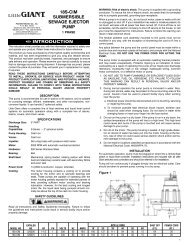
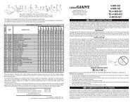
INSTALLATIONAll ACS-4 switches are factory-wired in a circuit-closed configuration.During normal operation the switch circuit is held closed by the weightof the float. When a downstream clog occurs, the float rises and opens(breaks) the electrical switch circuit to shut down the system.1. Refer to the air conditioning or refrigeration unit’s OperatingManual during installation of the ACS-4 safety switch.2. Disconnect all power to the air conditioning or refrigerationunit, both main power and the low voltage thermostat circuit.3. If an alarm circuit is required, change the switch lead wireto the configuration shown in Figure 1. To access the switchand lead wires, remove the switch cover by squeezing gentlyon both sides simultaneously at the tab locations (Figure1), then lift from the switch assembly. Remove the lead wirefrom the center terminal and connect it to the upper terminalusing needle-nosed pliers. Leave the COM (common) leadattached. This way, the switch is held open by the weight ofthe float during normal conditions, and when a downstreamclog occurs, the float rises and closes the electrical circuit toactivate the alarm. There is no need to remove the switch fromthe switch holder when changing the lead wire positions.4. To confirm correct operation, plug drain line further down linefrom switch assembly. Fill drain pan with water to activatesafety switch. Confirm that float can travel its full range with noobstructions.5. Place the “NOTICE” label included with the ACS-4 on theoutside of the access panel in a visible location.HORIZONTAL INSTALLATION:1. For plugged installation (see Figure 2 for item number andFigure 3 for installation):a. Glue the PVC Tee (Item 6) to the drain pan outlet if the outletis 1" PVC schedule 40 pipe. If it is 3/4" PVC schedule 40pipe, use the reducer bushing (Item 7) included.b. Firmly press the switch into the PVC Tee. DO NOT GLUESWITCH ASSEMBLY INTO THE TEE. If the fit is not tightenough, pipe tape may be used.c. Place the 3/4" PVC schedule 40 plug (Item 8) into the openend of the PVC Tee. Make sure this is watertight. Pipe tapeor glue may be used.d. Wire the float switch on the low voltage thermostat circuitaccording to the air conditioning or refrigeration unit’sOperating Manual.e. Test for water leaks, then test the switch by lifting the floatwhile the unit is on. To access the float, lift up the switchassembly (Figure 7). If wired correctly, the unit will stop.2. For inline installation (see Figure 2 for item number referenceand Figure 4 for installation), leave out the 3/4" plug (Item 8)and assemble the PVC Tee to the drain line.NOTE: If the assembly requires more than a 45° slope for draining,see VERTICAL INSTALLATION.Figure 23512468 79ITEM PART NO.DESCRIPTIONQTY.1 950149 Switch, Snap Action 12 950151 Switch Holder 13 950152 Switch Cover 14 950153 Switch Float Assembly 15 951983 Lead Wire Assembly, 72" 16 929458 Tee, PVC, 1" x 3/4" x 1" 17 929456 Reducer Bushing, PVC, 3/4" 18 929457 Plug, PVC, 3/4" 19* 14940159 Adaptor, PVC, 3/4" SPG x 3/4" MNPT 1*Optional adapter for pans with 3/4” NPT2
VERTICAL INSTALLATION:1. For plugged installation (see Figure 2 for item number andFigure 5 for installation):a. Remove the switch assembly (Figure 7) and place into theother 1" socket in the PVC Tee and rotate assembly 90°. Firmlypress the switch into the PVC Tee. DO NOT GLUE SWITCHASSEMBLY INTO TEE. If the fit is not tight enough, pipe tapemay be used.b. Place the 3/4" PVC schedule 40 plug (Item 8) into the openend of the PVC Tee. Make sure this is watertight. Pipe tapeor glue may be used.c. Wire the float switch on the low voltage thermostat circuitaccording to the air conditioning or refrigeration unit’sOperating Manual.d. Test for water leaks, then test the switch by lifting the floatwhile the unit is on. To access the float, lift up the switchassembly (Figure 7). If wired correctly, the unit will stop.2. For inline installation (see Figure 2 for item number referenceand Figure 6 for installation), leave out the 3/4" plug (Item 8)and assemble PVC Tee to the drain line.ALARM CIRCUITTo use the switch assembly to activate an alarm circuit instead ofshutting down the system:1. Remove the switch cover (Figure 1) to access the lead wires.2. Remove the lead wire from the center terminal and connectit to the upper terminal using needle-nosed pliers. Leave theCOM (common) lead attached.The circuit will now be held closed during normal operation.OPERATION AND MAINTENANCESwitch assemblyPVC Schedule 40reducing tee, 1” x 3/4” x 1”Drain linePVC Schedule 40 reducer bushing, 1” x 3/4”(Required for 3/4” drain lines only)PVC Schedule 40reducing tee,1” x 3/4” x 1”PVCSchedule 40plug, 3/4”A-M054Figure 4Inline Horizontal InstallationFrom drain panSwitch assemblyFrom drain panPVC Schedule 40 reducerbushing, 1” x 3/4” (Requiredfor 3/4” drain lines only)Figure 5Plugged Vertical InstallationSwitch assemblyCAUTION: THIS SAFETY SWITCH WILL NOT DETECT CLOGSUPSTREAM FROM THE INSTALLATION POINT.Clean the switch holder assembly at least every three months:1. Shut down all power to the unit and remove the switchassembly (Figure 7) from the PVC Tee.2. Clean the switch float and make sure that it moves freely.3. Clean the drain line and make sure that it is free fromobstructions.4. Replace the switch holder assembly and reconnect power.PVC Schedule 40reducing tee,1” x 3/4” x 1”To drain lineFrom drain panPVC Schedule 40 reducerbushing, 1” x 3/4” (Requiredfor 3/4” drain lines only)Figure 6Inline Vertical InstallationSwitch assemblySwitch assemblyPVC Schedule 40reducing tee, 1” x 3/4” x 1”PVC Schedule 40plug, 3/4”From drain panSwitch floatPVC TeeLift the switch assembly toremove for cleaning or testingPVC Schedule 40 reducer bushing, 1” x 3/4”(Required for 3/4” drain lines only)Figure 3Plugged Horizontal InstallationFigure 7Testing the Switch3