installation
installation
installation

Create successful ePaper yourself
Turn your PDF publications into a flip-book with our unique Google optimized e-Paper software.
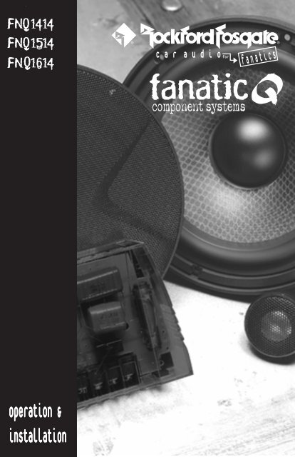
® ®c a ra u d i oforfanaticscomponent systemsoperation &<strong>installation</strong>
Dear Customer,Congratulations on your purchase of the world's finest brand of car audio speakers. AtRockford Fosgate we are fanatics about musical reproduction at its best, and we arepleased you chose our product. Through years of engineering expertise, hand craftsmanshipand critical testing procedures, we have created a wide range of products thatreproduce music with all the clarity and richness you deserve.For maximum performance we recommend you have your new Rockford Fosgateproduct installed by an Authorized Rockford Fosgate Dealer, as we provide specializedtraining through Rockford Technical Training Institute (RTTI). Please read yourwarranty and retain your receipt and original carton for possible future use.Great product and competent <strong>installation</strong>s are only a piece of the puzzle when it comesto your system. Make sure that your installer is using 100% authentic <strong>installation</strong>accessories from Connecting Punch in your <strong>installation</strong>. Connecting Punch haseverything from RCA cables and speaker wire to Power line and battery connectors.Insist on it! After all, your new system deserves nothing but the best.To add the finishing touch to your new Rockford Fosgate image order your Rockfordwearables, which include everything from T-shirts and jackets to hats and sunglasses.To get a free brochure on Rockford Fosgate products and Rockford accessories, in theU.S. call 602-967-3565 or FAX 602-967-8132. For all other countries, call +001-602-967-3565 or FAX +001-602-967-8132.PRACTICE SAFE SOUNDCONTINUOUS EXPOSURE TO SOUND PRESSURE LEVELS OVER 100dBMAY CAUSE PERMANENT HEARING LOSS. HIGH POWERED AUTOSOUNDSYSTEMS MAY PRODUCE SOUND PRESSURE LEVELS WELL OVER130dB. USE COMMON SENSE AND PRACTICE SAFE SOUND.If, after reading your manual, you still have questions regarding this product,we recommend that you see your Rockford Fosgate dealer. If you need furtherassistance, you can call us direct at 1-800-669-9899. Be sure to have your serialnumber, model number and date of purchase available when you call.The serial number can be found on the outside of the box. Please record it inthe space provided below as your permanent record. This will serve asverification of your factory warranty and may become useful in recovering yourproduct if it is ever stolen.Serial Number: ________________________________Model Number: ________________________________
T ABLE OF CONTENTSIntroduction................................................................................................ 1Package Contents ....................................................................................... 1Design Features .......................................................................................... 2Installation Considerations ........................................................................... 5Mounting Location ...................................................................................... 6Installation ................................................................................................. 7Troubleshooting ........................................................................................ 11Specifications ........................................................................................... 12Warranty Information ................................................................................ 14International Information ............................................................................ 15G ETTING STARTEDWelcome to Rockford Fosgate! This manual is designed to provide informationfor the owner, salesperson and installer. For those of you who want quickinformation on how to install this product, please turn to the InstallationSection of this manual or refer to the icons listed below. Other information canbe located by using the Table of Contents. We, at Rockford Fosgate, haveworked very hard to make sure all the information in this manual is current. But,as we are constantly finding new ways to improve our product, this informationis subject to change without notice.ITROUBLE-SNSHTOALOLTATIINONGSections markedINSTALLATIONinclude “slam dunk”wiring connectionsSections markedTROUBLESHOOTINGinclude recommendations forcuring <strong>installation</strong> problems
INTRODUCTIONThis manual provides information on the features and <strong>installation</strong> of theFanatic Q Systems. We suggest you save this manual for future reference.We strongly recommend you have your Authorized Rockford Fosgate Dealerinstall the Fanatic Q System. If you do choose to install the system yourself,please be sure to read the entire manual before beginning.PACKAGE CONTENTSFNQ1414(2) FNQ1401 TweetersIncludes 3/4" [20mm] aluminum dome tweeter,flush mount housing, surface mount housing,wedge mount housing(2) Tweeter Mounting Brackets(4) #8-32 x .500 Screws(4) #8-32 Black Nuts(8) #8 x .75 Phillips Screws(2) .110 Female Fast-on Connectors(2) .110 Male Fast-on Connectors(2) FNQ1404 4" Midrange Speakers(2) 4" Speaker Grilles(2) 4" Speaker Grille Rings(2) “RF” Speaker Grille Logos(2) FNQ142x 2-Way Crossovers(8) #8 x 1.25 Phillips Screws(20') 18 Gauge Speaker WireFNQ1514(2) FNQ1401 TweetersIncludes 3/4" [20mm] aluminum dome tweeter,flush mount housing, surface mount housing,wedge mount housing(2) Tweeter Mounting Brackets(4) #8-32 x .500 Screws(4) #8-32 Black Nuts(8) #8 x .75 Phillips Screws(2) .110 Female Fast-on Connectors(2) .110 Male Fast-on Connectors(2) FNQ1405 5 1 ⁄4" Midrange Speakers(2) 5 1 ⁄4" Speaker Grilles(2) 5 1 ⁄4" Speaker Grille Rings(2) “RF” Speaker Grille Logos(2) FNQ142x 2-Way Crossovers(8) #8 x 1.25 Phillips Screws(20') 18 Gauge Speaker WireFNQ1614(2) FNQ1401 TweetersIncludes 3/4" [20mm] aluminum dome tweeter,flush mount housing, surface mount housing,wedge mount housing(2) Tweeter Mounting Brackets(4) #8-32 x .500 Screws(4) #8-32 Black Nuts(8) #8 x .75 Phillips Screws(2) .110 Female Fast-on Connectors(2) .110 Male Fast-on Connectors(2) FNQ1406 6 1 ⁄2" Midrange Speakers(2) 6 1 ⁄2" Speaker Grilles(2) 6 1 ⁄2" Speaker Grille Rings(2) “RF” Speaker Grille Logos(2) FNQ142x 2-Way Crossovers(8) #8 x 1.25 Phillips Screws(20') 18 Gauge Speaker Wire– 1 –
DESIGN FEATURES45682711114316159121310Tweeter1. 3/4" Aluminum Dome Tweeter – To ensure accurate high frequency reproduction,the tweeter dome must be both light and strong. The Fanatic Q ComponentSystems use an aluminum dome with a silk surround. This combines the lowmass and strength of aluminum with the smoothness of silk for the ultimate inhigh frequency reproduction.2. Ferrofluid Cooling – This synthetic fluid is held in place in the magnetic gap. Thefluid bathes the voice coil allowing higher power handling and greater reliability.3. Neodymium Magnet – What good would a tweeter be if it was too big to mountin your favorite spot? The Fanatic Component Systems use a highly efficientneodymium magnet to enable a very small tweeter to have very big performance.– 2 –
DESIGN FEATURESMidrange4. Rubber Surround – The durable rubber surround withstands theextremes of the automotive environment. It also improves sound qualityby reducing 2nd and 3rd order harmonics and provides wider frequencyresponse.5. 3-Layer Glass Fiber Composite Cone – The ideal cone material wouldbe infinitely strong, very light and would have very high damping toensure great sound quality. The Fanatic Q Series Component Systemsuse a 3 layer glass fiber composite cone that is strong, light and has highinternal damping to provide excellent reproduction of sound.6. Flat Spider – The spider has the job of centering the voice coil andproviding the rear suspension for the speaker. The Fanatic Q ComponentSystems use a durable flat spider to ensure great sound with long life anddurability.7. Large 1-1/4" Voice Coil with Anodized Aluminum Former – Just likeall Rockford Fosgate woofers, all Fanatic Component System midrangedrivers use an aluminum voice coil former for more efficient dissipationof heat. Dissipating the heat is key to long life and high power handling,so go ahead and crank it up! The voice coil in the Fanatic Q seriescomponent system is larger than the voice coil in some manufacturer'swoofers.8. Proprietary Cast ABS Basket – This basket has unique cosmetics andprovides a solid platform for the midrange, reducing coloration of thesound.9. Vented Pole Piece – The pole piece extends from the back of the speakerinto the voice coil area. The Fanatic Q Component System uses a ventedpole piece to allow cool air to circulate in the voice coil gap which allowsgreater power handling and increased reliability.10. Aerovent Backplate – The curved shape of the backplate openingreduces “huffing” noises caused during high excursions. The air movingin and out of the pole piece is handled much more quietly and efficientlythan in conventional systems.– 3 –
Crossover11. Competition Quality 2-Way Butterworth Crossover – Features a 24dBper octave high-pass crossover for the tweeter and a 24dB/octave lowpasscrossover for the midrange. The steep slope of the tweeter crossovergives better power handling. The low-pass crossover provides aseamless transition between the tweeter and midrange.12. Optical Compression – This built-in protection circuit limits power tothe tweeter when the “danger” threshold is exceeded. Because it simplylimits power and doesn't shut the tweeter off, this circuit is completelyinaudible.13. Gold-Plated Screw Terminals – Terminals plated in gold for maximumresistance to corrosion ensure great sound for years to come. Theseterminals accept bare wire or 1/4" spade lug connectors.14. 0dB/–3dB/–6dB Tweeter Pad – In some <strong>installation</strong>s, you may find thatthe tweeter location is much closer to your ears than the midrange. Thispad allows you to match the tweeter level to the midrange for the bestbalance.15. Tweeter Phase Switch – This 0°/180° switch allows easy comparisonof tweeter phase without disconnecting speaker wires. Simply leave theswitch in the position that sounds best in your particular <strong>installation</strong>.16. Mylar Capacitors – These high-end, “low loss” capacitors are used tomaintain maximum sound quality.– 4 –
INSTALLATION CONSIDERATIONSTools NeededThe following is a list of some of the tools necessary for the <strong>installation</strong> of yourspeakers.Power Drill with assorted bitsTape Measure#2 Phillips ScrewdriverVoltmeterGeneral1. For safety, disconnect the negative lead from the battery prior to beginningthe <strong>installation</strong>.2. Never run wires underneath the vehicle. Running the wires inside the vehicleprovides the best protection.3. Avoid running wires over or through sharp edges. Use rubber of plasticgrommets to protect any wires routed through metal.4. Mount the speakers/crossovers away from electrical sources (other than theamplifier) i.e., power cables, electronic fuel pumps, vehicle computers,and other potential noise sources.5. Mount the speakers/crossovers away from areas of extreme heat ormoisture.Speakers1. Make sure there is an area large enough of the speaker to mount. Warning!Failure to do this can cause damage to the speaker if the speaker frameis bent during <strong>installation</strong>.2. Check to see that the location is deep enough for the speaker(s) and thelocation does not interfere with the normal operation of the vehicle.3. When mounting the speaker(s) in the door of a vehicle, make sure thespeaker(s) do not interfere with either the door or window operation.4. When mounting the speaker(s) on the rear deck of the vehicle, check theoperation of the rear hatch or trunk lid. Make sure the torsion bars and othermoving parts are not obstructed by the speaker(s) <strong>installation</strong>.• Please refer to the Specifications section of this manual for proper mountingdiameter and depth of the speaker(s).Crossovers1. Make sure there is a flat area large enough for the crossover to mount.2. For best results, mount the crossover(s) next to the amplifier for a decorativefinish to the <strong>installation</strong> and provide an easy upgrade (no new wires to run)for a bi-amp Rockford Fosgate system in the future.– 5 –
MOUNTING LOCATIONA solid front stage with a good image is one of the most difficult tasks to achievein a vehicle. No car has the optimum listening environment. This makes propersound staging very difficult to accomplish. Most speakers tend to be placedwhere they will fit easily, as opposed to where they can perform the best. Themounting location of your speakers will have a great effect on the sound qualityof your stereo system. The special care taken to place the speakers will yieldmany hours of listening enjoyment in return. Several important recommendationsshould be followed.• Place the speakers where they have a directpath to the listening area.• For the best integration between the midrangeand tweeter, the tweeter should be placed2" or lessless than 2" from the midrange. (Figure 1)• If you cannot place the tweeter less than 2"from the midrange, then place the tweetermore than 7" from the midrange. Placingthe tweeter 2"-7" from the midrange cancause destructive interference (frequencyFigure 1response problems) which will affect thespeaker's ability to reproduce the frequency range around the crossoverfrequency of the system.• Whenever possible, place the tweeter directly above or below the midrangeas this maximizes the imaging (point source) capability of the speakers.(Figure 2)Figure 2-A Figure 2-B– 6 –
® ®• Sound radiated from a “point source” has the most optimum stereo imagingbecause the separation of the acoustical centers between the midrange andtweeter for each channel is at the optimum. Figure 2-A describes ahorizontal speaker alignment. In a closed environment such as anautomobile, horizontal speaker alignment can cause severe amplitude andphase differences which will degrade not only the imaging, but also thefrequency response. This is due to the path length differences between themidrange and tweeter. Figure 2-B displays a vertical alignment between themidrange and tweeter. With a vertical alignment, the path length differencebetween the midrange and tweeter are reduced to a minimum. The resultis a negligible difference in path lengths between the midrange and tweeterregardless of the proximity of the listener to the speakers. Mounting thespeaker with minimum path length difference will ensure the best stagingand imaging possible from your audio system.INSTALLATIONMounting the MidrangeINSTALLATION1. Cut the proper size hole for the midrange/woofer.• For the FNQ1404, cut a 98.55mm (3 29 ⁄32") diameter hole• For the FNQ1405, cut a 115.57mm (4 9 ⁄16") diameter hole• For the FNQ1406, cut a 148.51mm (5 27 ⁄32") diameter hole2. Place the midrange over the mounting hole and mark the location of thescrew mounting holes.3. Remove the midrange. Drill the holes for the screws using a 1/8" drill bit.4. Route the wire through the hole.5. Attach the wires and be sure to observe the proper speaker polarity.6. Place the speaker into the hole and screw the speaker into place. Becareful not to bend the speaker frame during this step.7. Press the speaker grille into the mounting ring.– 7 –
® ®Flush Mount TweeterINSTALLATIONFlushHousingTweeterTrim RingBackPlateSurface Mount TweeterSurfaceHousingTweeter Trim Ring BackPlateWedge Mount TweeterTweeterWedgeHousing– 8 –
® ®Crossover ConnectionsINSTALLATION-6db Tweeter Level-3db Tweeter Level0db Tweeter Level0∞180∞- + - +INPUT MIDRANGE- +TWEETER–++–+(One channel ofamplifier)–• Be Sure to Maintain Speaker Polarity• 0dB Tweeter Level matches the amplitude of the tweeter to the midrange• –3dB/–6dB Tweeter Level reduces the amplitude of the tweeter –3dB or–6dB lower than the midrange. (ex. ideal for tweeters located high in doorpanels and midranges located low in the kick panel)•0°/180° Tweeter Phase matches the phase response of the tweeter to themidrange (eminent when tweeter is located away from the midrange).Leave the switch in the position that results in the best sound quality.– 9 –
® ®Bandpassing the Midrange• The Fanatic Component Systems are optimized for full range music reproduction.In cases where a subwoofer is used, the midrange can be bandpassed inorder to prevent overlapping frequencies from the midrange into the subwoofer.1.Determine the frequency range that the subwoofer will play (i.e.: 20Hz-80Hz)2.Use the low-pass crossover frequency of the subwoofer system (i.e.: 80Hz) asthe high-pass crossover frequency for the midrange3.Select the appropriate capacitor value (i.e.: 500µF) to properly bandpass themidrange4.Place the capacitor in series with the “+” terminal of the speakerINSTALLATION- + - + - +INPUT MIDRANGE TWEETERC1+–0dB–3dBSubwoofer Midrange Tweeter80Hz6dB/octave HPFrequency Speaker(Hertz) (4 ohms)C180Hz 500µF100Hz 400µF130Hz 300µF200Hz 200µF260Hz 150µF400Hz 100µF– 10 –
T ROUBLESHOOTINGTROUBLE-SHOOTINGSymptom Diagnosis RemedyNo sound fromspeakersWires between amplifier,crossover or speakers notconnected properly.Amplifier has no output.Speaker wires are shortedto each other or to the chassisof the vehicle.Check and repair or replacewiring as needed.Check system with known workingamplifier and repair or replaceas needed.Check for shorts in the wiringwith a volt/ohm meter and repairor replace wires as neededSpeakers are blown.Check system with known workingspeaker and repair or replaceas needed.Distorted soundfrom speakersTweeters “burnup” easilyIncorrect wiring betweencrossover and speakersExcessive power from amplifierEqualizer in system (ifavailable) has excessiveboost in the high frequencyrangeCheck wiring and repair or replaceas needed.Check gain settings on amplifierand readjust as necessaryCheck settings on equalizer andreadjust as necessaryEngine noise fromone or morespeakersSpeaker wires shorted tochassis of vehicle.Speaker wires are routednear radiated noise source.(Power cables, vehiclecomputers, etc.)Crossover is mounted nearradiated noise source.(Power cables, vehiclecomputers, etc.)Check for shorts in the wiringwith a volt/ohm meter and repairor replace wires as needed.Re-route speaker wiring awayfrom noise sources. (Refer tothe Installation Considerationssection of this manual.)Move crossovers away fromnoise sources. (Refer to the InstallationConsiderations sectionof this manual.)– 11 –
Wedge Mount1.562"1.24".675".965"Surface Mount1.795".25"1.00"Flush Mount.375"1.00"1.74"1.94"4.070”5.615”1.915”- + - +INPUT MIDRANGE- +TWEETER(Specifications are subject to change without notice)– 13 –
LIMITED W ARRANTY INFORMATIONRockford Corporation offers a limited warranty on Rockford Fosgate products on the followingterms:• Length of Warranty1 year on speakers 30 days on speaker B-stock (receipt required)3 years on electronics 90 days on electronic B-stock (receipt required)2 years on source units• What is CoveredThis warranty applies only to Rockford Fosgate products sold to consumers by AuthorizedRockford Fosgate Dealers in the United States of America or its possessions. Productpurchased by consumers from an Authorized Rockford Fosgate Dealer in another countryare covered only by that country’s Distributor and not by Rockford Corporation.• Who is CoveredThis warranty covers only the original purchaser of Rockford product purchased from anAuthorized Rockford Fosgate Dealer in the United States. In order to receive service, thepurchaser must provide Rockford with a copy of the receipt stating the customer name,dealer name, product purchased and date of purchase.• Products found to be defective during the warranty period will be repaired or replaced(with a product deemed to be equivalent) at Rockford's discretion.• What is Not Covered1. Damage caused by accident, abuse, improper operations, water, theft2. Any cost or expense related to the removal or re<strong>installation</strong> of product3. Service performed by anyone other than Rockford or an Authorized Rockford FosgateService Center4. Any product which has had the serial number defaced, altered, or removed5. Subsequent damage to other components6. Any product purchased outside the U.S.7. Any product not purchased from an Authorized Rockford Fosgate Dealer• Limit on Implied WarrantiesAny implied warranties including warranties of fitness for use and merchantability arelimited in duration to the period of the express warranty set forth above. Some states do notallow limitations on the length of an implied warranty, so this limitation may not apply. Noperson is authorized to assume for Rockford Fosgate any other liability in connection withthe sale of the product.• How to Obtain ServicePlease call 1-800-669-9899 for Rockford Customer Service. You must obtain an RA#(Return Authorization number) to return any product to Rockford Fosgate. You areresponsible for shipment of product to Rockford.Ship to: ElectronicsRockford CorporationWarranty Repair Department2055 E. 5th StreetTempe, AZ 85281RA#:_________________Ship to: SpeakersRockford Acoustic Design(Receiving-speakers)609 Myrtle N.W.Grand Rapids, MI 49504RA#:_________________– 14 –
® ®LEA DETENIDAMENTE LAS SIGUIENTES INSTRUCCIONES DE INSTALACIÓN DELPRODUCTO.INTRODUCCIÓNEste manual contiene información sobre la construcción, installación yfuncionamiento de los sistemas Fanatic Q. Le recomendamos que conserve elmanual para futuras consultas.ESPAÑOLEs preferible que la instalación de sistema Fanatic Q sea realizada por undistribuidor autorizado Rockford Fosgate. Si prefiere realizar la instalación ustedmismo, asegurese de leer el manual en su totalidad antes de comenzar.MONTAJE• Le mejor interacción entre tweeter y mediose consigue si no están separados entre simás de 5 cenimetros. (Figura 1)no superior a 5cmFigura 1INSTALACIÓNMontaje del altavoz de mediosINSTALLATION1. Corte el agujero para el medio/woofer.• Par el FNQ1404, corte un circulo de 98,55mm de diámetro• Par el FNQ1405, corte un circulo de 115,57mm de diámetro• Par el FNQ1406, corte un circulo de 148,51mm de diámetro– 16 –
2. Use los anillos de midrange como plantilla. Marque la posición de los tornillsde anclaje.3. Quite el anillo y perfore los agujeros con una broca de 1/8".4. Pase el cable de altavoz a través del agujero.5. Conecte los cables observando la polaridad. Mantenga los cables alejados pepartes móviles o cortantes.6. Asegure el altavoz en la abertura con los tornillos. Tenga la precaución de nodoblar el marco del altavoz en este proceso.7. Presione la rejilla en el anillo de montaje.Nivel de –6dB del AgudoNivel de –3dB del AgudoNivel de 0dB del Agudo0∞180∞- + - +INPUT MIDRANGE- +TWEETER–++–+(Un canal delamplificador)–– 17 –
® ®Veuillez lire les instrucitons suivantes pour l'<strong>installation</strong> de ces produits.INTRODUCTIONCe manuel contient des informations sur les caractéristiques et l'<strong>installation</strong> dessystèmes Fanatic Q. Nous vous proposons de garder ce manuel pour touteréférence future.Nous vous recommandons vivement de faire installaer votre système punchFanatic Q par un dealer agréé Rockford Fosgate. Si vous choisissez d'installer lesystème vous même, assurez-vous de lire ce manuel entièrement avant decommencer.EMPLACEMENT DE MONTAGE• Pour bénéficier d'une harmonie maximumentre le médium et l'aigu l'éloignement entreces deux haut-parleurs devrait être de moinsde 5 cm entre les 2 chassis. (Figure 1)moins de 5cmFRANCAISFigure 1INSTALLATIONMontage du haut-parleur médiumINSTALLATION1. Découper un trou adapté au haut-parleur médium/woofer.• Pour le FNQ1404, le diamètre du trou est de 98,55mm• Pour le FNQ1405, le diamètre du trou est de 115,57mm• Pour le FNQ1406, le diamètre du trou est de 148,51mm2. Placer médium/woofer sur le trou et repérer l'emplamcement destrous des vis.– 18 –
3. Percer les trous des vis en utilisant une mèche de 3mm.4. Faire passer les fils dans le trou central.5. Connecter les fils au haut-parleur en respectant les polarités. Eloigner les fils detoute partie tranchante ou mobile du véhicule.6. Placer le haut-parleur au-dussus du trou central. Visser le haut-parleur dans sonemplacement. Faire attention à ne pas tordre le chassis du haut-parleurdurant cette étape de montage.7. Mettre la grille dans l'anneau de montage.Niveau de l’aigu –6dBNiveau de l’aigu –3dBNiveau de l’aigu 0dB0∞180∞- + - +INPUT MIDRANGE- +TWEETER–++–+(Un canal del’amplificateur)–– 19 –
® ®Die folgende Bedienungsanleitung soll Ihnen beim Einbau eine Hilfestellunggeben.ENLEITUNGDiese Bedienungsanleitung enthält Informationen für den Gebrauch und Einbaudes Fanatic Q Systems. Wir empfehlen, diese auch für Fragen in der Zukunftsorgfältig aufzubewahren.Es ist empfehlenswert, sich das Fanatic Q System von einem AutorisiertenRockford Fosgate Fachhändler einbauen zu lassen. Sollten Sie den Einbaujedoch selber vornehmen wollen, so empfehlen wir Ihnen, die Bedienungsanleitungsorgfälitg zu lesen.EINBAUORT• Für das optimale Zusammenspiel von MittelundHochtöner, sollte der Hochtöner niemalsweiter als 5cm vorn Mitteltöner entferntmontiert werden. (Abb. 1)Abstand max. 5cm(Abb. 1)EINBAUMontage des MitteltönersINSTALLATIONDEUTSCH1. Schneiden Sie die richtige Lochgröβe für den Mitteltöner oder Midbaβ aus.• Für den FNQ1404, schneiden Sie ein 98,55cm Ø Loch• Für den FNQ1405, schneiden Sie ein 115,57cm Ø Loch• Für den FNQ1406, schneiden Sie ein 148,51cm Ø Loch2. Setzen Sie den Mitteltöner auf das Loch und markieren Sie die Löcher fürdie Schrauben.– 20 –
3. Nehmen Sie den Mitteltöner wieder ab und bohren Sie dann, mit einempassenden Bohrer, die Schraubenlöcher vor.4. Führen Sie das Kabel durch das Loch.5. Schlieβen Sie die Lautsprecherkabel an. Kontrollieren Sie, ob die Polaritätstimmt. Stellen Sie sicher, daβ das Lautsprecherkabel an keinen scharfenoder sich bewegenden Teilen anliegt.6. Plazieren Sie den Lautsprecher im Loch und befestigen Sie diesen. SeienSie dabei sehr vorsichtig, so daβ sich der Lautsprecherkorb nicht verzieht.7. Drücken Sie das Lautsprechergitter im Montagering fest.–6dB Hochtonabsenkung–3dB Hochtonabsenkung0dB Hochtonabsenkung0∞180∞- + - +INPUT MIDRANGE- +TWEETER–++–+(Ein Kanal desVerstärkers)–– 21 –
® ®Leggere le istruzioni seguenti prima dell'installazione del prodotto.INTRODUZIONEQuesto manuale fornisce informazioni sulle caratteristiche e sul installazione deisistemi Fanatic Q. Vi suggeriamo di conservare questo manuale come riferimentofuturo.Raccomandiamo fortemente che is sistema sia installato dal vostro rivenditoreRockford Fosgate. Se scegliete di procedere con l'installazione da soli, leggeteattentamente tutto il manuale prima di proseguire.POSIZIONAMENTO• Per ottenere la miglior integrazione tra tweetere midrange, vi suggeriamo di posizionare idue componenti a meno di 5 cm tra loro.(Figura 1)meno di 5 cmFigura 1INSTALLAZIONEInstallazione del MidrangeINSTALLATION1. Practicate un foro del diametro corretto per il midrange/woofer• 98,55mm per FNQ1404• 115,57mm per FNQ1405• 148,51mm per FNQ14062. Posizionate del midrange sul foro e segnate la posizione delle viti.ITALIANO– 22 –
3. Togliete midrange e forate il pannello con una puna da 3mm.4. Passate i cavi attraverso il foro.5. Collegate i cave assicurandovi di osservare la corretta polarità. Assicuratevi dimantenere i cavi lontano da parti in movimento o strutture taglienti.6. Posizionate l'altoparlante nel foro ed avvitatelo. Assicuratevi di non piegareil cestello dell'altoparlante.7. Incastrate la griglia sull'anello di fissaggio.-6db livello tweeter-3db livello tweeter-0db livello tweeter0∞180∞- + - +INPUT MIDRANGE- +TWEETER–(Un canaledell’amplificatore)++–+–– 23 –
MADE IN THE USAThis product is designed, developed and assembled in the USA by a dedicatedgroup of American workers. The majority of the components used in theconstruction of this product are produced by American companies. However,due to the global nature of their manufacturing facilities and the loudspeakerparts industry in general, some parts may be manufactured in other countries.4/98LIT9945Rockford FosgateRockford Corporation546 South Rockford DriveTempe, Arizona 85281 U.S.A.In U.S.A., (602) 967-3565In Europe, Fax (49) 8503-934014In Japan, Fax (81) 559-79-1265www.rockfordfosgate.com