BRUSHLESS IRRIGATION GENERATOR - Winco Generators
BRUSHLESS IRRIGATION GENERATOR - Winco Generators
BRUSHLESS IRRIGATION GENERATOR - Winco Generators

You also want an ePaper? Increase the reach of your titles
YUMPU automatically turns print PDFs into web optimized ePapers that Google loves.
GENERA TORS<strong>BRUSHLESS</strong><strong>IRRIGATION</strong><strong>GENERATOR</strong>INSTALLATION, OPERATION, & MAINTENANCE INSTRUCTIONS- Typical Models-<strong>GENERATOR</strong>S-over 50 Years of Leadership IM-Y82
IndexGeneral lnforma tion ........................3Installation ..............................3-4Opera tion. .............................. .4-5Preventive Maintenance .....................5Trouble Shooting .........................5-6Trouble Shooting Table. .....................6Maintenance Record. ...................... .7<strong>Winco</strong> Division of Dyna Technology, Inc., warrants that for one year from date of shipment itwill repair or replace for the original user the whole or any part of the product found upon ex-amination by <strong>Winco</strong> at its factory at 225 South Cordova Street. LeCenter, Minnesota, or by any . .actor^-~uthorized Service station to be defective in material or workmanship under normal useand service.For warranty service, please return the product within one year from date of shipment,transportation charges prepaid, to the <strong>Winco</strong> factory or to your nearest Factory-Authorized ServiceStation as listed in the 'Yellow Pages' under Generator-Electric.THERE IS NO OTHER EXPRESS WARRANTY. TO THE EXTENT PERMITTED BYLAW, ANY AND ALL IMPLIED WARRANTIES, INCLUDING THOSE OF MERCHANTA-BILITY AND FITNESS FOR A PARTICULAR PURPOSE, ARE LIMITED TO ONE YEARFROM DATE OF SHIPMENT, AND LIABILITY FOR INCIDENTAL OR CONSEQUEN-TIAL DAMAGES OR EXPENSES IS EXCLUDED. Some states do not allow limitations on theduration of an implied warranty, and some states do not allow the exclusion or limitation of incidentalor consequential damages, so the above limitation or exclusion may not apply to you. Thiswarranty gives you specific legal rights; you may have other rights which vary from state to state.<strong>Winco</strong> does not warrant engines, batteries, or certain other component parts of the productsince such items are warranted by their manufacturers.<strong>Winco</strong> does not warrant alterations or repairs which were made by someone other than the<strong>Winco</strong> factory or a Factory-Authorized Service Station and which affect the stability or reliabilityof the product.<strong>Winco</strong> does not warrant products which have been exposed to misuse and/or negligence or havebeen involved in an accident.<strong>Winco</strong> reserves the right to change or improve its products without incurring any obligations tomake such changes or improvements on products purchased previously.
General lnforma tionDescription and FeaturesThis three phase generator is designed specificallyfor the irrigation market with a forcing circuitwhich provides motor starting capability in excessof one horsepower per generator KW.The following standard features are included:1. A clearly marked insulated terminal block forconvenient load connections.2. A box with ample room for wiring.3. Drip-proof construction of generator andjunction box.4. Adjustable voltage control to compensate forline voltage drop.5. Excellent serviceability was designed intothe generator with all normal serviceableitems thoughtfully placed and easily accessiblein the junction box.6. Double sealed bearings of ample size assurelong maintenance free life.7. Voltage surge suppreksors are provided toprotect the generator from voltage transientsresulting from switching motor loads, lightning,etc.8. Screened cooling vents to prevent field micefrom entering generator.Safety InformationCAUTION: Possible damage to equipmentCaution notes indicate anycondition or practice,which if not strictly observedor remedied, couldresult in damage or destructionof the equipment.WARNING: Personal dangerWarning notes indicate anycondition or practice, whichif not strictly observed,could result in personal injuryor possible loss of life.Safety Suggestions1. Warning-A drive system guard should be installedto prevent possible personal injury.2.Always use care when operating anymechanical or powered equipment.3. Never work on the unit with the engine running.4. Keep clear of all moving parts.5. Keep your equipment clean. Periodicallycheck for loose bolts, nuts, and fasteners.UnpackingWhen unpacking the machine, be sure to inspect-- it carefully to see that no damage occurred intransit. If damage is noted, notify the transportationcompany immediately and have them writethe nature of the damage on the freight bill, sothat a claim can be filed if necessary.3LocationThis generator was designed specifically for theirrigation market to be installed outdoors near thecenter pivot irrigation pump drive engine.No special care is required; however, if the unitis to be left in the open during the off season, itshould be covered with a canvas tarp to keep outexcess water, ice and dust.MountingThe generator should be mounted on slotted railsto allow for belt adjustment. The rail should bebolted securely to a substantial base such assteel channel or concrete to prevent vibration andflexing. The mounting base should be located inan elevated position to protect from possible accumulationof moisture, mud and dirt.DriveThis generator is designed to operate at 1800 RPMonly. An engine of adequate size and equippedwith a sensitive governor is required for satisfactoryoperation of the generator. Approximately1.8-2.2 horsepower (based on engine rating anddesign) should be allowed for every 1000 watts ofgenerator capacity. That is, a 20,000 wattgenerator requires approximately 40 additionalengine horsepower.A 10,000 watt generator requires approximately20 additional engine horsepower.When determining the pulley ratio, bear in mindthat the power rating of the engine varies with thespeed and that it must maintain a nearly constantdrive speed for the generator.Since all engines have a tendency to slow downwhen a load is applied, the governor on the enginemust be sensitive enough to hold the speed constantwithin *2l/2 percent. When the electricalload connected to the generator is increased, theengine is more heavily loaded and as a result thespeed drops slightly. Although this slightdecrease in speed normally results in a lower outputvoltage when the generator is loaded, theunique forcing circuit boosts the generator voltageto compensate for this loss. Slight variationsin speed affect only the frequency of the outputvoltage. This frequency variation has no appreciableeffect in the operation of motors, lights andmost appliances; however timing devices andclocks will not keep perfect time unless thegenerator shaft is turning at exactly 1800 RPM.LoadLethal voltages are present insidethe generator junction box. Use extremecare whenever the generatorbox is opened. Consult a qualifiedelectrician for all wiring.This generator is equipped with a terminal blockfor convenient connection of electrical loads. Theoutput voltage and maximum load of each generatoris clearly marked on the nameplate. Do not
connect any load whose electrical characteristicsdiffer from those specified on the nameplate orthat exceed the rating of the generator.This four pole generator operates @ 1800 RPMShaft Speed and produces 60 Hertz (60 cycles persecond) power. Typical generator output voltagesunder no load and full load conditions are listedbelow:No Load480-490 *Volts ACFull Load @ 0.8 PF 480-490 Volts AC'Voltage is adjustable between 400 & 520 volts.NOTE:All wiring must be done in conformancewith the national code andthe state and local regulations.Generator terminal block is labeled T1, T2 andT3. 480 volt three phase power is available atthese terminals. Also 480 volts single phase isavailable between any two terminals. 277 voltssingle phase is available between any terminaland neutrallground.A ground lug is also provided on the shelf. Thegenerator neutral is bonded at the factory to thegenerator frame.Overload ProtectionThis entire irrigation generator employs componentsoperating at far less than their ratedcapacity. For example: The exciter forcing fieldbridge rectifier on the 10 KW 15 amp. generator israted to carry 122 amps. continuously and canhandle one cycle surge currents up to 700 amps.Although these components were selected toallow ample surge capacity for motor starting,overload protection such as circuit breakers orfuses should be installed to protect the equipmentfrom load faults such as single phasing andstalled motors.Installation Procedure SummaryMount the generatorInstall drive systemInstall drive safety guardsConnect loadThe generator is now connected to the system.Before proceeding, recheck all work.Final Preoperational ChecklistAre each of the unit leads insulatedand terminated properly?Is the neutral properly connected atboth the generator and the pivot junctionbox?Is the drive system aligned and adjustedproperly?Are all belts tightened?Check mounting bolts.Voltage adjust rheostat mounting nutand shaft lock nut tight.4When all checks have been made successfully,start the engine and bring it up to normaloperating speed.Carefully check the generator shaft speed. Itmust be 1800 RPM -c 45 RPM (61.5-58.5 Hz).Check generator output voltage at generator -and pivot junction box. Adjust the generator noload voltage if necessary. Apply loads-start thetower motors.If the tower motors turn backwards, interchangethe load leads connected @ T1 and T2.Recheck the generator voltage at the middletower motor terminals. To compensate for linedrop, adjust the rheostat in the generator junctionbox. Retighten shaft locknut to prevent unintentionalrotation.When voltage checks okay, replace the generatorjunction box cover and set the system controlsfor the normal operation mode.Operationage to the generator electricalinsulation.A belt or drive system guardshould be installed to protectoperators from accidental injury.The output voltage should be checked periodicallywith a portable voltmeter to insure properoperation of the generator and motor loads.Low voltage may damage both the generatorand any motors or appliances connected to it.Running the generator at excessively high speedsresults in too high voltage which may alsodamage electrical devices connected to it. Excessivelyhigh speed may also cause damage tothe rotor windings.The drive belt system must be of the correctdrive ratio and of adequate size to carry the load.The belts must be tight enough to drive thegenerator without slippage but not to the extentthat it puts excessive strain on the bearings-doingso will cause bearing failure and possibledamage to the generator.Use of Electric MotorsThe power required to start any electric motor isconsiderably more than is required for keeping itrunning once it is started. The current required to -start any motor varies with the load connected toit. An electric motor connected to an air compressor,for example, will require more than amotor to which no load is connected.
Because the heavy surge of current required forstarting motors is required for only an instant, thegenerator will not be damaged if it can bring themotor up to speed in a few seconds of time. Dueto underrated components and its unique forcing., circuit, this three phase generator has the abilityto start at least one horsepower per generatorKW.Preventive MaintenanceBearings used in this generator are prelubricatedand double sealed-no further greasing is required.If they become rough or worn they shouldbe replaced.Drive components should be checkedperiodically for wear. Keep generator cooling airintake and exhaust areas clear of obstruction. Noother routine maintenance is anticipated.TroubleshootingIf the generator does not work properly, firstcheck the conditions under which it has beenoperating.This machine uses solid state recpirim-]tifiers in various circuits. Do notuse high voltage to check for resistanceor insulation breakdown withoutfirst disconnecting all voltagesensitive devices. If necessarymake the electrical tests outlined.1. Check the speed of the generator with atachometer or frequency meter and adjustthe engine governor if necessary. If thegenerator speed cannot be kept within thespecified range when it is loaded to ratedcapacity, the engine is overloaded, or is notworking properly or the engine speed governoris not sensitive enough to hold the speedconstant over the generator load range.2. Check the generator nameplate and specificationsfor maximum safe load. If you areuncertain about the amount of load, have itchecked with an ammeter and voltmeter.3. Check for.sufficient ventilation. Be sure allventilation holes and slots are cleanedperiodically.4. If no output voltage is obtained at the outputwires, disconnect all electrical loads fromthe AC term block. If the generator operatesproperly with these wires disconnected,there is a short circuit in the load. Isolate andcorrect the short circuit.- 5. If no output voltage is obtained-separatelyexcite the generator as outlined below:Separate Excitation (Dynamic check)-Thegenerator can be checked by separately excitingthe exciter control field with a 12 voltautomotive battery, or by use of two "D" sizeflashlight batteries:Procedure: Locate the positive (+) lead(Marked 3) from the exciter control field (connectedto the exciter rectifier terminalmarked with a red dot or (+)). This positive(+) field lead should be disconnected fromthe rectifier and connected to the positive(+) side of the battery. The negative (-) leadfrom the exciter control field is connected toground. The negative (-) side of the batteryshould be connected to ground. With 12 voltDC excitation, output from the generatorshould be approximately 400 volts AC withthe generator turning @ 1800 RPM and noload applied.Resistance Static Checks-Rectifiers-Check with an ohmmeter by marking andremoving the lead wires from the rectifier.Connect the lead wires from the ohmmeter toadjacent rectifier terminals. A highresistance reading will be obtained when theohmmeter leads are connected one way.When they are reversed, a low resistancereading will be obtained. All adjacent terminalsshould be checked in this manner.Exciter Control Field-Disconnect positive(+) field lead. Field resistance should be approximately40 ohm. With both control fieldleads disconnected, the resistance measuredto ground should be infinity.Main Rotary Field-Disconnect one mainrotary field lead from the'main terminal point.Resistance of field should be 4 to 5 ohm andmeasure infinity to ground with both fieldsdisconnected.Exciter Rotor-Lift three exciter arm leads.Readings between any two leads should be avery low resistance. Reading between eachlead and ground should be infinity.Main Stator Winding-Disconnect load.Reading should be less than one ohm betweenany two leads. Use the ohmmeter tocheck the windings (with all leads disconnected)to the generator frame to determine ifthe winding is grounded. If a high voltagetester is available, it should be checked forgrounds at 1100 volts.
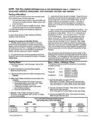
This machine uses solid state rectifiers in variouscircuits. Do not use high voltage to check forTroubleshooting Tableresistance or insulation breakdown without firstdisconnecting all voltage sensitive devices.I Symptom I Possible Cause I Remedy I -No outputLow Voltage(No load and full load)Low Voltage(Full load only)Slightly Lower Voltage(Full load only)Generator OverheatingGenerator howls or vibratesbadlv (when load is a~~liedlGenerator is noisy and vibrates(No load)Rheostat dirty or defectiveRotate knob back and forth, thenreset. Repair or replace ifnecessary.Defective exciter rectifierReolaceNo residual voltageFlash field as described on Page 7Defective or incorrectly installed exciterReplace or repairsurae -. 0-suooressor --,-,- ---- Broken lead wire to exciter field or rheostatI Repair or replaceDefective or incorrectly installed rotatingI Repair or replacesurae suooressor.I Defective exciter field I Repair or replace II Defective rotarv field I ReDair or re~lace IDefective rotating rectifierDefective exciter fieldI Defective rotarv fieldI Defective exciter armDefective output stator windingDefective compound forcing rectifierDefective comoound fieldI Broken -. or - 8~oor-forcina ., circuit connectionsGenerator overload (Defective load)Defective statorReplaceRepair or replaceI Re~air or realaceI ReDair or re~laceRepair or replaceReplaceReoair or re~laceI ReoairRepair or reduce loadReoair or reolaceI Defective rotarv field 1 Reoair or re~laceGenerator overloaded (Defective load)Cooling vents blockedLoads sinale ahasina (Defective load)Load short circuited (Defective load orirn~ro~er connection).Repair or reduceRemove obstructionsReoair broken lineI Repair load or connectionI Defective bearina I ReDlace IGenerator stator shorted internallyRotor unbalancedRotor rubbinaRepair or replaceRebalance or replaceReaair or realace defective r artsICompound Boost-I-IExciter FieldAssemblyRotatingRectifierAssembly-D--Field -- +-+-----I>-RotaryIMain(Output)Stator30"Y"I~erhinalBlock