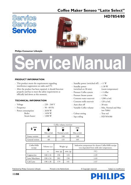
Coffee Maker Senseo âLatte Selectâ HD7854/80
Coffee Maker Senseo âLatte Selectâ HD7854/80
Coffee Maker Senseo âLatte Selectâ HD7854/80
- No tags were found...

You also want an ePaper? Increase the reach of your titles
YUMPU automatically turns print PDFs into web optimized ePapers that Google loves.
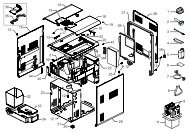
Build up: Steam circuit<strong>HD7854</strong>/<strong>80</strong>nmRefluxvalve inmilkcontainerSteamsealjjhhlliiokkVentingvalvelpWaterContainerfeBoilerThree-wayvalve withCheck valveghBrewChamberggLegend:Thermoblocka - paa - llffeekddOverpressurevalveCheck valveccbb aaLow pressure tubeHigh pressure tubeLow pressure connectionsHigh pressure connectionsSteampumpjidab cWater pump Inside the applianceElectrical circuitTemp. sensorboilerWZSWater levelsensorTemp. sensorThermo blockXCONNECTIONPCBVMilk tankdetectionsensorLid closedetectionswitchUYTDescale tooldetectorTCOBoilerLPumpMFuseFuseUSER INTERFACEPCBMSteampumpCONTROLPCBThermo blockFuseNFusePush buttons2-11
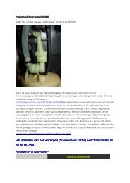
DISASSEMBLY- AND RE-ASSEMBLY ADVISERemove back cover.- Remove screws (T15) from the back cover.- Remove valve outlet.- Start at the upper side of the back cover and stick ascrewdriver between the back cover and lid cover and gentlypull the back cover from the appliance so that a little chinkbetween back cover and lid becomes visible.- Put the screwdriver into the 2 rectangular holes (snap locks)at the back and gently pull the screwdriver such away thatthe lips of the snap locks are bent outwards.- If both clicks positions are loose, it is possible to remove theback cover.- Reassemble follow steps backwards.Remove brew chamber:Removing Brew chamber head handle as follows:- Remove boiler from the snap lock position of the brewchamber.- Gently lift the backside (see picture) of the brew chamberup and unhook the two snap locks on front with help of ascrew driver.- Remove connection PCB + PCB cover.- Remove 3 way valve and electronic connectors (U & Z)from the connection PCB.- Reassemble follow above steps backwards.Remove the “lid closed” detection micro switch.Disassemble brewing head.- Unlock the snap lock which is holding the micro switchassembly. (see picture for detail)<strong>HD7854</strong>/<strong>80</strong>Remove brew chamber cover to reach user interface PCB.- To remove the brew chamber lid cover place the screwdriveron the positions (see picture) and lift the cover over thesnap locks on both positions.- The cover lid can now be lifted a little.- Remove the complete cover by unlocking the pushrod fromthe brew chamber.- The user interface PCB can be removed by unscrewing3 screws (T8)- Reassemble follow steps backwards.Removing the “de-scaling Hall sensor” detector / steamconnection- To be able to remove the Hall sensor, first unhook the spoutout of the housing.- Hall sensor assy can be taken out.- To disconnect the steam connector rotate it clockwise andpull out of the spout.To reach the components like pump, PCB, steam heaterplaced on the base.- First remove back cover, brew chamber, 3-way valve, steampump and boiler.- Remove the 4 Torx T15 screws (two at the base and two atthe housing part.- Bend the 2 click snap locks with a screwdriver (see base),the housing can now be removed.- To remove the rest of the housing unlock the 4 snap locks atthe base and gently pull of the front cover.- To reassemble follow above steps backwards.OPTIONAL (accessories)- HD7010 Latte Select Milk Container.- 4222 259 43670 <strong>Senseo</strong> Descaler kit- Gently pull out the switch assembly.- Reassemble follow above steps backwards.3-11
REPAIR INSTRUCTIONDescalingRegular descaling will prolong the life of your appliance andwill guarantee optimal brewing results for a long time.• Follow the steps in the section headed “Preparing theappliance for use” see DFU (Direction for Use manual)• Instead of only water use a mix of water and Lemon sour.• For the best result leave the mix of water and Lemon sourfor about 30 Minutes in the appliance, before you start withflushing the appliance.• To get the best results repeat above-mentioned step once ortwice.• When finished, flush the appliance twice by repeating theabove-mentioned steps only use water instead.<strong>HD7854</strong>/<strong>80</strong>Volume adjustmentThe PCB circuit board makes it possible to adjust the volumeoutput by means of pushing the one-cup and two-cup usercontrols.How to adjust the volume output:1. Be sure the boiler is filled properly, other wise perform fillprocedure see DFU for instructions.2. Switch appliance on and wait until the unit is ready tobrew.3. Select the <strong>Coffee</strong> function and selectnormal volume4. Be sure a pod holder is placed, but without a <strong>Coffee</strong>POD. (Only adjusting with plain water)5. Place a cup on the drip tray cover and push the one-cupbutton.6. When the appliance has finished it is stabilized to performthe volume adjustment.7. Empty the cup, podholder and push again for one cupsetting, measure the volume output with a graduatedbeaker. In the table you can find the requirements forthe minimum / maximum volume output cc/mL valuesdepending from the country version:One-cup setting, normal volume,Including Pod holder, water spec. (Without <strong>Coffee</strong> pod)Min. water cc/mL Max. water cc/mLFrance version 104 120General version 125 1418. Unplug the appliance from the mains.9. Press the one and two cup button simultaneously andplug the mains on.10. When above steps succeeded the main on/off switch- ,one cup- and two cup button led will be on.11. Depending if the volume has to de- or increase you haveto push the one- or two cup button.Every time you push the 1- or 2 cup button the LED willturn off for 0.5 second (feedback to user) and the pumptime will be shortened or lengthened for 0.5 secondsdepending which button was pushed.Pushing 1 cup button pump, time will be shorten with0.5 sec is approximately − 3.5 cc/mL (less coffee)Pushing 2 cup button pump, time will be lengthen with0.5 sec is approximately + 3.5 cc/mL (more coffee)When the volume has to increase with 10 cc for example,push the 2 cup button 3 times.The new value will only be stored when you switch theappliance off by pushing the main switch.(LED will turn off)12. Turn appliance on again and brew one cup, measure thevolume. In case the volume is not within specificationrepeat steps 7 – 11.13. End.4-11
REPAIR INSTRUCTIONService test routines.Sensors and buttons check mode.The <strong>Senseo</strong> is equipped with a lot of sensor and push buttons.To be able to check the function of those components aspecial service routine has been applied.1. Unplug the appliance from the mains.2. Press the on/off- and two cup button simultaneouslyand plug the mains on.3. When above steps succeeded the main on/off switch- ,one cup- and two cup button led will be on.In below table you can find which sensors or buttonscorrespondent with the indication of the user panel.For example push the one cup button and the light will beon.Selected functionOne cup buttonOn/off buttonTwo cup buttonCalc-clean button<strong>Coffee</strong> select buttonVolume select buttonClose lid detection switchHall sensor milk containerHall sensor descale toolHall sensor Tank low volumeHall sensor Tank high volumeUser panel reaction<strong>HD7854</strong>/<strong>80</strong>Automatic filling procedure:The <strong>Senseo</strong> PCB contains an automatic filling proceduresoftware routine.This fill routine is only meant for back-up.Normally the consumer has to follow the guidelines stated inthe DFU.The filling procedure functions as follows:The consumer has to fill the water container and has to plugthe appliance on the mains.When the <strong>Senseo</strong> main switch has been pushed the mainswitch led, one- and two cup led will light continuously.This is only the case when the <strong>Senseo</strong> has not finished thefilling procedure completely! (First use)This can be checked by reconnect the power cord a secondtime to the net and check if the main switch LED will blinkvery rapidly for approximately 1 second.When the consumer pushes the one or two-cup button, the<strong>Senseo</strong> will start automatically the pump to fill the boiler andafter that the Steam heater will also be filled.When the boiler is filled the pump stops pumping. (Pumptime approximately 22 seconds)When the filling procedure has been successful the softwarewill clear a Boiler_empty_flag in the Eeprom.By means of this Boiler_empty_flag the system knows theboiler is filled or not!When the <strong>Senseo</strong> is switched off or disconnected from themains, the value of the Boiler_empty_flag is stored in theEeprom chip.Restoring the Boiler_empty_flag to production default:Some times it is needed that the boiler of the <strong>Senseo</strong> have tobe emptied.This for instance in wintertime were the possibility exists thatthe boiler becomes frozen during transport e.g.For those occasions it is handy to restore the Boiler_empty_flag again to production default in the Eeprom.Bringing the <strong>Senseo</strong> back into production status, has thebenefit the flush routine will be activated automaticallywhen installed by the consumer, see topic Automatic fillingprocedure.To SET the Boiler_empty_flag can be done by:Keep the 1-cup button pressed while plugging in the powercord of the appliance.The main switch LED will blink very rapidly forapproximately 1 second.To check if the Boiler_empty_flag is really set, you shouldreconnect the power cord a second time to the net andcheck if the main switch LED will blink very rapidly forapproximately 1 second.5-11
PARTS LIST<strong>HD7854</strong>/<strong>80</strong>Pos Service code Description1234567891011121314151617181920212223242526272829303132333435363738394041424344454647484950514222 259 442104222 259 442204222 247 569204222 259 487914222 240 003204222 259 423404222 259 415104222 259 423104222 247 601824222 259 493714222 247 582704222 240 014104222 259 412214222 247 068104222 240 059904222 247 419204222 247 589104222 247 661814222 247 662014222 247 589304222 259 416604222 259 424404222 259 510714222 259 416104213 247 052504222 259 424304222 259 412304222 259 412104222 247 653314222 259 414704222 259 494514222 247 055104222 259 418704222 259 372404222 259 417504222 247 619404222 259 354404222 247 051304222 259 416204222 247 600104222 259 488614222 247 602604222 259 421604222 259 411<strong>80</strong>4222 259 426<strong>80</strong>4222 259 494414222 247 601234222 247 606614222 259 493314222 259 493514222 259 49341Padholder assy 1-cupPadholder assy 2-cupMilk TubeMilk container assyDriptray coverDriptray assyWater container assyDecalcifi cation dummy assyLasered/printed lid panelLeverPush rodSlider springUser interface PCB assyBrew chamber sealEjector pinDistribution diskCollectorSpout housing coverSpout leverSpoutSensor decalcifi cation assySteam connecting assySpouthousingSensor milk containerFootLid switch lid close detection assySteam pumpSensor water level + PCB housingValve outletValve assy zebraBackcover assyCorrugated tubeFuse assy weldedPumpThermo block assyTCO capBoiler assyNTC O-ringNTC boiler assyDriptray shaft supportPCB assy baseT-pieceVenting valve assySafety valve assyOne way valveBrew chamber assyHousingDriptray carrier1-cup buttonOn/Off button2-cup buttonDeep BlackDeep BlackTranslucent Bright WhiteTrue RedTranslucent Dark GreyTrue RedSteel SilverRedTrue RedTrue RedTrue RedCEME E151True RedTrue Red(2 pieces)ULKA HF 230 V ~50 HzV7.0 - 230 VRed LEDTrue RedTrue RedTrue RedSteel SilverSteel SilverSteel Silver6-11
EXPLODED VIEW<strong>HD7854</strong>/<strong>80</strong>512643787-11
EXPLODED VIEW<strong>HD7854</strong>/<strong>80</strong>9101311Zh12g1415168-11
EXPLODED VIEW<strong>HD7854</strong>/<strong>80</strong>p1726g2946Ufe3018aa27j1920i21T2822llSi31ab32332333cX3424Vggff35259-11
EXPLODED VIEW36<strong>HD7854</strong>/<strong>80</strong>e373839dcUVWXYZTSW284740495051y414810-11
EXPLODED VIEW<strong>HD7854</strong>/<strong>80</strong>4342llonmp42jjiikklkhhgg44eeffddccbb45aa11-11