API - Leser
API - Leser
API - Leser
- No tags were found...

Create successful ePaper yourself
Turn your PDF publications into a flip-book with our unique Google optimized e-Paper software.
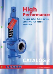
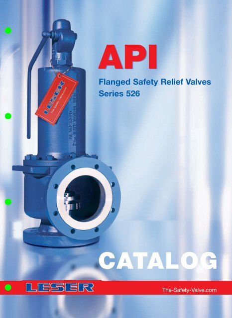
<strong>API</strong>Flanged Safety Relief ValvesSeries 526CATALOGThe-Safety-Valve.com
NH 3HCLProduct RangeLESER Safety Valves for every industrial application<strong>API</strong>HighPerformanceSeries 526Type 526CompactPerformanceCleanServiceH 2 SO 4HNO 3CriticalServiceModulateActionBestAvailability
ContentsChapter/PageGeneral 00/01Applications, General design features 00/02Valve finder 00/03How to use: Signs and symbols,Flange drillings and facings00/05How to use: Selection charts 00/06How to use: Capacity sheets 00/07LEO S/G 00/09LEO L 00/10Sour gas service 00/11Type 526 01/01Materials• Conventional design 01/02• Balanced bellows design 01/04How to order• Numbering system 01/06• Article numbers – Overview 01/08Dimensions• Metric Units 01/10• US Units 01/12Weights• Metric Units 01/14• US Units 01/15Orifice D – T 01/16• Selection chart 01/16• Article numbers, dimensions and weights 01/17• Pressure temperature ratings 01/18Flange drillings 01/72Flange facings 01/73Cap H2Closed bonnetConventional designPlain lever H3Closed bonnetConventional designPacked lever H4Closed bonnetConventional designType 526Outlet with flange rating class 300 – Overview 01/74Spare parts 01/76Available options 01/84Approvals 01/85Capacities• Steam [Metric Units + US Units] 01/86• Air [Metric Units + US Units] 01/88• Water [Metric Units + US Units] 01/90Determination of coefficient of discharge K dr /α w 01/92Options 99/01Caps and levers 99/02Caps and levers – bolted 99/04Metal seat 99/06Soft seal disc 99/08Soft seal selection 99/10Soft seal 99/11Balanced bellows 99/12High temperature equipment 99/14Lift indicator 99/15Heating jacket 99/16O-ring damper 99/18First in safetyFax OrderPlain lever H3Open bonnetConventional designCap H2Closed bonnetBalanced bellows designOptions Type 526GeneralDEFGHJKLMNPQRT
GeneralGeneral InformationLESER – <strong>API</strong> Safety ValvesThe <strong>API</strong> product group represents✓ Full range of spring loaded safety valves acc. to <strong>API</strong> 526✓ State-of-the-art design from the safety valve specialist✓ Competitive solutions for the <strong>API</strong> marketLESER´s <strong>API</strong> safety valves• Are designed to meet all applications which require <strong>API</strong>.• Open rapidly with an overpressure of max. 10 % to the fulldesign lift.• Have a maximum blowdown of minus 7 % for steam/gasservice and minus 20 % for liquid service.• Are developed in a close cooperation with plant engineersand service specialists.• Serve for protection of processes and equipment.• Are approved by all important approval organisationsworldwide which ensures the worldwide applicability e.g.:• European Community: CE-marking acc. to PressureEquipment Directive (PED) 97 / 23 / EC and EN ISO 4126-1• USA: UV-stamp acc. to ASME Section VIII Division 1,National Board certified capacities• Germany: VdTÜV approval acc. to PED, EN ISO 4126-1,TÜV SV 100 and AD 2000-Merkblatt A2• Canada: Canadian Registration Number acc. to therequirements of particular provinces• China: AQSIQ based on the approval acc. to ASMESection VIII Division 1 and AD 2000-Merkblatt A2Furthermore, all LESER <strong>API</strong> safety valves are designed, marked,produced and approved acc. to the requirements of the followingregulations (directives, codes, rules and standards).EN ISO 4126-7, EN 12266-1/-2, EN 1092 Part I and II flangingASME PTC 25, ASME-Code Sec. II, ASME B 16.34 and ASMEB16.5- flanging, <strong>API</strong> Std. 527, <strong>API</strong> RP 576AD 2000-Merkblatt A4, AD 2000-Merkblatt HP0, TRD 110,TRD 421, TRD 72100/01 LWN 480.01-E
General InformationGeneralApplicationsGeneral Design FeaturesLESER – <strong>API</strong> Safety Valvesoffer ultimate protection against overpressuresin all applications for steam, gases and liquids.LESER´s <strong>API</strong> Safety Valvescover a large variety of types, materials andoptions to fit any application:LESER’s <strong>API</strong> Series 526Safety valves present the simple safe solutionfor heavy duty applications, such as crude oilextraction, transportation and processing in• Refineries• Chemical industry• Petrochemical industry• Oil and gas – Onshore and Offshore• Vessels and piping systems• Blow-down systems• Storage tank farms• Design fully in accordance with <strong>API</strong> 526 for easy interchangeability• Complete <strong>API</strong> 526 range: valve sizes 1" through 8",orifice D through T• Materials: WCB, WCC, CF8M, WC6, LCB, LCC, 1.0619and a wide range of special materials to fulfill the requirements ofcritical applications• Special B 3 design for high back pressure applications andmaterial requirements far beyond <strong>API</strong> Standard• Fool proof design with fewer parts for built-in safety• Integral cast support brackets for easy handling and safeinstallation• Open or closed bonnet, packed or plain lifting lever or gastight cap• Flanged connections according ASME and DIN guarantee aworldwide applicability• One design and spring (single trim) for steam, gas and liquidapplications reduces the number of spare parts and ensures lowcost maintenance management.• One-piece spindle reduces friction which leads tohigh operation accuracy• Self-draining body design, avoids residues and reduces corrosionLESER´s <strong>API</strong> Safety Valvescan be customized with a great variety of options, e.g.:• Special connections specified by the customer foroptimised adaptation to the plant.• Stellited or hardened metal sealing for longer product life• Soft seat solutions for superior tightness• Stainless steel bellows for back pressure compensation• Heating jackets for applications with high viscosity fluids• Any and every part can be produced in special materialexactly to meet customer specification requirementsLWN 480.01-E00/02
GeneralValve finderHow to find the right Product GroupOrifice > FHighPerformanceRequiredOrifice letter?Orifice < FCompactPerformanceNoLiquid applicationand low capacity dependingon Valve size?YesModulateActionNo<strong>API</strong> specified application?Yes<strong>API</strong>NoCritical Service / High Corrosiveapplication?YesCriticalServiceNoClean Service application?YesCleanServiceHow to findthe right Safety ValveProduct Group00/03 LWN 480.01-E
Valve finderHow to find the right <strong>API</strong> Safety ValveGeneralStep Procedere Reference6LESER Type 5265Determination of thecode for lifting deviceCap H2 Plain lever H3 Packed lever H4 Plain lever H3Open bonnetCode for lifting deviceLifting device H2 H3 H4 H3Bonnet closed closed closed openWCB 1.0619, WC6 1.7357, LCB 2 3 4 5CF8M 1.4408 2 – 4 –4Determination of:• Flange rating class• Article No.Type 526Orifice DSelection chart150 x 150 300L x 150 300 x 150 600 x 150 900 x 300 1500 x 300 2500 x 300WCB 5262.001X–5262.002X 5262.003X–5262.004X 5262.005XWC6 – – 5267.006X 5267.007X –5267.008X 5267.009XWCB WC6T [°F]Selection chartp [bar]0 2550 75 100 150 200 250 300 350 400100090040080070030060050020040030010020010000T [°C]Specification tableArticle numbers, dimensions and weightsArticle numbersValve size 1 D 2 1 D 2 1 D 2Flange rating class 150 x 150 300L x 150 300 x 150Inlet x OutletActual Orifice diameter d 0 [mm] 14 14 14Actual Orifice area A [mm 2 ] 154 154 1540Body materialWCB 1.0619 Art.-No. 5262.001 ¤ 5262.002 ¤CF8M 1.4408 Art.-No. 5264.010 ¤ 5264.011 ¤Use 1 D 2300 x 150WC6 1.7357 Art.-No. – 5267.006 ¤LCB Art.-No. 5263.500 ¤ 5263.501 ¤0 5001000 1500 2000 3000 4000 5000 6000p [psig]3Determination ofthe materialCorrosive serviceTemperature< -29 °C< -20 °FApplicationTemperature-46 to 343 °C-50 to 650 °FNon-corrosive serviceTemperature≥ -29 °C≥ -20 °FSelection chartCF8MSelection chartCF8MLCB(ASME B16.34)Selection chartWCB/WC62Determination of therequired orifice letter(sizing)For Orifice > T see Type 441 XXL<strong>API</strong> RP 520 VALVESTAR ® (Sizing software) Capacity tableSizing, Selection andInstallation of Pressure-Relieving Devices inRefineriesPart I – Sizing andSelection<strong>API</strong> RECOMMENDEDPRACTICE 520SEVENTH EDITION,JANUARY 2000Capacities – SteamCapacities for saturated steam according to AD 2000-Merkblatt A2,based on set pressure plus 10 % overpressure.Capacities at 1 bar (14,5 psig) and below are based on 0,1 bar (1,45 psig) overpressure.)Metric Units AD 2000-Merkblatt A2 [kg/h]D E F G HOrificeAct. Orifice dia. d0 [mm] 14 14 18 22,5 28,3Act. Orifice area A 0 [mm 2 ] 154 154 254 398 629LEOS/G* [inch 2 ] 0,111 0,196 0,324 0,506 0,801Set pressure [bar]Capacities [kg/h]0,2 19 54 89 139 2210,5 42 90 149 232 3671 71 134 221 345 5462 120 217 359 561 8883 166 296 489 764 12091Application data:• Pressure, temperature• Capacity• FluidFluidLESER Type 526 offerssingle trim for steam,gas and liquids in onedesign.SteamGasesLiquidsHow to findthe right <strong>API</strong> Safety ValveLWN 480.01-E00/04
GeneralHow to useGeneral signs and symbols*✓–This option is covered by standard designAvailableNot possibleSigns and symbols for flange drillings and flange facings*Standard design, no option code required( * ) Flange dimensions except flange thickness are in accordance with flange standard (e.g. ASME B16.5)Flange thickness is smaller (max. 2 mm), see “Multiple pressure rating”–Flange drilling/facing is not possibleOption code for flange drilling and dimension, e.g. H50H50(H50)[H50]Flange drilling as specified in flange standardOuter flange diameter, flange thickness and height of flange facing may be larger, see “Dimensions”Flange dimensions except flange thickness are in accordance with standardFlange thickness is smaller (max. 2 mm), see “Multiple pressure rating”Flange drilling as specified in standard/flange thickness may be smallerOuter flange diameter is smaller than required, but complete back side facing for nut is assuredOption code for flange facing, e.g. L38L38Flange facing as specified in flange standardGeneral information concerning flange drillings and flange facingsFlange dimensions of LESER Type 526 exceed flange dimension as mentioned in ASME / ANSI B16.5 andDIN EN 1092. This exceedance is in accordance with <strong>API</strong> Standard 526, Section 2.4.DimensionsMultiplepressure ratingSmooth finishStock finishDimensions: “For some valve designs, the inlet raised face height may substantially exceed the nominal dimensionspecified in ASME / ANSI B16.5 (and DIN EN 1092). Consult the manufacturer for exact dimension.”The reason for this exceedance is:- height of nozzle placed in the inlet of valve- due to the outer diameter of the nozzle thread flange thickness has to be thicker than normalASME / ANSI B16.5 and DIN EN 1092 dimension to achieve the required pressure ratingThe flange standard shows the same drilling, facing and outer diameter for several pressure ratings, e.g. PN 16 up to PN 40Due to the pressure rating of the casting LESER fulfills the requirements for flange thickness e.g. of PN 16 but not PN 40The effective MSS SP-6 (Edition 2001) does not mention “smooth finish” anymore.In MSS SP-6 (Edition 1980) “smooth finish” is defined for finishes of contact flanges as “250 µinch (6,3 µm) AARH max.”.LESER supplies flange facings according to ASME B16.5 – 1996, paragraph 6.4.4.3:“Either a serrated concentric or serrated spiral finish resulting in service finish from 125 µinch to 250 µinch averageroughness shall be furnished.” This finish meets the requirements of MSS SP-6 (Edition 1980), which is not valid anymore!Stock finish is not defined in any technical standard. If purchase orders show “stock finish” LESER supplies standardfacing according to DIN or ASME (marked with * in table “Flange facings” of each valve series).MaterialsPlease find below a summary of material codes at LESER. Please note that- for every body material an inspection certificate 3.1 according to EN 10204 is available- many materials have a multiple inspection certificate 3.1.Material codeFlanged safety valve bodyBody material is certified with 3.1 (EN 10204) for the following materialsENASME2 Carbon steel 1.0619 WCB, WCC3 Low temperature carbon steel 1.0619 LCB, LCC, WCB, WCC4 Stainless steel 1.4408 CF8M (Charpy test at -196°C)7 High temperature carbon steel 1.7357 WC600/05 LWN 480.01-E
How to useSelection chartsGeneralThe pages 01/16 – 01/71 contain selection charts and specification tables.They specify important data about the valves based on the <strong>API</strong> 526 fifth edition 2002 like• Valve size• Body materials• Flange rating classes• Set pressure and temperature limits• Back pressure limitsProcedureStep Procedure Reference12Determination of the required flow areaand orifice letter (sizing)Determination of:• Material• Flange rating class• Article No.• <strong>API</strong> RP 520• VALVESTAR – Sizing software• Capacity tables (page 01/86 – 01/91)Selection charts (page 01/16 – 01/68) orSpecification tables (page 01/17 – 01/71)3 Determination of the material Specification tables (page 01/17 – 01/71)4 Determination of the code for lifting device Specification tables (page 01/17 – 01/71)Type 526 Orifice D 35Selection chart4150 x 150 300L x 150 300 x 150 600 x 150 900 x 300 1500 x 300 2500 x 300WCB 5262.001X–5262.002X 5262.003X–5262.004X 5262.005XWC6 – – 5267.006X 5267.007X –5267.008X 5267.009X610001p [bar]241,40 2550 75 100 150 200 250 300 350 4005WCB WC690040080070030060022 500217480 2004006300100200T [°F]T [°C]100035000 5001000 1500 2000 3000 4000 5000 6000p [psig]10ExplanationNo. Description Example123456Set pressure p 241,4 bar 3500 psigTemperature T 217 °C 480 °FRequired orifice letterDFlange rating class 2500 x 300Material WCB 1.0619Article No. (X = Code for lifting device) 5262.005XLWN 480.01-E00/06
GeneralHow to useSample Capacity sheet –How to select capacities for steam: Type 526, Valve size 1 F 2Type 526Capacities – SteamCapacities for saturated steam according to AD 2000-Merkblatt A2,based on set pressure plus 10 % overpressure.8Capacities at 1 bar (14,5 psig) and below are based on 0,1 bar(1,45 psig) overpressure.Capacities for saturated steam according to ASME Section VIII (UV),based on set pressure plus 10% overpressure.Capacities at 2,07 bar (30 psig) and below are based on 0,207 bar(3 psig) overpressure.Metric Units1AD 2000-Merkblatt A2 [kg/h]Orifice D E F 2 G HAct. Orifice dia. d0 [mm] 14 14 3 18 22,5 28,3Act. Orifice area A 0 [mm 2 ] 154 154 254 4 398 629LEOS/G* ) [inch 2 ] 0,111 0,196 5 0,324 0,506 0,801Set pressure [bar]Capacities [kg/h]0,2619 54 89 139 2210,5 42 90 149 232 3671 71 134 2217345 5462 120 217 359 561 8883 166 296 489 764 1209US Units ASME Section VIII [lb/h]Orifice D E F G HAct. Orifice dia. d0 [inch] 0,551 0,551 0,709 0,886 1,11Act. Orifice area A 0 [inch 2 ] 0,239 0,239 0,394 0,616 0,975LEOS/G* ) [inch 2 ] 0,111 0,196 0,324 0,506 0,801Set pressure [psig]Capacities [lb/h]15 183 321 531 830 131320 211 371 613 957 151530 266 469 775 1212 191740 328 577 954 1491 235950 389 686 1133 1771 2802* ) LEO S/G = LESER Effective Orifice steam/gas please refer to page 00/09Explanation Type 526, Valve size 1 F 2No. Description Metric Units US Units Example1Code AD 2000-Merkblatt A22OrificeF3Actual orifice diameter d 0 [mm] [inch] 184Actual orifice area A 0 [mm 2 ] [inch 2 ] 2545LESER Effective Orifice LEO S/G [inch 2 ] [inch 2 ] 0,3246Set pressure [bar g ] [psig] 17Capacity [kg/h] [lb/h] 2218Base of calculation see table page 00/0800/07 LWN 480.01-E
How to useGeneral8Base of calculationMetric UnitsUS UnitsCodeCapacity calculation according toAD 2000-Merkblatt A2Capacity calculation according toASME Section VIII (UV)MediaSTEAM(saturated steam)StandardconditionsSteam table IAPWS-IF97IAPWS Industrial Formulation forthe Thermodynamic Propertiesof Water and Steam[kg/h]Steam table IAPWS-IF97IAPWS Industrial Formulation forthe Thermodynamic Propertiesof Water and Steam[lb/h]AIRStandardconditions0 °C and 1013 mbar [m n 3 /h] 16 °C (60 °F) [S.C.F.M.]WATERStandardconditions20 °C (68 °F) [10 3 kg/h] 21 °C (70 °F) [US-G.P.M.]All MediaCalculationpressureSet pressure plus 10 % overpressureSet pressure plus 10 % overpressureCalculationpressure forlow set pressureCapacities at 1 bar (14,5 psig)and below are based on 0,1 bar(1,45 psig) overpressure.Capacities at 2,07 bar (30 psig)and below are based on0,207 bar (3 psig) overpressure.ExampleCapacity calculation pressureMetric UnitsUS UnitsSet pressure Capacity calculation pressure Set pressure Capacity calculation pressure10 bar 10 bar + 10% overpressure = 11 bar 145 psig 145 psig + 10% overpressure = 159,5 psig0,5 bar 0,5 bar + 0,1 bar overpressure = 0,6 bar 20 psig 20 psig + 3 psig overpressure = 23 psig5LESER Effective OrificePressure relief devices may be initially sized using theequations shown in <strong>API</strong> RP 520, sections 3.6 through 3.10as appropriate for vapors, gases, liquids, or two phase flow.These equations utilize effective coefficient of discharge (S/G0,975, L 0,650) and effective areas (acc. to <strong>API</strong> Std. 526, FifthEdition, June 2002, table 1) which are independent of anyspecificvalve design. In this way the designer can determine apreliminary pressure relief valve size. By using the LESEREffective Orifice the designer can directly select a LESERsafety relief valve after calculating the oriffice letter. In thiscase, a verification of the sizing with the selected actualorifice and the rated coefficient of discharge is not necessary.LEO S/GLESER Effective Orifice (for steam, gas and vapor) [inch 2 ] refer to page 00/09LEO LLESER Effective Orifice (for liquid) [inch 2 ] refer to page 00/10For further information refer to LESER Engineering HandbookLWN 480.01-E00/08
GeneralLEOS/GThis table is based on the rated coefficient of discharge for steams and gases of LESER safety valves certified by ASME.The appropriated K-values are shown in the column “K-value” of the table.LEO S/G [inch 2 ] = A 0 [inch 2 ] . ( K ) 0,975LEOS/GLESER Effective Orifice (for steam, gas and vapor)Orifice acc.<strong>API</strong> 526Flangerating classValve size d 0 [inch] d 0 [mm] K-valueLEOS/G[inch 2 ]% of higherorifice% of lowerorificeD 0,110 100,0% 100,0%150 – 600 1 D 2 0,551 14,0 0,455 0,111 56,8% 101,2%900 – 1500 1 1 / 2 D 2 0,551 14,0 0,455 0,111 56,8% 101,2%2500 1 1 / 2 D 3 0,551 14,0 0,455 0,111 56,8% 101,2%E 0,196 100,0% 100,0%150 – 600 1 E 2 0,551 14,0 0,801 0,196 63,9% 100,0%900 – 1500 1 1 / 2 E 2 0,551 14,0 0,801 0,196 63,9% 100,0%2500 1 1 / 2 E 3 0,551 14,0 0,801 0,196 63,9% 100,0%F 0,307 100,0% 100,0%150 – 600 1 1 / 2 F 2 0,709 18,0 0,801 0,324 64,4% 105,5%900 – 2500 1 1 / 2 F 3 0,709 18,0 0,801 0,324 64,4% 105,5%G 0,503 100,0% 100,0%150 – 900 1 1 / 2 G 3 0,886 22,5 0,801 0,506 64,5% 100,7%1500 – 2500 2 G 3 0,886 22,5 0,801 0,506 64,5% 100,7%H 0,785 100,0% 100,0%150 – 300L 1 1/ 2 H 3 1,114 28,3 0,801 0,801 62,2% 102,0%300 – 1500 2 H 3 1,114 28,3 0,801 0,801 62,2% 102,0%J 1,287 100,0% 100,0%150 – 300L 2 J 3 1,417 36,0 0,801 1,296 70,5% 100,7%300 – 1500 3 J 4 1,417 36,0 0,801 1,296 70,5% 100,7%K 1,838 100,0% 100,0%150 – 600 3 K 4 1,693 43,0 0,801 1,849 64,8% 100,6%900 – 1500 3 K 6 1,693 43,0 0,801 1,849 64,8% 100,6%L 2,853 100,0% 100,0%150 – 300L 3 L 4 2,106 53,5 0,801 2,863 79,5% 100,3%300 – 1500 4 L 6 2,106 53,5 0,801 2,863 79,5% 100,3%M 3,600 100,0% 100,0%150 – 900 4 M 6 2,374 60,3 0,801 3,637 83,8% 101,0%N 4,340 100,0% 100,0%150 – 900 4 N 6 2,598 66,0 0,801 4,357 68,3% 100,4%P 6,380 100,0% 100,0%150 – 900 4 P 6 3,150 80,0 0,801 6,401 57,9% 100,3%Q 11,050 100,0% 100,0%150 – 600 6 Q 8 4,154 105,5 0,801 11,132 69,6% 100,7%R 16,000 100,0% 100,0%150 6 R 8 4,980 126,5 0,801 16,004 61,6% 100,0%300 – 600 6 R 10 4,980 126,5 0,801 16,004 61,6% 100,0%T 26,000 100,0% 100,0%150 – 300 8 T 10 6,358 161,5 0,801 26,085 100,3%00/09 LWN 480.01-E
LEOLGeneralThis table is based on the rated coefficient of discharge for steams and gases of LESER safety valves certified by ASME.The appropriated K-values are shown in the column “K-value” of the table.LEO L [inch 2 ] = A 0 [inch 2 ] . ( K ) 0,650LEO L LESER Effective Orifice (for liquid)Orifice acc.<strong>API</strong> 526Flangerating classValve size d 0 [inch] d 0 [mm] K-valueLEOL[inch 2 ]% of higherorifice% of lowerorificeD 0,110 100,0% 100,0%150 – 600 1 D 2 0,551 14,0 0,343 0,126 64,2% 114,5%900 – 1500 1 1 / 2 D 2 0,551 14,0 0,343 0,126 64,2% 114,5%2500 1 1 / 2 D 3 0,551 14,0 0,343 0,126 64,2% 114,5%E 0,196 100,0% 100,0%150 – 600 1 E 2 0,551 14,0 0,579 0,213 69,2% 108,4%900 – 1500 1 1 / 2 E 2 0,551 14,0 0,579 0,213 69,2% 108,4%2500 1 1 / 2 E 3 0,551 14,0 0,579 0,213 69,2% 108,4%F 0,307 100,0% 100,0%150 – 600 1 1 / 2 F 2 0,709 18,0 0,579 0,351 69,8% 114,4%900 – 2500 1 1 / 2 F 3 0,709 18,0 0,579 0,351 69,8% 114,4%G 0,503 100,0% 100,0%150 – 900 1 1 / 2 G 3 0,886 22,5 0,579 0,549 69,9% 109,1%1500 – 2500 2 G 3 0,886 22,5 0,579 0,549 69,9% 109,1%H 0,785 100,0% 100,0%150 – 300L 1 1/ 2 H 3 1,114 28,3 0,579 0,868 67,5% 110,6%300 – 1500 2 H 3 1,114 28,3 0,579 0,868 67,5% 110,6%J 1,287 100,0% 100,0%150 – 300L 2 J 3 1,417 36,0 0,579 1,405 76,5% 109,2%300 – 1500 3 J 4 1,417 36,0 0,579 1,405 76,5% 109,2%K 1,838 100,0% 100,0%150 – 600 3 K 4 1,693 43,0 0,579 2,005 70,3% 109,1%900 – 1500 3 K 6 1,693 43,0 0,579 2,005 70,3% 109,1%L 2,853 100,0% 100,0%150 – 300L 3 L 4 2,106 53,5 0,579 3,104 86,2% 108,8%300 – 1500 4 L 6 2,106 53,5 0,579 3,104 86,2% 108,8%M 3,600 100,0% 100,0%150 – 900 4 M 6 2,374 60,3 0,579 3,943 90,9% 109,5%N 4,340 100,0% 100,0%150 – 900 4 N 6 2,598 66,0 0,579 4,724 74,0% 108,8%P 6,380 100,0% 100,0%150 – 900 4 P 6 3,150 80,0 0,579 6,940 62,8% 108,8%Q 11,050 100,0% 100,0%150 – 600 6 Q 8 4,154 105,5 0,579 12,070 75,4% 109,2%R 16,000 100,0% 100,0%150 6 R 8 4,980 126,5 0,579 17,353 66,7% 108,5%300 – 600 6 R 10 4,980 126,5 0,579 17,353 66,7% 108,5%T 26,000 100,0% 100,0%150 – 300 8 T 10 6,358 161,5 0,579 28,283 108,8%LWN 480.01-E00/10
GeneralSour gas service (H 2 S)Normative basisIn accordance with NACE standard MR 0175-2003 sour gas service means the presence of H 2 S in the following conditions:Part 1.4.1.1.:All gas, gas condensate, and sour crude oil – When the partial pressure of H 2 S in a wet (water as a liquid)gas phase of a gas, gas condensate, or crude oil system is equal to or exceeds 0,003 bar g (0,05 psia)Exceptions are:Part 1.4.2.1.: Low-pressure gas: When the total pressure is lower than 4,5 bar a (65psia)Part 1.4.2.2.: Low-pressure oil and gas multiphase systems: …Other Sour gas standards:NACE MR 0103-2003: Materials resistance to sulfide stress cracking in corrosive petroleum refining environments.DIN EN ISO 15156-1: Petroleum and natural gas industries – Materials for use in H 2 S-containing environments in oiland gas production – Part 1: General principles for selection of cracking-resistant materials(ISO 15156-1:2001)MiscellaneousWorkstandards: Please refer to LWN 001.91General requirements for sour gas serviceThe above mentioned standards require a maximum hardness of 22 HRC for the most steels.For the actual requirements of a specific material please refer to the applied standard.LESER sour gas levelGeneral: Sour gas material requirements must be fulfilled if pressure and partial pressure conditions according tothe applied standard exist.Based on these general statement LESER defines two sour gas level for safety valves:Part definitionLevel 1 Level 2Contact with the medium inclosed positionContact with the medium inopened positionConventional Balanced bellows Conventional Balanced bellowsContact areaPressure requirements Set pressure ≥ 4,5 bar a (65psia) Back pressure ≥ 4,5 bar a (65psia)Safety valve operation closed closed / openedParts concernedNecessary material modificationType526252635267BodymaterialWCB 1.0619LCBWC6 1.7357ConventionaldesignBalancedbellows designNozzleDiscNozzleDiscAllNozzleDiscBonnet spacerBellowsDesign Part Material Option code Material Option codeConventionalBalancedbellowsDiscDisc1.4404 / 316Lstellited1.4404 / 316LstellitedJ25J25Please choose balancedbellows design1.4404 / 316LJ25stellitedBellows 1.4571 / 316Ti J78 1.4571 / 316Ti J785264 CF8M 1.4408Conventional No modification required No modification requiredBalancedbellowsBellows 1.4571 / 316Ti J78 1.4571 / 316Ti J7800/11 LWN 480.01-E
TypeType 526Type 526Packed lever H4Closed bonnetConventional design526Flanged Safety Relief Valves– spring loadedContentsChapter/PageMaterials• Conventional design 01/02• Balanced bellows design 01/04How to order• Numbering system 01/06• Article numbers 01/08Dimensions• Metric Units 01/10• US Units 01/12Weights• Metric Units 01/14• US Units 01/15Orifice [ D – T]• Selection charts /Article numbers, dimensions and weights 01/16• Pressure temperature ratings[Metric Units + US Units] 01/18Flange drillings 01/72Flange facings 01/73Outlet with flange rating class 300 01/74Spare parts 01/76Available options 01/84Approvals 01/85Capacities• Steam [Metric Units + US Units] 01/86• Air [Metric Units + US Units] 01/88• Water [Metric Units + US Units] 01/90LWN 480.01-E01/01
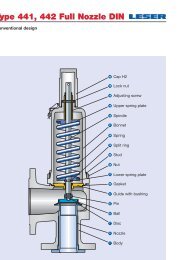
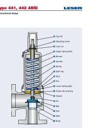
Type 526Conventional designType 5264019186916Cap H2Lock nutAdjusting screwNeedle bearingSpring plate54 Spring12 Spindle9 Bonnet1417Split ringSpring plate55 Stud56 NutPlug 648 Guide60 Gasket22Lift stopper57 Ball66 Screw61 Ball73Lock screw7 Disc6 Adjusting ring1 Body5 Nozzle01/02 LWN 480.01-E
Type 526Conventional designItemMaterialsComponentStandard Service Type 5262Trim: StandardCorrosive Service Type 5264Trim: StandardType 5267Trim: StandardType 5263Trim: StandardType 5261 Body1.0619 1.4408 1.7357SA 216 WCB SA 315 CF8M SA 217 WC6 SA 352 LCB5 Nozzle 1) 1.4404 1.4404 1.4404 stellited 1.4404316 L 316L 316L stellited 316L6 Adjusting ring7 Disc8 Guide9 Bonnet12 Spindle14 Split ring16 / 17 Spring plate18Adjusting screwwith bushing19 Lock nut22 Lift stopper40 Cap H254 Spring55 Stud56 Nut57 Ball60 Gasket61 Ball64 Plug66 Screw69 Needle bearing73 Lock screw1.4408 1.4408 1.4404 1.4408CF8M CF8M 316L CF8M1.4122 1.4404 stellited 1.4122 1.4122Hardened stainless steel 316L stellited Hardened stainless steel Hardened stainless steel1.4404 1.4404 1.4404 1.4404316 L 316L 316L 316L1.0619 1.4404, 1.4571 1.7357SA 216 WCB SA 479 316L, 316Ti SA 217 WC6 SA 352 LCB1.4021 1.4021 1.4021 1.4021420 420 420 4201.4104 1.4404 1.4104 1.4104Chrome steel 316L Chrome steel Chrome steel1.0718 1.4404 1.0718 1.0718Steel 316L Steel Steel1.4104 1.4404 tenifer 1.4104 1.4104Chrome steel 316L tenifer Chrome steel Chrome steelPTFE with 15% Glas PTFE 15% Glas PTFE 15% Glas PTFE 15% Glas– " – – " – – " – – " –1.0718 1.4404 1.0718 1.0718Steel 316L Steel Steel1.4404 1.4404 1.4404 1.4404316L 316L 316L 316L1.0718 1.4404 1.0718 1.0718Steel 316L Steel Steel1.8159 1.4310 1.8159 1.8159High temp. alloy steel Stainless steel High temp. alloy steel High temp. alloy steel1.4401 1.4401 1.4401 1.4401B8M B8M B8M B8M1.4401 1.4401 1.4401 1.44018M 8M 8M 8M1.4401 1.4401 1.4401 1.4401316 316 316 316Graphite / 1.4401 Graphite / 1.4401 Graphite / 1.4401 Graphite / 1.4401Graphite / 316 Graphite / 316 Graphite / 316 Graphite / 3161.3541 1.4401 1.3541 1.3541Hardened stainless steel 316 Hardened stainless steel Hardened stainless steelSteel 1.4401 Steel Steel– " – B8M – " – – " –1.4401 1.4401 1.4401 1.4401B8M B8M B8M B8M1.4404 1.4404 1.4404 1.4404316L 316 L 316L 316L1.4404 1.4404 1.4404 1.44048M 8M 8M 8M1)Stellited sealing surfaces please refer to page 99/06Please notice:Special materials:- Modifications reserved by LESER Body and trim available in various materials (Monel ® , Hastelloy ® ...).- LESER can upgrade materials without notice For nozzle and disc machined from the bar a short lead time is possible.- Every part can be replaced by other material acc. to customer specification.LWN 480.01-E01/03
Type 526Balanced bellows designType 5264019186916Cap H2Lock nutAdjusting screwNeedle bearingSpring plate54 Spring12 Spindle9 Bonnet1417Split ringSpring plate55 Stud56 Nut8 Guide60 Gasket11Bonnet spacer15 Bellows57 Ball66 Screw61 Ball7 Disc73Lock screw6 Adjusting ring1 Body5 Nozzle01/04 LWN 480.01-E
Type 526Balanced bellows designMaterialsItemComponent1 BodyStandard Service Type 5262Trim: StandardCorrosive Service Type 5264Trim: StandardType 5267Trim: Standard1.0619 1.4408 1.7357Type 5263Trim: StandardSA 216 WCB SA 315 CF8M SA 217 WC6 SA 352 LCB5 Nozzle 2) 1.4404 1.4404 1.4404 stellited 1.4404316 L 316L 316L stellited 316L6 Adjusting ring7 Disc8 Guide9BonnetValve size6 R 10, 8T101.4408 1.4408 1.4404 1.4408CF8M CF8M 316L CF8M1.4122 1.4404 stellited 1.4122 1.4122Hardened stainless steel 316L stellited Hardened stainless steel Hardened stainless steel1.4404 1.4404 1.4404 1.4404316 L 316L 316L 316L1.0619 1.4404, 1.4571 1.7357SA 216 WCB SA 479 316L, 316Ti SA 217 WC6 SA 352 LCB1.0305 1.4571 1.0305 1.0305Steel SA 479 316Ti Steel Steel11 Bonnet spacer 1) 1.0460 1.4404 1.4404 1.4404Carbon steel SA 479 316L SA 479 316L 316L12 Spindle14 Split ring15 Bellows16 / 17 Spring plate18Adjusting screwwith bushing19 Lock nut22 Lift stopper40 Cap H254 Spring55 Stud56 Nut57 Ball60 Gasket61 Ball66 Screw69 Needle bearing73 Lock screw1.4021 1.4021 1.4021 1.4021420 420 420 4201.4104 1.4404 1.4104 1.4104Chrome steel 316L Chrome steel Chrome steel1.4571 1.4571 1.4571 1.4571316 Ti 316 Ti 316 Ti 316 Ti1.0718 1.4404 1.0718 1.0718Steel 316L Steel Steel1.4104 1.4404 tenifer 1.4104 1.4104Chrome steel 316L tenifer Chrome steel Chrome steelPTFE with 15% Glas PTFE 15% Glas PTFE 15% Glas PTFE 15% Glas– " – – " – – " – – " –1.0718 1.4404 1.0718 1.0718Steel 316L Steel Steel1.4404 1.4404 1.4404 1.4404316L 316L 316L 316L1.0718 1.4404 1.0718 1.0718Steel 316L Steel Steel1.8159 1.4310 1.8159 1.8159High temp. alloy steel Stainless steel High temp. alloy steel High temp. alloy steel1.4401 1.4401 1.7709 1.4401B8M B8M B16 B8M1.4401 1.4401 1.7258 1.44018M 8M 7M 8M1.4401 1.4401 1.4401 1.4401316 316 316 316Graphite / 1.4401 Graphite / 1.4401 Graphite / 1.4401 Graphite / 1.4401Graphite / 316 Graphite / 316 Graphite / 316 Graphite / 3161.3541 1.4401 1.3541 1.3541Hardened stainless steel 316 Hardened stainless steel Hardened stainless steel1.4401 1.4401 1.4401 1.4401B8M B8M B8M B8M1.4404 1.4404 1.4404 1.4404316L 316 L 316L 316L1.4404 1.4404 1.4404 1.44048M 8M 8M 8MType 5261)Valve size 6 R 10 and 8 T 10 without bonnet spacer2)Stellited sealing surfaces please refer to page 99/06Please notice:Special materials:- Modifications reserved by LESER Body and trim available in various materials (Monel ® , Hastelloy ® ...).- LESER can upgrade materials without notice For nozzle and disc machined from the bar a short lead time is possible.- Every part can be replaced by other material acc. to customer specification.LWN 480.01-E01/05
Type 526How to order – Numbering systemType 5261 2 3Article Number Set Pressure Connections1 2 3 4526 2 . 001 2Please state unit (in gauge)!Please do not exceed the pressurerange defined in the spring charts.If different from <strong>API</strong> 526 Standardplease refer to page 01/72.1Valve Type 5262Material codeCodeBody + bonnet material2 WCB 1.06193 LCB4 CF8M 1.44087 WC6 1.73573Valve codeIdentifies valve size, body material,orifice and flange class. Refer topage 01/08 and 01/09.4Code Lifting lever2 screwed cap H23 plain lever H34 packed lever H4plain lever with5open bonnetH35262.0012Article No.5 bargSet PressureH45Connections01/06 LWN 480.01-E
Type 5264 5 6Options Documentation Code and MediumType 526Type 526Option codePlease select requested documentation:1 2• RJ groove inletL58• O-ring-discCR “K” J21EPDM “D” J22FKM “L” J23FFKM “C” J20• Disc 1.4404 / 316L stellited J25• Nozzle 1.4404 / 316L stellited L62• Stainless steel bellows- open bonnet J68- closed bonnet J78- high temperature equipment J88(Type 5267 only)• Stainless steel springX04• Adaptor for lift indicator H4 J39• Lift indicatorJ93• Test gag- cap H2 J70- packed lever H4 J69• Free of oil and greaseJ85• Materials- NACE H01• Heating jacket- Couplings G 3 / 8 H29G 3 / 4 H30- Flanges DN 15 H31DN 25 H321 / 2" class 150 K311" class 150 K32- Bonnet spacer H33• Bolted cap H1 K01• Bolted lifting device H6 K06Inspections, tests: Option CodeDIN EN 10204-3.2: TÜV-NordCertificate for test pressure M33LESER Certificate for GlobalApplication- Inspection certificate 3.1 acc.to DIN EN 10204- Declaration of conformity acc.to PED 97/23/ECMaterial test certificate:DIN EN 10204-3.1PartBodyBonnetCap / lever coverNozzleDiscStudsNutsH03Option codeH01L30L31L59L23N07N08123 . 1Code1. ASME Section VIII2. CE / VdTUEV3. ASME Section VIII+ CE / VdTUEVMedium.1 Gases.2 Liquids.3 Steam.0 Steam / Gases / Liquids(valid only for CE / VdTUEV)Option code applies onlyif not standardJ22 H01 L303.1OptionsDocumentationCode and MediumLWN 480.01-E01/07
Type 526Article numbers – OverviewType 526Article numbersMaterial WCB CF8M WC6 LCB WCB CF8M WC6 LCB WCB CF8M WC6 LCB1.0619 1.4408 1.7357 1.0619 1.4408 1.7357 1.0619 1.4408 1.7357Flange class 150 x 150 300L x 150 300 x 150Valve size 1 D 2 1 D 2 1 D 2D5262. 5264. – 5263. Use 1 D 25262. 5264. 5267. 5263.001 ¤ 010 ¤ 500 ¤ 300 x 150002 ¤ 011 ¤ 006 ¤ 501 ¤1 E 2 1 E 2 1 E 2E5262. 5264. – 5263. Use 1 E 25262. 5264. 5267. 5263.015 ¤ 024 ¤ 505 ¤ 300 x 150016 ¤ 025 ¤ 020 ¤ 506 ¤1 1 / 2 F 2 1 1 / 2 F 2 1 1 / 2 F 2F5262. 5264. – 5263. 5262. 5264. – 5263. 5262. 5264. 5267. 5263.029 ¤ 039 ¤ 510 ¤ 030 ¤ 040 ¤ 511 ¤ 031 ¤ 041 ¤ 035 ¤ 512 ¤G1 1 / 2 G 3 1 1 / 2 G 3 1 1 / 2 G 35262. 5264. – 5263. 5262. 5264. – 5263. 5262. 5264. 5267. 5263.045 ¤ 110 ¤ 516 ¤ 046 ¤ 111 ¤ 517 ¤ 047 ¤ 112 ¤ 052 ¤ 518 ¤Flange class 150 x 150 300L x 150 300 x 150Valve size 1 1 / 2 H 3 1 1 / 2 H 3 2 H 3H5262. 5264. – 5263. 5262. 5264. – 5263. 5262. 5264. 5267. 5263.142 ¤ 152 ¤ 523 ¤ 143 ¤ 153 ¤ 524 ¤ 144 ¤ 154 ¤ 148 ¤ 525 ¤J2 J 3 2 J 3 3 J 45262. 5264. – 5263. 5262. 5264. – 5263. 5262. 5264. 5267. 5263.162 ¤ 196 ¤ 529 ¤ 163 ¤ 197 ¤ 530 ¤ 164 ¤ 198 ¤ 168 ¤ 531 ¤3 K 4 3 K 4 3 K 4K5262. 5264. – 5263. Use 3 K 45262. 5264. 5267. 5263.202 ¤ 211 ¤ 535 ¤ 300 x 150203 ¤ 212 ¤ 207 ¤ 536 ¤Flange class 150 x 150 300L x 150 300 x 150Valve size 3 L 4 3 L 4 4 L 6L5262. 5264. – 5263. 5262. 5264. – 5263. 5262. 5264. 5267. 5263.232 ¤ 242 ¤ 540 ¤ 233 ¤ 243 ¤ 541 ¤ 234 ¤ 244 ¤ 238 ¤ 542 ¤MNPQRT4 M 6 4 M 6 4 M 65262. 5264. – 5263. Use 4 M 65262. 5264. 5267. 5263.580 ¤ 587 ¤ 546 ¤ 300 x 150581 ¤ 588 ¤ 584 ¤ 547 ¤4 N 6 4 N 6 4 N 65262. 5264. – 5263. Use 4 N 65262. 5264. 5267. 5263.590 ¤ 597 ¤ 550 ¤ 300 x 150591 ¤ 598 ¤ 594 ¤ 551 ¤4 P 6 4 P 6 4 P 65262. 5264. – 5263. 5262. 5264. – 5263. 5262. 5264. 5267. 5263.645 ¤ 653 ¤ 554 ¤ 646 ¤ 654 ¤ 555 ¤ 647 ¤ 655 ¤ 650 ¤ 556 ¤6 Q 8 6 Q 8 6 Q 85262. 5264. – 5263. Use 6 Q 85262. 5264. 5267. 5263.657 ¤ 662 ¤ 559 ¤ 300 x 150658 ¤ 663 ¤ 660 ¤ 560 ¤6 R 8 6 R 8 6 R 105262. 5264. – 5263. 5262. 5264. 5267. 5263. 5262. 5264. – 5263.665 ¤ 671 ¤ 562 ¤ 666 ¤ 672 ¤ 669 ¤ 563 ¤ 667 ¤ 673 ¤ 564 ¤8 T 10 8 T 10 8 T 105262. 5264. – 5263. Use 8 T 105262. 5264. 5267. 5263.675 ¤ 678 ¤ 566 ¤ 300 x 150676 ¤ 679 ¤ 677 ¤ 567 ¤01/08 LWN 480.01-E
Type 526Article numbers – OverviewArticle numbersMaterial WCB CF8M WC6 LCB WCB CF8M WC6 LCB WCB CF8M WC6 LCB WCB CF8M WC6 LCB1.0619 1.4408 1.7357 1.0619 1.4408 1.7357 1.0619 1.4408 1.7357 1.0619 1.4408 1.7357Flange class 600 x 150 900 x 300 1500 x 300 2500 x 300Valve size 1 D 2 1 1 / 2 D 2 1 1 / 2 D 2 1 1 / 2 D 3DEFG5262. 5264. 5267. 5263. Use 1 1 / 2 D 2 5262. 5264. 5267. 5263. 5262. 5264. 5267. 5263.003 ¤ 012 ¤ 007 ¤ 502 ¤ 1500 x 300 004 ¤ 013 ¤ 008 ¤ 503 ¤ 005 ¤ 014 ¤ 009 ¤ 504 ¤1 E 2 1 1 / 2 E 2 1 1 / 2 E 2 1 1 / 2 E 35262. 5264. 5267. 5263. Use 1 1 / 2 E 2 5262. 5264. 5267. 5263. 5262. 5264. 5267. 5263.017 ¤ 026 ¤ 021 ¤ 507 ¤ 1500 x 300 018 ¤ 027 ¤ 022 ¤ 508 ¤ 019 ¤ 028 ¤ 023 ¤ 509 ¤1 1 / 2 F 2 1 1 / 2 F 3 1 1 / 2 F 3 1 1 / 2 F 35262. 5264. 5267. 5263. Use 1 1 / 2 F 3 5262. 5264. 5267. 5263. 5262. 5264. 5267. 5263.032 ¤ 042 ¤ 036 ¤ 513 ¤ 1500 x 300 033 ¤ 043 ¤ 037 ¤ 514 ¤ 034 ¤ 044 ¤ 038 ¤ 515 ¤1 1 / 2 G 3 1 1 / 2 G 3 2 G 3 2 G 35262. 5264. 5267. 5263. 5262. 5264. 5267. 5263. 5262. 5264. 5267. 5263. 5262. 5264. 5267. 5263.048 ¤ 113 ¤ 053 ¤ 519 ¤ 049 ¤ 114 ¤ 054 ¤ 520 ¤ 050 ¤ 115 ¤ 055 ¤ 521 ¤ 051 ¤ 116 ¤ 056 ¤ 522 ¤Flange class 600 x 150 900 x 150 1500 x 300Valve size 2 H 3 2 H 3 2 H 3H5262. 5264. 5267. 5263. 5262. 5264. 5267. 5263. 5262. 5264. 5267. 5263.145 ¤ 155 ¤ 149 ¤ 526 ¤ 146 ¤ 156 ¤ 150 ¤ 527 ¤ 147 ¤ 157 ¤ 151 ¤ 528 ¤Type 526J3 J 4 3 J 4 3 J 45262. 5264. 5267. 5263. 5262. 5264. 5267. 5263. 5262. 5264. 5267. 5263.165 ¤ 199 ¤ 169 ¤ 532 ¤ 166 ¤ 200 ¤ 170 ¤ 533 ¤ 167 ¤ 201 ¤ 171 ¤ 534 ¤K3 K 4 3 K 6 3 K 65262. 5264. 5267. 5263. 5262. 5264. 5267. 5263. 5262. 5264. 5267. 5263.204 ¤ 213 ¤ 208 ¤ 537 ¤ 205 ¤ 214 ¤ 209 ¤ 538 ¤ 206 ¤ 215 ¤ 210 ¤ 539 ¤Flange class 600 x 150 900 x 150 1500 x 150Valve size 4 L 6 4 L 6 4 L 6L5262. 5264. 5267. 5263. 5262. 5264. 5267. 5263. 5262. – 5267. 5263.235 ¤ 245 ¤ 239 ¤ 543 ¤ 236 ¤ 246 ¤ 240 ¤ 544 ¤ 237 ¤ 241 ¤ 545 ¤MNPQ4 M 6 4 M 65262. 5264. 5267. 5263. 5262. – 5267. 5263.582 ¤ 589 ¤ 585 ¤ 548 ¤ 583 ¤ 586 ¤ 549 ¤4 N 6 4 N 65262. 5264. 5267. 5263. 5262. – 5267. 5263.592 ¤ 599 ¤ 595 ¤ 552 ¤ 593 ¤ 596 ¤ 553 ¤4 P 6 4 P 65262. 5264. 5267. 5263. 5262. – 5267. 5263.648 ¤ 656 ¤ 651 ¤ 557 ¤ 649 ¤ 652 ¤ 558 ¤6 Q 85262. 5264. 5267. 5263.659 ¤ 664 ¤ 661 ¤ 561 ¤RT6 R 105262. 5264. 5267. 5263.668 ¤ 674 ¤ 670 ¤ 565 ¤8 T 10– – – –¤)Please add code for the required cap or lifting device.Code for lifting device H2 H3 H4 H3Bonnet closed closed closed openWCB 1.0619, WC6 1.7357, LCB 2 3 4 5CF8M 1.4408 2 – 4 –LWN 480.01-E01/09
Type 526DimensionsType 526Metric UnitsSafety valve dimensions [mm] a b s Hmax.Hmax.withbellowsa b s Hmax.Hmax.withbellowsa b s Hmax.Support brackets [mm] A B C D E A B C D E A B C D EFlange rating class 150 x 150 300L x 150 300 x 150Valve size 1 D 2 1 D 2 1 D 2DEFGd 0 [mm] 14 105 114 30 440 465 Please see 1 D 2105 114 30 440 465A 0 [mm 2 ] 154 130 – Ø 14 132 16 300 x 150130 – Ø 14 132 161 E 2 1 E 2 1 E 2d 0 [mm] 14 105 114 30 440 465 Please see 1 E 2105 114 30 440 465A 0 [mm 2 ] 154 130 – Ø 14 132 16 300 x 150130 – Ø14 132 161 1 / 2 F 2 1 1 / 2 F 2 1 1 / 2 F 2d 0 [mm] 18 124 121 32 536 561 124 121 32 536 561 124 152 35 536 561A 0 [mm 2 ] 254 162 – Ø 14 148 16 162 – Ø 14 148 16 162 – Ø 14 148 161 1 / 2 G 3 1 1 / 2 G 3 1 1 / 2 G 3d 0 [mm] 22,5 124 121 32 536 574 124 121 32 536 574 124 152 35 536 574A 0 [mm 2 ] 398 162 – Ø 14 148 16 162 – Ø 14 148 16 162 – Ø 14 148 16Flange rating class 150 x 150 300L x 150 300 x 150Valve size 1 1 / 2 H 3 1 1 / 2 H 3 2 H 3HJKd 0 [mm] 28,3 130 124 38 542 580 130 124 38 542 580 130 124 43 666 692A 0 [mm 2 ] 629 162 – Ø 14 155 16 162 – Ø 14 155 16 184 110 Ø 14 177 162 J 3 2 J 3 2 J 3d 0 [mm] 36 137 124 49 673 722 137 124 49 673 722 184 181 49 786 824A 0 [mm 2 ] 1018 184 110 Ø 14 184 16 184 110 Ø 14 184 16 238 140 Ø 18 234 253 K 4 3 K 4 3 K 4WCB, LCB, d 0 [mm] 43 156 162 49 758 796 Please see 3 K 4156 162 49 758 796CF8M (WC6) A 0 [mm 2 ] 1452 238 140 Ø 18 206 25 300 x 150238 140 Ø 18 206 25Hmax.withbellowsWC6Flange rating class 150 x 150 300L x 150 300 x 150Valve size 3 L 4 3 L 4 4 L 6LMNPQRTd 0 [mm] 53,5 156 165 49 758 796 156 165 49 758 796 179 181 49 853 886A 0 [mm 2 ] 2248 238 140 Ø 18 206 25 238 140 Ø 18 206 25 278 160 Ø 18 262 254 M 6 4 M 6 4 M 6d 0 [mm] 60,3 178 184 48 852 885 Please see 4 M 6178 184 48 852 885A 0 [mm 2 ] 2856 278 160 Ø 18 260 25 300 x 150278 160 Ø 18 260 254 N 6 4 N 6 4 N 6d 0 [mm] 66 197 210 48 871 904 Please see 4 N 6197 210 48 871 904A 0 [mm 2 ] 3421 278 160 Ø 18 280 25 300 x 150278 160 Ø 18 280 254 P 6 4 P 6 4 P 6d 0 [mm] 80 181 229 48 855 888 181 229 48 855 888 225 254 62 1079 1138A 0 [mm 2 ] 5027 278 160 Ø 18 262 25 278 160 Ø 18 262 25 370 210 Ø 18 306 256 Q 8 6 Q 8 6 Q 8d 0 [mm] 105,5 240 241 68 1120 1200 Please see 6 Q 8240 241 68 1120 1200A 0 [mm 2 ] 8742 370 210 Ø 18 346 25 300 x 150370 210 Ø 18 346 256 R 8 6 R 8 6 R 10d 0 [mm] 126,5 240 241 68 1120 1200 240 241 68 1120 1200 240 267 68 1426 1426A 0 [mm 2 ] 12568 370 210 Ø 18 346 25 370 210 Ø 18 346 25 470 150 Ø 18 460 258 T 10 8 T 10 8 T 10d 0 [mm] 161,5 276 279 62 1462 1462 Please see 8 T 10276 279 62 1462 1462A 0 [mm 2 ] 20485 470 150 Ø 18 497 25 300 x 150470 150 Ø 18 497 2501/10 LWN 480.01-E
d 0 = Actual orifice diameterA 0 = Actual orifice areaa b s Hmax.Hmax.withbellowsa b s Hmax.Hmax.withbellowsa b s Hmax.Hmax.withbellowsa b s Hmax.A B C D E A B C D E A B C D E A B C D E600 x 150 900 x 300 1500 x 300 2500 x 3001 D 2 1 1 / 2 D 2 1 1 / 2 D 2 1 1 / 2 D 3105 114 30 440 465 Please see 1 1 / 2 D 2 105 140 44 517 542 140 178 57 576 576130 – Ø 14 132 16 1500 x 300162 – Ø 14 129 16 162 – Ø 14 189 161 E 2 1 1 / 2 E 2 1 1 / 2 E 2 1 1 / 2 E 3105 114 30 440 465 Please see 1 1 / 2 E 2 105 140 44 517 542 140 178 57 576 576130 – Ø 14 132 16 1500 x 300162 – Ø 14 129 16 162 – Ø 14 189 161 1 / 2 F 2 1 1 / 2 F 3 1 1 / 2 F 3 1 1 / 2 F 3124 152 35 536 561 Please see 1 1 / 2 F 3 124 165 44 560 560 140 178 57 576 576162 – Ø 14 148 16 1500 x 300162 – Ø 14 174 16 162 – Ø 14 189 161 1 / 2 G 3 1 1 / 2 G 3 2 G 3 2 G 3124 152 35 536 574 124 165 44 560 573 156 172 68 688 705 156 172 68 688 705162 – Ø 14 148 16 162 – Ø 14 174 16 184 110 Ø 14 198 16 184 110 Ø 14 198 16600 x 150 900 x 150 1500 x 3002 H 3 2 H 3 2 H 3154 162 56 691 717 154 162 56 691 717 154 162 56 691 717184 110 Ø 14 202 16 184 110 Ø 14 202 16 184 110 Ø 14 202 163 J 4 3 J 4 3 J 4184 181 49 786 824 184 181 65 786 824 184 181 65 786 824238 140 Ø 18 234 25 238 140 Ø 18 234 25 238 140 Ø 18 234 253 K 4 3 K 6 3 K 6184 181 49 786 824 198 216 67 880 880 197 216 65 879 879238 140 Ø 18 234 25 278 160 Ø 18 288 25 278 160 Ø 18 287 25156 162 49 758 796238 140 Ø 18 206 25600 x 150 900 x 150 1500 x 1504 L 6 4 L 6 4 L 6179 203 57 853 886 197 222 72 871 904 197 222 72 871 904278 160 Ø 18 262 25 278 160 Ø 18 280 25 278 160 Ø 18 280 254 M 6 4 M 6178 203 56 852 885 197 222 72 871 904278 160 Ø 18 260 25 278 160 Ø 18 280 254 N 6 4 N 6197 222 72 871 904 197 222 72 871 904278 160 Ø 18 280 25 278 160 Ø 18 280 254 P 6 4 P 6225 254 62 1079 1138 225 254 62 1079 1138370 210 Ø 18 306 25 370 210 Ø 18 306 256 Q 8240 241 68 1120 1200370 210 Ø 18 346 256 R 10240 267 68 1426 1426470 150 Ø 18 460 25–––Support bracketsConventional designHmax.withbellowsBalanced bellows designType 526LWN 480.01-E01/11
Type 526DimensionsType 526US UnitsSafety valve dimensions [inch] a b s Hmax.Hmax.withbellowsa b s Hmax.Hmax.withbellowsa b s Hmax.Support brackets [inch] A B C D E A B C D E A B C D EFlange rating class 150 x 150 300L x 150 300 x 150Valve size 1 D 2 1 D 2 1 D 2DEFGHmax.withbellowsd 0 [inch] 0,552 4 1 / 8 4 1 / 2 1 3 / 16 17 5 / 16 18 5 / 16 Please see 1 D 24 1 / 8 4 1 / 2 1 3 / 16 17 5 / 16 18 5 / 16A 0 [inch 2 ] 0,239 5 1 / 8 – Ø 9 / 16 5 7 / 32 5 / 8300 x 1505 1 / 8 – Ø 9 / 16 5 7 / 32 5 / 81 E 2 1 E 2 1 E 2d 0 [inch] 0,552 4 1 / 8 4 1 / 2 1 3 / 16 17 5 / 16 18 5 / 16 Please see 1 E 24 1 / 8 4 1 / 2 1 3 / 16 17 5 / 16 18 5 / 16A 0 [inch 2 ] 0,239 5 1 / 8 – Ø 9 / 16 5 7 / 32 5 / 8300 x 1505 1 / 8 – Ø 9 / 16 5 7 / 32 5 / 81 1 / 2 F 2 1 1 / 2 F 2 1 1 / 2 F 2d 0 [inch] 0,709 4 7 / 8 4 3 / 4 1 1 / 4 21 3 / 32 22 3 / 32 4 7 / 8 4 3 / 4 1 1 / 4 21 3 / 32 22 3 / 32 4 7 / 8 6 1 13 / 32 21 3 / 32 22 3 / 32A 0 [inch 2 ] 0,394 6 3 / 8 – Ø 9 / 16 5 27 / 5 32 / 8 6 3 / 8 – Ø 9 / 16 5 27 / 5 32 / 8 6 3 / 8 – Ø 14 5 27 / 5 32 / 81 1 / 2 G 3 1 1 / 2 G 3 1 1 / 2 G 3d 0 [inch] 0,886 4 7 / 8 4 3 / 4 1 1 / 4 21 3 / 32 22 19 / 32 4 7 / 8 4 3 / 4 1 1 / 4 21 3 / 32 22 19 / 32 4 7 / 8 6 1 13 / 32 21 3 / 32 22 19 / 32A 0 [inch 2 ] 0,616 6 3 / 8 – Ø 9 / 16 5 27 / 32 5 / 8 6 3 / 8 – Ø 9 / 16 5 27 / 32 5 / 8 6 3 / 8 – Ø 9 / 16 5 27 / 32 5 / 8Flange rating class 150 x 150 300L x 150 300 x 150Valve size 1 1 / 2 H 3 1 1 / 2 H 3 2 H 3HJKd 0 [inch] 1,11 5 1 / 8 4 7 / 8 1 1 / 2 21 11 / 32 22 27 / 32 5 1 / 8 4 7 / 8 1 1 / 2 21 11 / 32 22 27 / 32 5 1 / 8 4 7 / 8 1 11 / 16 26 7 / 32 27 1 / 4A 0 [inch 2 ] 0,98 6 3 / 8 – Ø 9 / 16 6 3 / 32 5 / 8 6 3 / 8 – Ø 9 / 16 6 3 / 32 5 / 8 7 1 / 4 4 11 / 32 Ø 9 / 16 6 31 / 32 5 / 82 J 3 2 J 3 2 J 3d 0 [inch] 1,42 5 3 / 8 4 7 / 8 1 15 / 16 26 1 / 2 28 7 / 16 5 3 / 8 4 7 / 8 1 15 / 16 26 1 / 2 28 7 / 16 7 1 / 4 7 1 / 8 1 15 / 16 30 15 / 16 32 7 / 16A 0 [inch 2 ] 1,58 7 1 / 4 4 11 / 32 Ø 9 / 16 7 1 / 4 5 / 8 7 1 / 4 4 11 / 32 Ø 9 / 16 7 1 / 4 5 / 8 9 3 / 8 5 1 / 2 Ø 23 / 32 9 7 / 32 31 / 323 K 4 3 K 4 3 K 4WCB, LCB, d 0 [inch] 1,69 6 1 / 8 6 3 / 8 1 15 / 16 29 27 / 32 23 11 / 32 Please see 3 K 46 1 / 8 6 3 / 8 1 15 / 16 29 27 / 32 31 11 / 32CF8M (WC6) A 0 [inch 2 ] 2,25 9 3 / 8 5 1 / 2 Ø 23 / 32 8 3 / 31 32 / 32300 x 1509 3 / 8 5 1 / 2 Ø 23 / 32 8 3 / 31 32 / 32WC6Flange rating class 150 x 150 300L x 150 300 x 150Valve size 3 L 4 3 L 4 4 L 6LMNPQRTd 0 [inch] 2,11 6 1 / 8 6 1 / 2 1 15 / 16 23 27 / 32 31 11 / 12 6 1 / 8 6 1 / 2 1 15 / 16 29 27 / 32 31 11 / 12 7 1 / 6 7 1 / 8 1 15 / 16 33 19 / 32 34 7 / 8A 0 [inch 2 ] 3,48 9 3 / 8 5 1 / 2 Ø 23 / 32 8 3 / 32 31 / 32 9 3 / 8 5 1 / 2 Ø 23 / 32 8 3 / 32 31 / 32 10 15 / 16 6 5 / 16 Ø 23 / 32 10 5 / 16 31 / 324 M 6 4 M 6 4 M 6d 0 [inch] 2,37 7 7 1 / 4 1 7 / 8 33 17 / 32 34 27 / 32 Please see 4 M 67 7 1 / 4 1 7 / 8 33 17 / 32 34 27 / 32A 0 [inch 2 ] 4,43 10 15 / 16 6 5 / 16 Ø 23 / 32 10 1 / 4 31 / 32300 x 15010 15 / 16 6 5 / 16 Ø 23 / 32 10 1 / 4 31 / 324 N 6 4 N 6 4 N 6d 0 [inch] 2,60 7 3 / 4 8 1 / 4 1 7 / 8 34 9 / 32 35 19 / 32 Please see 4 N 67 3 / 4 8 1 / 4 1 7 / 8 34 9 / 32 35 19 / 32A 0 [inch 2 ] 5,30 10 15 / 16 6 5 / 16 Ø 23 / 32 11 31 / 32300 x 15010 15 / 16 6 5 / 16 Ø 23 / 32 11 31 / 324 P 6 4 P 6 4 P 6d 0 [inch] 3,15 7 1 / 8 9 1 7 / 8 33 31 / 32 34 31 / 32 7 1 / 8 9 1 7 / 8 33 31 / 32 34 31 / 32 8 7 / 8 10 2 7 / 16 42 1 / 2 44 13 / 16A 0 [inch 2 ] 7,79 10 15 / 16 6 5 / 16 Ø 23 / 32 10 5 / 16 31 / 32 10 15 / 16 6 5 / 16 Ø 23 / 32 10 5 / 16 31 / 32 14 9 / 16 8 9 / 32 Ø 23 / 32 12 1 / 16 31 / 326 Q 8 6 Q 8 6 Q 8d 0 [inch] 4,15 9 7 / 16 9 1 / 2 2 11 / 16 44 1 / 8 47 1 / 4 Please see 6 Q 89 7 / 16 9 1 / 2 2 11 / 16 44 1 / 8 47 1 / 4A 0 [inch 2 ] 13,55 14 9 / 16 8 9 / 32 Ø 23 / 32 13 5 / 8 31 / 32300 x 15014 9 / 16 8 9 / 32 Ø 23 / 32 13 5 / 8 31 / 326 R 8 6 R 8 6 R 10d 0 [inch] 4,98 9 7 / 16 9 1 / 2 2 11 / 16 44 1 / 8 47 1 / 4 9 7 / 16 9 1 / 2 2 11 / 16 41 5 / 8 44 3 / 4 9 7 / 16 10 1 / 2 2 11 / 16 56 1 / 8 56 1 / 8A 0 [inch 2 ] 19,84 14 9 / 16 8 9 / 32 Ø 23 / 32 13 5 / 8 31 / 32 14 9 / 16 8 9 / 32 Ø 23 / 32 13 5 / 8 31 / 32 18 1 / 2 5 29 / 32 Ø 23 / 32 18 1 / 8 31 / 328 T 10 8 T 10 8 T 10d 0 [inch] 6,36 10 7 / 8 11 2 7 / 16 57 9 / 16 57 9 / 16 Please see 8 T 10 10 7 / 8 11 2 7 / 16 57 9 / 16 57 9 / 16A 0 [inch 2 ] 31,75 18 1 / 2 5 29 / 32 Ø 23 / 32 19 9 / 16 31 / 32300 x 15018 1 / 2 5 29 / 32 Ø 23 / 32 19 9 / 16 31 / 3201/12 LWN 480.01-E
d 0 = Actual orifice diameterA 0 = Actual orifice areaa b s Hmax.Hmax.withbellowsa b s Hmax.Hmax.withbellowsa b s Hmax.Hmax.withbellowsa b s Hmax.A B C D E A B C D E A B C D E A B C D E600 x 150 900 x 300 1500 x 300 2500 x 3001 D 2 1 1 / 2 D 2 1 1 / 2 D 2 1 1 / 2 D 3Hmax.withbellows4 1 / 8 4 1 / 2 1 3 / 16 17 5 / 16 18 5 / 16 Please see 1 1 / 2 D 2 4 1 / 8 5 1 / 2 1 3 / 4 20 11 / 32 21 11 / 32 4 1 / 2 7 2 1 / 4 22 11 / 16 22 11 / 165 1 / 8 – Ø 9 / 16 5 7 / 32 5 / 81500 x 3006 3 / 8 – Ø 9 / 16 5 3 / 32 5 / 8 6 3 / 8 – Ø 9 / 16 7 15 / 32 5 / 81 E 2 1 1 / 2 E 2 1 1 / 2 E 2 1 1 / 2 E 34 1 / 8 4 1 / 2 1 3 / 16 17 5 / 16 18 5 / 16 Please see 1 1 / 2 E 2 4 1 / 8 5 1 / 2 1 3 / 4 20 11 / 32 21 11 / 32 5 1 / 2 7 2 1 / 4 22 11 / 16 22 11 / 165 1 / 8 – Ø 9 / 16 5 7 / 32 5 / 81500 x 3006 3 / 8 – Ø 9 / 16 5 3 / 32 5 / 8 6 3 / 8 – Ø 9 / 16 7 15 / 32 5 / 81 1 / 2 F 2 1 1 / 2 F 3 1 1 / 2 F 3 1 1 / 2 F 34 7 / 8 6 1 13 / 32 21 3 / 32 22 3 / 32 Please see 1 1 / 2 F 3 4 7 / 8 6 1 / 2 1 3 / 4 22 1 / 16 22 1 / 16 5 1 / 2 7 2 1 / 4 22 11 / 16 22 11 / 166 3 / 8 – Ø 9 / 16 5 27 / 32 5 / 81500 x 3006 3 / 8 – Ø 9 / 16 6 27 / 32 5 / 8 6 3 / 8 – Ø 9 / 16 7 15 / 32 5 / 81 1 / 2 G 3 1 1 / 2 G 3 2 G 3 2 G 3Type 5264 7 / 8 6 1 13 / 32 21 3 / 32 22 19 / 32 4 7 / 8 6 1 / 2 1 3 / 4 22 1 / 16 22 9 / 16 6 1 / 8 6 3 / 4 2 11 / 16 27 3 / 32 27 3 / 4 6 1 / 8 6 3 / 4 2 11 / 16 27 3 / 32 27 3 / 46 3 / 8 – Ø 9 / 16 5 27 / 32 5 / 8 6 3 / 8 – Ø 14 6 27 / 32 5 / 8 7 1 / 4 4 11 / 32 Ø 9 / 16 7 13 / 16 5 / 8 7 1 / 4 4 11 / 32 Ø 9 / 16 7 13 / 16 5 / 8600 x 150 900 x 150 1500 x 3002 H 3 2 H 3 2 H 36 1 / 16 6 3 / 8 2 3 / 16 27 7 / 32 28 7 / 32 6 1 / 16 6 3 / 8 2 3 / 16 27 7 / 32 28 7 / 32 6 1 / 16 6 3 / 8 2 3 / 16 27 7 / 32 28 7 / 327 1 / 4 4 11 / 32 Ø 9 / 16 7 15 / 16 5 / 8 7 1 / 4 4 11 / 32 Ø 9 / 16 7 15 / 16 5 / 8 7 1 / 4 4 11 / 32 Ø 9 / 16 7 15 / 16 5 / 83 J 4 3 J 4 3 J 47 1 / 4 7 1 / 8 1 15 / 16 30 15 / 16 32 7 / 16 7 1 / 4 7 1 / 8 2 9 / 16 30 15 / 16 32 7 / 16 7 1 / 4 7 1 / 8 2 3 / 16 30 15 / 16 32 7 / 169 3 / 8 5 1 / 2 Ø 23 / 32 9 7 / 32 31 / 32 9 3 / 8 5 1 / 2 Ø 23 / 32 9 7 / 32 31 / 32 9 3 / 8 5 1 / 2 Ø 23 / 32 9 7 / 32 31 / 323 K 4 3 K 6 3 K 67 1 / 4 7 1 / 8 1 15 / 16 30 15 / 16 32 7 / 16 7 13 / 16 8 1 / 2 2 9 / 16 34 21 / 32 34 21 / 32 7 3 / 4 8 1 / 2 2 9 / 16 34 19 / 32 34 19 / 329 3 / 8 5 1 / 2 Ø 23 / 32 9 7 / 32 31 / 32 10 15 / 16 6 5 / 16 Ø 23 / 32 11 11 / 32 31 / 32 10 15 / 16 6 5 / 16 Ø 23 / 32 10 15 / 16 31 / 326 1 / 8 6 3 / 8 1 15 / 16 29 27 / 32 31 11 / 329 3 / 8 5 1 / 2 Ø 23 / 32 8 3 / 32 31 / 32600 x 150 900 x 150 1500 x 1504 L 6 4 L 6 4 L 67 1 / 16 8 2 1 / 4 33 19 / 32 34 7 / 8 7 3 / 4 8 3 / 4 2 3 / 4 34 9 / 32 35 19 / 32 7 3 / 4 8 3 / 4 2 / 34 34 9 / 32 35 19 / 3210 15 / 16 6 5 / 16 Ø 23 / 32 10 15 / 16 31 / 32 10 15 / 16 6 5 / 16 Ø 23 / 32 11 31 / 32 10 15 / 16 6 5 / 16 Ø 23 / 32 11 31 / 324 M 6 4 M 67 8 2 3 / 16 33 17 / 32 34 27 / 32 7 3 / 4 8 3 / 4 2 3 / 4 34 9 / 32 35 19 / 3210 15 / 16 6 5 / 16 Ø 23 / 32 10 1 / 4 31 / 32 10 15 / 16 6 5 / 16 Ø 23 / 32 11 31 / 324 N 6 4 N 67 3 / 4 8 3 / 4 2 3 / 4 34 9 / 32 35 19 / 32 7 3 / 4 8 3 / 4 2 3 / 4 34 9 / 32 35 19 / 3210 15 / 16 6 5 / 16 Ø 23 / 32 11 31 / 32 10 15 / 16 6 5 / 16 Ø 23 / 32 11 31 / 324 P 6 4 P 68 7 / 8 10 2 7 / 16 42 1 / 2 44 13 / 16 8 7 / 8 10 2 7 / 16 42 1 / 2 44 13 / 1614 9 / 16 8 9 / 32 Ø 23 / 32 12 1 / 16 31 / 32 14 9 / 16 8 9 / 32 Ø 23 / 32 12 1 / 16 31 / 326 Q 89 7 / 16 9 1 / 2 2 11 / 16 44 1 / 8 47 1 / 414 9 / 16 8 9 / 32 Ø 23 / 32 13 5 / 8 31 / 326 R 109 7 / 16 10 1 / 2 2 11 / 16 56 1 / 8 56 1 / 818 1 / 2 5 29 / 32 Ø 23 / 32 18 1 / 8 31 / 32–––Support bracketsConventional designBalanced bellows designLWN 480.01-E01/13
Type 526WeightsType 526Metric UnitsBonnetallLifting deviceallFlange class 150 x 150 300L x 150 300 x 150 600 x 150 900 x 300 1500 x 300 2500 x 300Valve size 1 D 2 1 D 2 1 D 2 1 D 2 1 1 / 2 D 2 1 1 / 2 D 2 1 1 / 2 D 3DEFGWeight [kg] 17,3 Use 300 lbs 17,3 17,3 Use 1500 lbs 31,1 41,8dimensions fordimensions forwith bellows [kg] 18,4 this size 18,4 18,4 this size 33,1 44,61 E 2 1 E 2 1 E 2 1 E 2 1 1 / 2 E 2 1 1 / 2 E 2 1 1 / 2 E 3Weight [kg] 17,3 Use 300 lbs 17,3 17,3 Use 1500 lbs 31,1 41,8dimensions fordimensions forwith bellows [kg] 18,4 this size 18,4 18,4 this size 33,1 44,61 1 / 2 F 2 1 1 / 2 F 2 1 1 / 2 F 2 1 1 / 2 F 2 1 1 / 2 F 3 1 1 / 2 F 3 1 1 / 2 F 3Weight [kg] 30,6 30,6 32,5 32,5 Use 1500 lbs 36,3 41,8dimensions forwith bellows [kg] 33,1 33,1 35 35 this size 38,6 44,61 1 / 2 G 3 1 1 / 2 G 3 1 1 / 2 G 3 1 1 / 2 G 3 1 1 / 2 G 3 2 G 3 2 G 3Weight [kg] 30,6 30,6 32,5 32,5 36,3 69,9 69,9with bellows [kg] 33,1 33,1 35 35 38,6 72,5 72,5Flange class 150 x 150 300L x 150 300 x 150 600 x 150 900 x 150 1500 x 300Valve size 1 1 / 2 H 3 1 1 / 2 H 3 2 H 3 2 H 3 2 H 3 2 H 3HJKWeight [kg] 30,6 30,6 44,6 62,2 62,2 62,2with bellows [kg] 33,1 33,1 48,4 65,3 65,3 65,32 J 3 2 J 3 3 J 4 3 J 4 3 J 4 3 J 4Weight [kg] 44,6 44,6 77,7 77,7 100,2 100,2with bellows [kg] 48,4 48,4 83,2 83,2 105,7 105,73 K 4 3 K 4 3 K 4 3 K 4 3 K 6 3 K 6Other WC6Use 300 lbsWeight [kg] 70,1 dimensions for 70,1 77,7 70,1 127,5 127,5with bellows [kg] 75,7this size75,7 83,2 75,7 134,1 134,1Flange class 150 x 150 300L x 150 300 x 150 600 x 150 900 x 150 1500 x 150Valve size 3 L 4 3 L 4 4 L 6 4 L 6 4 L 6 4 L 6LMNPQRTWeight [kg] 70,1 70,1 112,2 122 134,1 127,5with bellows [kg] 75,7 75,7 118,8 128,6 140,7 134,14 M 6 4 M 6 4 M 6 4 M 6 4 M 6Weight [kg] 112,1 Use 300 lbs 112,1 122 134,1dimensions forwith bellows [kg] 118,7 this size 118,7 128,6 140,74 N 6 4 N 6 4 N 6 4 N 6 4 N 6Weight [kg] 128,6 Use 300 lbs 128,6 134,1 134,1dimensions forwith bellows [kg] 135,2 this size 135,2 140,7 140,74 P 6 4 P 6 4 P 6 4 P 6 4 P 6Weight [kg] 107,7 107,7 164 164 164with bellows [kg] 114,8 114,8 172 172 1726 Q 8 6 Q 8 6 Q 8 6 Q 8Weight [kg] 221 Use 300 lbs 221 221dimensions forwith bellows [kg] 230 this size 230 2306 R 8 6 R 8 6 R 10 6 R 10Weight [kg] 221 221 277 277with bellows [kg] 230 230 288 2888 T 10 8 T 10 8 T 10Weight [kg] 287 Use 300 lbs 287dimensions forwith bellows [kg] 298 this size 29801/14 LWN 480.01-E
Type 526WeightsUS UnitsBonnetallLifting deviceallFlange class 150 x 150 300L x 150 300 x 150 600 x 150 900 x 300 1500 x 300 2500 x 300Valve size 1 D 2 1 D 2 1 D 2 1 D 2 1 1 / 2 D 2 1 1 / 2 D 2 1 1 / 2 D 3DEFGWeight [lbs] 38,1 Use 300 lbs 38,1 38,1 Use 1500 lbs 68,6 92,2dimensions fordimensions forwith bellows [lbs] 40,6 this size 40,6 40,6 this size73 98,31 E 2 1 E 2 1 E 2 1 E 2 1 1 / 2 E 2 1 1 / 2 E 2 1 1 / 2 E 3Weight [lbs] 38,1 Use 300 lbs 38,1 38,1 Use 1500 lbs 68,6 92,2dimensions fordimensions forwith bellows [lbs] 40,6 this size 40,6 40,6 this size73 98,31 1 / 2 F 2 1 1 / 2 F 2 1 1 / 2 F 2 1 1 / 2 F 2 1 1 / 2 F 3 1 1 / 2 F 3 1 1 / 2 F 3Weight [lbs] 67,5 67,5 71,7 71,7 Use 1500 lbs 80 92,2dimensions forwith bellows [lbs] 73 73 77,2 77,2 this size 85,1 98,31 1 / 2 G 3 1 1 / 2 G 3 1 1 / 2 G 3 1 1 / 2 G 3 1 1 / 2 G 3 2 G 3 2 G 3Weight [lbs] 67,5 67,5 71,7 71,7 80 154,1 154,1with bellows [lbs] 73 73 77,2 77,2 85 159,9 159,9Flange class 150 x 150 300L x 150 300 x 150 600 x 150 900 x 150 1500 x 300Valve size 1 1 / 2 H 3 1 1 / 2 H 3 2 H 3 2 H 3 2 H 3 2 H 3HJKWeight [lbs] 67,5 67,5 98,3 137,2 137,2 137,2with bellows [lbs] 73 73 106,7 144 144 1442 J 3 2 J 3 3 J 4 3 J 4 3 J 4 3 J 4Weight [lbs] 98,3 98,3 171,3 171,3 220,9 220,9with bellows [lbs] 106,7 106,7 183,5 183,5 233,1 233,13 K 4 3 K 4 3 K 4 3 K 4 3 K 6 3 K 6Other WC6Use 300 lbsWeight [lbs] 154,6 dimensions for 154,6 171,3 154,6 281,1 281,1with bellows [lbs] 166,9this size166,9 183,5 166,9 295,7 295,7Flange class 150 x 150 300L x 150 300 x 150 600 x 150 900 x 150 1500 x 150Valve size 3 L 4 3 L 4 4 L 6 4 L 6 4 L 6 4 L 6LMNPQRTWeight [lbs] 154,6 154,6 247,4 269 295,7 281,1with bellows [lbs] 166,9 166,9 262 283,6 310,2 295,74 M 6 4 M 6 4 M 6 4 M 6 4 M 6Weight [lbs] 247,2 Use 300 lbs 247,2 269 295,7dimensions forwith bellows [lbs] 261,7 this size 261,7 283,6 310,24 N 6 4 N 6 4 N 6 4 N 6 4 N 6Weight [lbs] 283,6 Use 300 lbs 283,6 295,7 295,7dimensions forwith bellows [lbs] 298,1 this size 298,1 310,2 310,24 P 6 4 P 6 4 P 6 4 P 6 4 P 6Weight [lbs] 237,5 237,5 361,6 361,6 361,6with bellows [lbs] 253,1 253,1 379,2 379,2 379,26 Q 8 6 Q 8 6 Q 8 6 Q 8Weight [lbs] 487,3 Use 300 lbs 487,3 487,3dimensions forwith bellows [lbs] 507,2 this size 507,2 507,26 R 8 6 R 8 6 R 10 6 R 10Weight [lbs] 487,3 487,3 610,8 610,8with bellows [lbs] 507,2 507,2 635 6358 T 10 8 T 10 8 T 10Weight [lbs] 632,8 Use 300 lbs 632,8dimensions forwith bellows [lbs] 657,1 this size 657,1Type 526LWN 480.01-E01/15
Type 526Orifice DSelection chartWCBWC6150 x 150 300L x 150 300 x 150 600 x 150 900 x 300 1500 x 300 2500 x 3005262.001X–5262.002X 5262.003X–5262.004X 5262.005X– – 5267.006X 5267.007X –5267.008X 5267.009X1000p [bar]0 2550 75 100 150 200 250 300 350 400DWCB WC6T [°F]900800700600500400300200400300200100T [°C]100000 5001000 1500 2000 3000 4000 5000 6000p [psig]CF8M150 x 150 300L x 150 300 x 150 600 x 150 900 x 300 1500 x 300 2500 x 3005264.010X – 5264.011X 5264.012X – 5264.013X 5264.014X10000 255075p [bar]100150200250300350400900400800700600300500400200CF8MT [°F]30020010001000T [°C]-100-200-100-300-400-2000 5001000150020003000400050006000p [psig]01/16 LWN 480.01-E
Type 526Orifice DArticle numbers, dimensions and weightsArticle numbersValve size 1 D 2 1 D 2 1 D 2 1 D 2 1 1 / 2 D 2 1 1 / 2 D 2 1 1 / 2 D 3Flange rating class Inlet x Outlet 150 x 150 300L x 150 300 x 150 600 x 150 900 x 300 1500 x 300 2500 x 300Actual Orifice diameter d 0 [mm] 14 14 14 14 14 14 14Actual Orifice area A 0 [mm 2 ] 154 154 154 154 154 154 154Body materialWCB 1.0619 Art.-No. 5262.001 ¤ 5262.002 ¤ 5262.003 ¤ 5262.004 ¤ 5262.005 ¤CF8M 1.4408 Art.-No. 5264.010 ¤ Use 1 D 2 5264.011 ¤ 5264.012 ¤ Use 1 1 / 2 D 2 5264.013 ¤ 5264.014 ¤WC6 1.7357 Art.-No. – 300 x 150 5267.006 ¤ 5267.007 ¤ 1500 x 300 5267.008 ¤ 5267.009 ¤LCB Art.-No. 5263.500 ¤ 5263.501 ¤ 5263.502 ¤ 5263.503 ¤ 5263.504 ¤D¤)Please add code for the required cap or lifting device. See below.Dimensions and weightsMetric UnitsWeight 17,3 17,3 17,3 31,1 41,8[kg] with bellows 18,4 18,4 18,4 33,1 44,6Center to face Inlet a 105 105 105 105 140[mm] Outlet b 114 114 114 140 178s 30 Use 1 D 2 30 30 Use 1 1 / 2 D 2 44 57Height (H4) Standard H max. 440 300 x 150 440 440 1500 x 300 517 576[mm] Bellows H max. 465 465 465 542 576Support brackets A 130 130 130 162 162[mm] B – – – – –C Ø 14 Ø 14 Ø 14 Ø 14 Ø 14D 132 132 132 129 189E 16 16 16 16 16US UnitsWeight 38,1 38,1 38,1 68,6 92,2[lbs] with bellows 40,5 40,5 40,5 73 98,4Center to face Inlet a 4 1 / 8 4 1 / 84 1 / 8 4 1 / 8 5 1 / 2[inch] Outlet b 4 1 / 2 4 1 / 24 1 / 2 5 1 / 2 7s 1 3 / 16 Use 1 D 21 3 / 16 1 3 / 16 Use 1 1 / 2 D 21 3 / 4 2 1 / 4Height (H4) Standard H max. 17 5 / 16 300 x 150 17 5 / 1617 5 / 16 1500 x 300 20 11 / 32 22 11 / 16[inch] Bellows H max. 18 5 / 16 18 5 / 1618 5 / 16 21 11 / 32 22 11 / 16Support brackets A 5 1 / 8 5 1 / 8 5 1 / 8 6 3 / 8 6 3 / 8[inch] B – – – – –C Ø 9 / 16 Ø 9 / 16 Ø 9 / 16 Ø 9 / 16 Ø 9 / 16D 5 7 / 32 5 7 / 32 5 7 / 32 5 7 / 32 7 15 / 32E 5 / 8 5 / 8 5 / 8 5 / 8 5 / 8¤ Code for lifting deviceLifting device H2 H3 H4 H3Bonnet closed closed closed openWCB 1.0619, WC6 1.7357, LCB 2 3 4 5CF8M 1.4408 2 – 4 –Support bracketsConventional designBalanced bellows designLWN 480.01-E01/17
Type 526Orifice DPressure temperature ratingsMetric UnitsDValve size 1 D 2 1 D 2 1 D 2 1 D 2 1 1 / 2 D 2 1 1 / 2 D 2 1 1 / 2 D 3Flange rating class Inlet x Outlet 150 x 150 300L x 150 300 x 150 600 x 150 900 x 300 1500 x 300 2500 x 300Actual Orifice diameter d 0 [mm] 14 14 14 14 14 14 14Actual Orifice area A 0 [mm 2 ] 154 154 154 154 154 154 154Body material: WCB 1.0619Temperature rangePressure range p [bar] S/G/LMaximum -29 to 38 °C 19,7 51,0 102,1 255,5 413,8set pressure39 to 232 °C 12,8 42,4 85,2 212,4 354,1233 to 427 °C 5,5Use 1 D 228,3 56,9Use 1 1 /142,1 236,62 D 2Outlet pressure limit300 x 1501500 x 30019,7 19,7 19,7 41,4 51,0Conventional designOutlet pressure limitBalanced bellows designBody material: CF8M 1.4408Temperature range15,9 15,9 15,9 34,5 34,5Pressure range p [bar] S/G/LMaximum -268 to -60 °C 19,0 49,7 99,3 248,3 275,9set pressure-59 to -29 °C 19,0 49,7 99,3 248,3 413,8Outlet pressure limitConventional designOutlet pressure limitBalanced bellows designBody material: WC6 1.7357-28 to 38 °C 19,0 49,7 99,3 248,3 413,839 to 232 °C 12,4 Use 1 D 2 34,1 68,3 Use 1 1 / 2 D 2 171,0 284,8233 to 427 °C 5,5 300 x 150 29,0 58,3 1500 x 300 145,5 242,8428 to 538 °C 1,4 24,1 48,3 120,7 201,0Temperature range19,0 19,0 19,0 41,4 49,715,9 15,9 15,9 34,5 34,5Pressure range p [bar] S/G/LMaximum 233 to 427 °C – – 35,2 70,0 175,2 291,7set pressure428 to 538 °C – – 14,8 29,7 74,5 124,1Outlet pressure limitConventional designOutlet pressure limitBalanced bellows designBody material: LCBTemperature rangeUse 1 1 / 2 D 2– – 19,7 19,7 1500 x 300 41,4 51,0– – 15,9 15,9 34,5 34,5Pressure range p [bar] S/G/LMaximum -46 to 38 °C 18,4 48,0 96,0 240,1 400,1set pressure39 to 200 °C 13,8 42,5 85,1 212,7 354,4201 to 343 °C 8,4 36,4 72,8 182,0 303,3Use 1 D 2Use 1 1 / 2 D 2Outlet pressure limit300 x 1501500 x 30019,7 19,7 19,7 41,4 51,0Conventional designOutlet pressure limitBalanced bellows design15,9 15,9 15,9 34,5 34,5Remark: SA 352 Gr. LCB is not listed in the <strong>API</strong> 526. Pressure-Temperature Rating acc. to ASME B16.34 Table 2-1.3The stated Pressure-Temperature Rating are taken from ASME B16.34 Table 2-1.3Due to the extended material test certificate the LESER LCB can be applied as LCC, WCB, WCC and 1.0619with the respective pressure-temperature range as well.01/18 LWN 480.01-E
Type 526Orifice DPressure temperature ratingsUS UnitsValve size 1 D 2 1 D 2 1 D 2 1 D 2 1 1 / 2 D 2 1 1 / 2 D 2 1 1 / 2 D 3Flange rating class Inlet x Outlet 150 x 150 300L x 150 300 x 150 600 x 150 900 x 300 1500 x 300 2500 x 300Actual Orifice diameter d 0 [inch] 0,551 0,551 0,551 0,551 0,551 0,551 0,551Actual Orifice area A 0 [inch 2 ] 0,239 0,239 0,239 0,239 0,239 0,239 0,239Body material: WCB 1.0619Temperature rangePressure range p [psig] S/G/LMaximum -20 to 100 °F 285 740 1480 3705 6000set pressure101 to 450 °F 185 615 1235 3080 5135451 to 800 °F 80Use 1 D 2410 825Use 1 1 /2060 34302 D 2Outlet pressure limit300 x 1501500 x 300285 285 285 600 740Conventional designOutlet pressure limitBalanced bellows designBody material: CF8M 1.4408Temperature range230 230 230 500 500Pressure range p [psig] S/G/LMaximum -450 to -76 °F 275 720 1440 3600 4000set pressure-75 to -21 °F 275 720 1440 3600 6000-20 to 100 °F 275 720 1440 3600 6000101 to 450 °F 180 Use 1 D 2 495 990 Use 1 1 / 2 D 2 2480 4130451 to 800 °F 80 300 x 150 420 845 1500 x 300 2110 3520801 to 1000 °F 20 350 700 1750 2915Outlet pressure limitConventional design275 275 275 600 720Outlet pressure limitBalanced bellows design230 230 230 500 500Body material: WC6 1.7357Temperature rangePressure range p [psig] S/G/LMaximum 451 to 800 °F – – 510 1015 2540 4230set pressure801 to 1000 °F – – 215 430 1080 1800Outlet pressure limitUse 1 1 / 2 D 2– – 285 285Conventional design1500 x 300 600 740Outlet pressure limitBalanced bellows design– – 230 230 500 500Body material: LCBTemperature rangePressure range p [psig] S/G/LMaximum -50 to 100 °F 265 695 1395 3480 5805set pressure101 to 400 °F 200 615 1230 3075 5125401 to 650 °F 125Use 1 D 2535 1065Use 1 1 / 2 D 22665 4440Outlet pressure limit300 x 1501500 x 300285 285 285Conventional design600 740Outlet pressure limitBalanced bellows design230 230 230 500 500DRemark: SA 352 Gr. LCB is not listed in the <strong>API</strong> 526. Pressure-Temperature Rating acc. to ASME B16.34 Table 2-1.3The stated Pressure-Temperature Rating are taken from ASME B16.34 Table 2-1.3Due to the extended material test certificate the LESER LCB can be applied as LCC, WCB, WCC and 1.0619with the respective pressure-temperature range as well.LWN 480.01-E01/19
Type 526Orifice ESelection chart150 x 150 300L x 150 300 x 150 600 x 150 900 x 300 1500 x 300 2500 x 300WCB 5262.015X–5262.016X 5262.017X–5262.018X 5262.019XWC6 – – 5267.020X 5267.021X –5267.022X 5267.023X1000p [bar]0 2550 75 100 150 200 250 300 350 400EWCB WC6T [°F]900800700600500400300200400300200100T [°C]100000 5001000 1500 2000 3000 4000 5000 6000p [psig]CF8M150 x 150 300L x 150 300 x 150 600 x 150 900 x 300 1500 x 300 2500 x 3005264.024X – 5264.025X 5264.026X – 5264.027X 5264.028X10000 255075p [bar]100150200250300350400900800700600400300CF8MT [°F]50040030020010002001000T [°C]-100-200-300-400-100-2000 5001000150020003000400050006000p [psig]01/20 LWN 480.01-E
Type 526Orifice EArticle numbers, dimensions and weightsArticle numbersValve size 1 E 2 1 E 2 1 E 2 1 E 2 1 1 / 2 E 2 1 1 / 2 E 2 1 1 / 2 E 3Flange rating class Inlet x Outlet 150 x 150 300L x 150 300 x 150 600 x 150 900 x 300 1500 x 300 2500 x 300Actual Orifice diameter d 0 [mm] 14 14 14 14 14 14 14Actual Orifice area A 0 [mm 2 ] 154 154 154 154 154 154 154Body materialWCB 1.0619 Art.-No. 5262.015 ¤ 5262.016 ¤ 5262.017 ¤ 5262.018 ¤ 5262.019 ¤CF8M 1.4408 Art.-No. 5264.024 ¤ Use 1 E 2 5264.025 ¤ 5264.026 ¤ Use 1 1 / 2 E 2 5264.027 ¤ 5264.028 ¤WC6 1.7357 Art.-No. – 300 x 150 5267.020 ¤ 5267.021 ¤ 1500 x 300 5267.022 ¤ 5267.023 ¤LCB Art.-No. 5263.505 ¤ 5263.506 ¤ 5263.507 ¤ 5263.508 ¤ 5263.509 ¤¤)Please add code for the required cap or lifting device. See below.Dimensions and weightsEMetric UnitsWeight 17,3 17,3 17,3 31,1 41,8[kg] with bellows 18,4 18,4 18,4 33,1 44,6Center to face Inlet a 105 105 105 105 140[mm] Outlet b 114 114 114 140 178s 30 Use 1 E 2 30 30 Use 1 1 / 2 E 2 44 57Height (H4) Standard H max. 440 300 x 150 440 440 1500 x 300 517 576[mm] Bellows H max. 465 465 465 542 576Support brackets A 130 130 130 162 162[mm] B – – – – –C Ø 14 Ø 14 Ø 14 Ø 14 Ø 14D 132 132 132 129 189E 16 16 16 16 16US UnitsWeight 38,1 38,1 38,1 68,6 92,2[lbs] with bellows 40,5 40,5 40,5 73 98,4Center to face Inlet a 4 1 / 8 4 1 / 84 1 / 8 4 1 / 8 5 1 / 2[inch] Outlet b 4 1 / 2 4 1 / 24 1 / 2 5 1 / 2 7s 1 3 / 16 Use 1 E 21 3 / 16 1 3 / 16 Use 1 1 / 2 E 21 3 / 4 2 1 / 4Height (H4) Standard H max. 17 5 / 16 300 x 150 17 5 / 1617 5 / 16 1500 x 300 20 11 / 32 22 11 / 16[inch] Bellows H max. 18 5 / 16 18 5 / 1618 5 / 16 21 11 / 32 22 11 / 16Support brackets A 5 1 / 8 5 1 / 8 5 1 / 8 6 3 / 8 6 3 / 8[inch] B – – – – –C Ø 9 / 16 Ø 9 / 16 Ø 9 / 16 Ø 9 / 16 Ø 9 / 16D 5 7 / 32 5 7 / 32 5 7 / 32 5 7 / 32 7 15 / 32E 5 / 8 5 / 8 5 / 8 5 / 8 5 / 8¤ Code for lifting deviceLifting device H2 H3 H4 H3Bonnet closed closed closed openWCB 1.0619, WC6 1.7357, LCB 2 3 4 5CF8M 1.4408 2 – 4 –Support bracketsConventional designBalanced bellows designLWN 480.01-E01/21
Type 526Orifice EPressure temperature ratingsMetric UnitsEValve size 1 E 2 1 E 2 1 E 2 1 E 2 1 1 / 2 E 2 1 1 / 2 E 2 1 1 / 2 E 3Flange rating class Inlet x Outlet 150 x 150 300L x 150 300 x 150 600 x 150 900 x 300 1500 x 300 2500 x 300Actual Orifice diameter d 0 [mm] 14 14 14 14 14 14 14Actual Orifice area A 0 [mm 2 ] 154 154 154 154 154 154 154Body material: WCB 1.0619Temperature rangePressure range p [bar] S/G/LMaximum -29 to 38 °C 19,7 51,0 102,1 255,5 413,8set pressure39 to 232 °C 12,8 42,4 85,2 212,4 354,1233 to 427 °C 5,5Use 1 E 228,3 56,9Use 1 1 /142,1 236,62 E 2Outlet pressure limit300 x 1501500 x 30019,7 19,7 19,7 41,4 51,0Conventional designOutlet pressure limitBalanced bellows designBody material: CF8M 1.4408Temperature range15,9 15,9 15,9 34,5 34,5Pressure range p [bar] S/G/LMaximum -268 to -60 °C 19,0 49,7 99,3 248,3 275,9set pressure-59 to -29 °C 19,0 49,7 99,3 248,3 413,8Outlet pressure limitConventional designOutlet pressure limitBalanced bellows designBody material: WC6 1.7357-28 to 38 °C 19,0 49,7 99,3 248,3 413,839 to 232 °C 12,4 Use 1 E 2 34,1 67,2 Use 1 1 / 2 E 2 171,0 284,8233 to 427 °C 5,5 300 x 150 29,0 58,3 1500 x 300 145,5 242,8428 to 538 °C 1,4 24,1 48,3 120,7 201,0Temperature range19,0 19,0 19,0 41,4 49,715,9 15,9 15,9 34,5 34,5Pressure range p [bar] S/G/LMaximum 233 to 427 °C – – 35,2 70,0 175,2 291,7set pressure428 to 538 °C – – 14,8 29,7 74,5 124,1Outlet pressure limitConventional designOutlet pressure limitBalanced bellows designBody material: LCBTemperature rangeUse 1 1 / 2 E 2– – 19,7 19,7 1500 x 300 41,4 51,0– – 15,9 15,9 34,5 34,5Pressure range p [bar] S/G/LMaximum -46 to 38 °C 18,4 48,0 96,0 240,1 400,1set pressure39 to 200 °C 13,8 42,5 85,1 212,7 354,4201 to 343 °C 8,4 36,4 72,8 182,0 303,3Use 1 E 2Use 1 1 / 2 E 2Outlet pressure limit300 x 1501500 x 30019,7 19,7 19,7 41,4 51,0Conventional designOutlet pressure limitBalanced bellows design15,9 15,9 15,9 34,5 34,5Remark: SA 352 Gr. LCB is not listed in the <strong>API</strong> 526. Pressure-Temperature Rating acc. to ASME B16.34 Table 2-1.3The stated Pressure-Temperature Rating are taken from ASME B16.34 Table 2-1.3Due to the extended material test certificate the LESER LCB can be applied as LCC, WCB, WCC and 1.0619with the respective pressure-temperature range as well.01/22 LWN 480.01-E
Type 526Orifice EPressure temperature ratingsUS UnitsValve size 1 E 2 1 E 2 1 E 2 1 E 2 1 1 / 2 E 2 1 1 / 2 E 2 1 1 / 2 E 3Flange rating class Inlet x Outlet 150 x 150 300L x 150 300 x 150 600 x 150 900 x 300 1500 x 300 2500 x 300Actual Orifice diameter d 0 [inch] 0,551 0,551 0,551 0,551 0,551 0,551 0,551Actual Orifice area A 0 [inch 2 ] 0,239 0,239 0,239 0,239 0,239 0,239 0,239Body material: WCB 1.0619Temperature rangePressure range p [psig] S/G/LMaximum -20 to 100 °F 285 740 1480 3705 6000set pressure101 to 450 °F 185 615 1235 3080 5135451 to 800 °F 80Use 1 E 2410 825Use 1 1 /2060 34302 E 2Outlet pressure limit300 x 1501500 x 300285 285 285 600 740Conventional designOutlet pressure limitBalanced bellows designBody material: CF8M 1.4408Temperature range230 230 230 500 500Pressure range p [psig] S/G/LMaximum -450 to -76 °F 275 720 1440 3600 4000set pressure-75 to -21 °F 275 720 1440 3600 6000-20 to 100 °F 275 720 1440 3600 6000101 to 450 °F 180 Use 1 E 2 495 975 Use 1 1 / 2 E 2 2480 4130451 to 800 °F 80 300 x 150 420 845 1500 x 300 2110 3520801 to 1000 °F 20 350 700 1750 2915Outlet pressure limitConventional design275 275 275 600 720Outlet pressure limitBalanced bellows design230 230 230 500 500Body material: WC6 1.7357Temperature rangePressure range p [psig] S/G/LMaximum 451 to 800 °F – – 510 1015 2540 4230set pressure801 to 1000 °F – – 215 430 1080 1800Outlet pressure limitUse 1 1 / 2 E 2– – 285 285Conventional design1500 x 300 600 740Outlet pressure limitBalanced bellows design– – 230 230 500 500Body material: LCBTemperature rangePressure range p [psig] S/G/LMaximum -50 to 100 °F 265 695 1395 3480 5805set pressure101 to 400 °F 200 615 1230 3075 5125401 to 650 °F 125Use 1 E 2535 1065Use 1 1 / 2 E 22665 4440Outlet pressure limit300 x 1501500 x 300285 285 285Conventional design600 740Outlet pressure limitBalanced bellows design230 230 230 500 500ERemark: SA 352 Gr. LCB is not listed in the <strong>API</strong> 526. Pressure-Temperature Rating acc. to ASME B16.34 Table 2-1.3The stated Pressure-Temperature Rating are taken from ASME B16.34 Table 2-1.3Due to the extended material test certificate the LESER LCB can be applied as LCC, WCB, WCC and 1.0619with the respective pressure-temperature range as well.LWN 480.01-E01/23
Type 526Orifice FSelection chart150 x 150 300L x 150 300 x 150 600 x 150 900 x 300 1500 x 300 2500 x 300WCB 5262.029X 5262.030X 5262.031X 5262.032X–5262.033X 5262.034XWC6 – – 5267.035X 5267.036X –5267.037X 5267.038X1000p [bar]0 2550 75 100 150 200 250 300 350 400FWCB WC6T [°F]900800700600500400300200400300200100T [°C]100000 5001000 1500 2000 3000 4000 5000 6000p [psig]CF8M150 x 150 300L x 150 300 x 150 600 x 150 900 x 300 1500 x 300 2500 x 3005264.039X 5264.040X 5264.041X 5264.042X – 5264.043X 5264.044X10000 255075p [bar]100150200250300350400900800700600400300CF8MT [°F]50040030020010002001000T [°C]-100-200-300-400-100-2000 5001000150020003000400050006000p [psig]01/24 LWN 480.01-E
Type 526Orifice FArticle numbers, dimensions and weightsArticle numbersValve size 1 1 / 2 F 2 1 1 / 2 F 2 1 1 / 2 F 2 1 1 / 2 F 2 1 1 / 2 F 3 1 1 / 2 F 3 1 1 / 2 F 3Flange rating class Inlet x Outlet 150 x 150 300L x 150 300 x 150 600 x 150 900 x 300 1500 x 300 2500 x 300Actual Orifice diameter d 0 [mm] 18 18 18 18 18 18 18Actual Orifice area A 0 [mm 2 ] 254 254 254 254 254 254 254Body materialWCB 1.0619 Art.-No. 5262.029 ¤ 5262.030 ¤ 5262.031 ¤ 5262.032 ¤ 5262.033 ¤ 5262.034 ¤CF8M 1.4408 Art.-No. 5264.039 ¤ 5264.040 ¤ 5264.041 ¤ 5264.042 ¤ Use 1 1 / 2 F 3 5264.043 ¤ 5264.044 ¤WC6 1.7357 Art.-No. – – 5267.035 ¤ 5267.036 ¤ 1500 x 300 5267.037 ¤ 5267.038 ¤LCB Art.-No. 5263.510 ¤ 5263.511 ¤ 5263.512 ¤ 5263.513 ¤ 5263.514 ¤ 5263.515 ¤¤)Please add code for the required cap or lifting device. See below.Dimensions and weightsMetric UnitsWeight 30,6 30,6 32,5 32,5 36,3 41,8[kg] with bellows 33,1 33,1 35 35 38,6 44,6Center to face Inlet a 124 124 124 124 124 140[mm] Outlet b 121 121 152 152 165 178s 32 32 35 35 Use 1 1 / 2 F 3 44 57Height (H4) Standard H max. 536 536 536 536 1500 x 300 560 576[mm] Bellows H max. 561 561 561 561 560 576Support brackets A 162 162 162 162 162 162[mm] B – – – – – –C Ø 14 Ø 14 Ø 14 Ø 14 Ø 14D 148 148 148 148 174 189E 16 16 16 16 16 16FUS UnitsWeight 67,5 67,5 71,1 71,1 80 92,2[lbs] with bellows 73 73 77,2 77,2 85,1 98,4Center to face Inlet a 4 7 / 8 4 7 / 8 4 7 / 84 7 / 8 4 7 / 8 5 1 / 2[inch] Outlet b 4 3 / 4 4 3 / 4 6 6 6 1 / 2 7s 1 1 / 4 1 1 / 41 13 / 32 1 13 / 32 Use 1 1 / 2 F 31 3 / 4 2 1 / 4Height (H4) Standard H max. 21 3 / 32 21 3 / 32 21 3 / 3221 3 / 32 1500 x 300 22 1 / 16 22 11 / 16[inch] Bellows H max. 22 3 / 32 22 3 / 32 22 3 / 3222 3 / 32 22 1 / 16 22 11 / 16Support brackets A 6 3 / 8 6 3 / 8 6 3 / 8 6 3 / 8 6 3 / 8 6 3 / 8[inch] B – – – – – –C Ø 9 / 16 Ø 9 / 16 Ø 9 / 16 Ø 9 / 16 Ø 9 / 16 Ø 9 / 16D 5 27 / 32 5 27 / 32 5 27 / 32 5 27 / 32 6 27 / 32 6 27 / 32E 5 / 8 5 / 8 5 / 8 5 / 8 5 / 8 5 / 8¤ Code for lifting deviceLifting device H2 H3 H4 H3Bonnet closed closed closed openWCB 1.0619, WC6 1.7357, LCB 2 3 4 5CF8M 1.4408 2 – 4 –Support bracketsConventional designBalanced bellows designLWN 480.01-E01/25
Type 526Orifice FPressure temperature ratingsMetric UnitsFValve size 1 1 / 2 F 2 1 1 / 2 F 2 1 1 / 2 F 2 1 1 / 2 F 2 1 1 / 2 F 3 1 1 / 2 F 3 1 1 / 2 F 3Flange rating class Inlet x Outlet 150 x 150 300L x 150 300 x 150 600 x 150 900 x 300 1500 x 300 2500 x 300Actual Orifice diameter d 0 [mm] 18 18 18 18 18 18 18Actual Orifice area A 0 [mm 2 ] 254 254 254 254 254 254 254Body material: WCB 1.0619Temperature rangePressure range p [bar] S/G/LMaximum -29 to 38 °C 19,7 19,7 51,0 102,1 255,5 344,8set pressure39 to 232 °C 12,8 19,7 42,4 85,2 212,4 344,8233 to 427 °C 5,5 19,7 28,3 56,9Use 1 1 /142,1 236,62 F 3Outlet pressure limit1500 x 30019,7 19,7 19,7 19,7 51,0 51,0Conventional designOutlet pressure limitBalanced bellows designBody material: CF8M 1.4408Temperature range15,9 15,9 15,9 15,9 34,5 34,5Pressure range p [bar] S/G/LMaximum -268 to -60 °C 19,0 19,0 49,7 99,3 151,7 234,5set pressure-59 to -29 °C 19,0 19,0 49,7 99,3 248,3 344,8Outlet pressure limitConventional designOutlet pressure limitBalanced bellows designBody material: WC6 1.7357-28 to 38 °C 19,0 19,0 49,7 99,3 248,3 344,839 to 232 °C 12,4 12,4 34,1 67,2 Use 1 1 / 2 F 3 171,0 284,8233 to 427 °C 5,5 5,5 29,0 58,3 1500 x 300 145,5 242,8428 to 538 °C 1,4 1,4 24,1 48,3 120,7 201,0Temperature range19,0 19,0 19,0 19,0 41,4 49,715,9 15,9 15,9 15,9 34,5 34,5Pressure range p [bar] S/G/LMaximum 233 to 427 °C – – 35,2 70,0 175,2 291,7set pressure428 to 538 °C – – 14,8 29,7 74,5 124,1Outlet pressure limitConventional designOutlet pressure limitBalanced bellows designBody material: LCBTemperature rangeUse 1 1 / 2 F 3– – 19,7 19,7 1500 x 300 51,0 51,0– – 15,9 15,9 34,5 34,5Pressure range p [bar] S/G/LMaximum -46 to 38 °C 18,4 18,4 48,0 96,0 240,1 400,1set pressure39 to 200 °C 13,8 13,8 42,5 85,1 212,7 354,4201 to 343 °C 8,4 8,4 36,4 72,8 182,0 303,3Use 1 1 / 2 F 3Outlet pressure limit1500 x 30019,7 19,7 19,7 19,7 51,0 51,0Conventional designOutlet pressure limitBalanced bellows design15,9 15,9 15,9 15,9 34,5 34,5Remark: SA 352 Gr. LCB is not listed in the <strong>API</strong> 526. Pressure-Temperature Rating acc. to ASME B16.34 Table 2-1.3The stated Pressure-Temperature Rating are taken from ASME B16.34 Table 2-1.3Due to the extended material test certificate the LESER LCB can be applied as LCC, WCB, WCC and 1.0619with the respective pressure-temperature range as well.01/26 LWN 480.01-E
Type 526Orifice FPressure temperature ratingsUS UnitsValve size 1 1 / 2 F 2 1 1 / 2 F 2 1 1 / 2 F 2 1 1 / 2 F 2 1 1 / 2 F 3 1 1 / 2 F 3 1 1 / 2 F 3Flange rating class Inlet x Outlet 150 x 150 300L x 150 300 x 150 600 x 150 900 x 300 1500 x 300 2500 x 300Actual Orifice diameter d 0 [inch] 0,709 0,709 0,709 0,709 0,709 0,709 0,709Actual Orifice area A 0 [inch 2 ] 0,394 0,394 0,394 0,394 0,394 0,394 0,394Body material: WCB 1.0619Temperature rangePressure range p [psig] S/G/LMaximum -20 to 100 °F 285 285 740 1480 3705 5000set pressure101 to 450 °F 185 285 615 1235 3080 5000451 to 800 °F 80 285 410 825Use 1 1 /2060 34302 F 3Outlet pressure limit1500 x 300285 285 285 285 740 740Conventional designOutlet pressure limitBalanced bellows designBody material: CF8M 1.4408Temperature range230 230 230 230 500 500Pressure range p [psig] S/G/LMaximum -450 to -76 °F 275 275 720 1440 2200 3400set pressure-75 to -21 °F 275 275 720 1440 3600 5000-20 to 100 °F 275 275 720 1440 3600 5000101 to 450 °F 180 180 495 975 Use 1 1 / 2 F 3 2480 4130451 to 800 °F 80 80 420 845 1500 x 300 2110 3520801 to 1000 °F 20 20 350 700 1750 2915Outlet pressure limitConventional design275 275 275 275 600 720Outlet pressure limitBalanced bellows design230 230 230 230 500 500Body material: WC6 1.7357Temperature rangePressure range p [psig] S/G/LMaximum 451 to 800 °F – – 510 1015 2540 4230set pressure801 to 1000 °F – – 215 430 1080 1800Outlet pressure limitUse 1 1 / 2 F 3– – 285 285Conventional design1500 x 300 740 740Outlet pressure limitBalanced bellows design– – 230 230 500 500Body material: LCBTemperature rangePressure range p [psig] S/G/LMaximum -50 to 100 °F 265 265 695 1395 3480 5805set pressure101 to 400 °F 200 200 615 1230 3075 5125401 to 650 °F 125 125 535 1065Use 1 1 / 2 F 32665 4440Outlet pressure limit1500 x 300285 285 285 285Conventional design740 740Outlet pressure limitBalanced bellows design230 230 230 230 500 500FRemark: SA 352 Gr. LCB is not listed in the <strong>API</strong> 526. Pressure-Temperature Rating acc. to ASME B16.34 Table 2-1.3The stated Pressure-Temperature Rating are taken from ASME B16.34 Table 2-1.3Due to the extended material test certificate the LESER LCB can be applied as LCC, WCB, WCC and 1.0619with the respective pressure-temperature range as well.LWN 480.01-E01/27
Type 526Orifice GSelection chart150 x 150 300L x 150 300 x 150 600 x 150 900 x 300 1500 x 300 2500 x 300WCB 5262.045X 5262.046X 5262.047X 5262.048X 5262.049X 5262.050X 5262.051XWC6 – – 5267.052X 5267.053X 5267.054X 5267.055X 5267.056X10000p [bar]25 50 75100 150 200 250GWCB WC6T [°F]900800700600500400300200400300200100T [°C]100000 500 1000 1500 2000 30004000p [psig]CF8M150 x 150 300L x 150 300 x 150 600 x 150 900 x 300 1500 x 300 2500 x 3005264.110X 5264.111X 5264.112X 5264.113X 5264.114X 5264.115X 5264.116X10000p [bar]25 50 75 100 150 200 250900800700600400300CF8MT [°F]50040030020010002001000T [°C]-100-200-300-400-100-2000500 1000 1500 200030004000p [psig]01/28 LWN 480.01-E
Type 526Orifice GArticle numbers, dimensions and weightsArticle numbersValve size 1 1 / 2 G 3 1 1 / 2 G 3 1 1 / 2 G 3 1 1 / 2 G 3 1 1 / 2 G 3 2 G 3 2 G 3Flange rating class Inlet x Outlet 150 x 150 300L x 150 300 x 150 600 x 150 900 x 300 1500 x 300 2500 x 300Actual Orifice diameter d 0 [mm] 22,5 22,5 22,5 22,5 22,5 22,5 22,5Actual Orifice area A 0 [mm 2 ] 398 398 398 398 398 398 398Body materialWCB 1.0619 Art.-No. 5262.045 ¤ 5262.046 ¤ 5262.047 ¤ 5262.048 ¤ 5262.049 ¤ 5262.050 ¤ 5262.051 ¤CF8M 1.4408 Art.-No. 5264.110 ¤ 5264.111 ¤ 5264.112 ¤ 5264.113 ¤ 5264.114 ¤ 5264.115 ¤ 5264.116 ¤WC6 1.7357 Art.-No. – – 5267.052 ¤ 5267.053 ¤ 5267.054 ¤ 5267.055 ¤ 5267.056 ¤LCB Art.-No. 5263.516 ¤ 5263.517 ¤ 5263.518 ¤ 5263.519 ¤ 5263.520 ¤ 5263.521 ¤ 5263.522 ¤¤)Please add code for the required cap or lifting device. See below.Dimensions and weightsMetric UnitsWeight 30,6 30,6 32,5 32,5 36,3 69,9 69,9[kg] with bellows 33,1 33,1 35 35 38,6 72,5 72,5Center to face Inlet a 124 124 124 124 124 156 156[mm] Outlet b 121 121 152 152 165 172 172s 32 32 35 35 44 68 68Height (H4) Standard H max. 536 536 536 536 560 688 688[mm] Bellows H max. 574 574 574 574 573 705 705Support brackets A 162 162 162 162 162 184 184[mm] B – – – – – 110 110C Ø 14 Ø 14 Ø 14 Ø 14 Ø 14 Ø 14 Ø 14D 148 148 148 148 174 198 198E 16 16 16 16 16 16 16GUS UnitsWeight 67,5 67,5 71,7 71,7 80 154,1 154,1[lbs] with bellows 73 73 77,2 77,2 85,1 159,9 159,9Center to face Inlet a 4 7 / 8 4 7 / 8 4 7 / 8 4 7 / 8 4 7 / 8 6 1 / 8 6 1 / 8[inch] Outlet b 4 3 / 4 4 3 / 4 6 6 6 1 / 2 6 3 / 4 6 3 / 4s 1 1 / 4 1 1 / 4 1 13 / 32 1 13 / 32 1 3 / 4 2 11 / 16 2 11 / 16Height (H4) Standard H max. 21 3 / 32 21 3 / 32 21 3 / 32 21 3 / 32 22 1 / 16 27 3 / 32 27 3 / 32[inch] Bellows H max. 22 19 / 32 22 19 / 32 22 19 / 32 22 19 / 32 22 9 / 16 27 3 / 4 27 3 / 4Support brackets A 6 3 / 8 6 3 / 8 6 3 / 8 6 3 / 8 6 3 / 8 7 1 / 4 7 1 / 4[inch] B – – – – – 4 11 / 32 4 11 / 32C Ø 9 / 16 Ø 9 / 16 Ø 9 / 16 Ø 9 / 16 Ø 9 / 16 Ø 9 / 16 Ø 9 / 16D 5 27 / 32 5 27 / 32 5 27 / 32 5 27 / 32 6 27 / 32 7 13 / 16 7 13 / 16E 5 / 8 5 / 8 5 / 8 5 / 8 5 / 8 5 / 8 5 / 8¤ Code for lifting deviceLifting device H2 H3 H4 H3Bonnet closed closed closed openWCB 1.0619, WC6 1.7357, LCB 2 3 4 5CF8M 1.4408 2 – 4 –Support bracketsConventional designBalanced bellows designLWN 480.01-E01/29
Type 526Orifice GPressure temperature ratingsMetric UnitsGValve size 1 1 / 2 G 3 1 1 / 2 G 3 1 1 / 2 G 3 1 1 / 2 G 3 1 1 / 2 G 3 2 G 3 2 G 3Flange rating class Inlet x Outlet 150 x 150 300L x 150 300 x 150 600 x 150 900 x 300 1500 x 300 2500 x 300Actual Orifice diameter d 0 [mm] 22,5 22,5 22,5 22,5 22,5 22,5 22,5Actual Orifice area A 0 [mm 2 ] 398 398 398 398 398 398 398Body material: WCB 1.0619Temperature rangePressure range p [bar] S/G/LMaximum -29 to 38 °C 19,7 19,7 51,0 102,1 153,1 255,5 255,5set pressure39 to 232 °C 12,8 19,7 42,4 85,2 127,2 212,4 255,5Outlet pressure limitConventional designOutlet pressure limitBalanced bellows designBody material: CF8M 1.4408233 to 427 °C 5,5 19,7 28,3 56,9 85,2 142,1 236,6Temperature range19,7 19,7 19,7 19,7 51,0 51,0 51,015,9 15,9 15,9 15,9 32,4 32,4 32,4Pressure range p [bar] S/G/LMaximum -268 to -60 °C 19,0 19,0 49,7 99,3 149,0 169,0 179,3set pressure-59 to -29 °C 19,0 19,0 49,7 99,3 149,0 248,3 248,3Outlet pressure limitConventional designOutlet pressure limitBalanced bellows designBody material: WC6 1.7357-28 to 38 °C 19,0 19,0 49,7 99,3 149,0 248,3 248,339 to 232 °C 12,4 12,4 34,1 67,2 102,4 171,0 248,3233 to 427 °C 5,5 5,5 29,0 58,3 87,2 145,5 242,8428 to 538 °C 1,4 1,4 24,1 48,3 72,4 120,7 201,0Temperature range19,0 19,0 19,0 19,0 41,4 41,4 49,715,9 15,9 15,9 15,9 32,4 32,4 32,4Pressure range p [bar] S/G/LMaximum 233 to 427 °C – – 35,2 70,0 105,2 175,2 255,5set pressure428 to 538 °C – – 14,8 29,7 44,8 74,5 124,1Outlet pressure limitConventional designOutlet pressure limitBalanced bellows designBody material: LCBTemperature range– – 19,7 19,7 51,0 51,0 51,0– – 15,9 15,9 32,4 32,4 32,4Pressure range p [bar] S/G/LMaximum -46 to 38 °C 18,4 18,4 48,0 96,0 144,1 240,1 400,1set pressure39 to 200 °C 13,8 13,8 42,5 85,1 127,6 212,7 354,4Outlet pressure limitConventional designOutlet pressure limitBalanced bellows design201 to 343 °C 8,4 8,4 36,4 72,8 109,2 182,0 303,319,7 19,7 19,7 19,7 51,0 51,0 51,015,9 15,9 15,9 15,9 32,4 32,4 32,4Remark: SA 352 Gr. LCB is not listed in the <strong>API</strong> 526. Pressure-Temperature Rating acc. to ASME B16.34 Table 2-1.3The stated Pressure-Temperature Rating are taken from ASME B16.34 Table 2-1.3Due to the extended material test certificate the LESER LCB can be applied as LCC, WCB, WCC and 1.0619with the respective pressure-temperature range as well.01/30 LWN 480.01-E
Type 526Orifice GPressure temperature ratingsUS UnitsValve size 1 1 / 2 G 3 1 1 / 2 G 3 1 1 / 2 G 3 1 1 / 2 G 3 1 1 / 2 G 3 2 G 3 2 G 3Flange rating class Inlet x Outlet 150 x 150 300L x 150 300 x 150 600 x 150 900 x 300 1500 x 300 2500 x 300Actual Orifice diameter d 0 [inch] 0,886 0,886 0,886 0,886 0,886 0,886 0,886Actual Orifice area A 0 [inch 2 ] 0,616 0,616 0,616 0,616 0,616 0,616 0,616Body material: WCB 1.0619Temperature rangePressure range p [psig] S/G/LMaximum -20 to 100 °F 285 285 740 1480 2220 3705 3705set pressure101 to 450 °F 185 285 615 1235 1845 3080 3705Outlet pressure limitConventional designOutlet pressure limitBalanced bellows designBody material: CF8M 1.4408451 to 800 °F 80 285 410 825 1235 2060 3430Temperature range285 285 285 285 740 740 740230 230 230 230 470 470 470Pressure range p [psig] S/G/LMaximum -450 to -76 °F 275 275 720 1440 2160 2450 2600set pressure-75 to -21 °F 275 275 720 1440 2160 3600 3600-20 to 100 °F 275 275 720 1440 2160 3600 3600101 to 450 °F 180 180 495 975 1485 2480 3600451 to 800 °F 80 80 420 845 1265 2110 3520801 to 1000 °F 20 20 350 700 1050 1750 2915Outlet pressure limitConventional design275 275 275 275 600 600 720Outlet pressure limitBalanced bellows design230 230 230 230 470 470 470Body material: WC6 1.7357Temperature rangePressure range p [psig] S/G/LMaximum 451 to 800 °F – – 510 1015 1525 2540 3705set pressure801 to 1000 °F – – 215 430 650 1080 1800Outlet pressure limitConventional design– – 285 285 740 740 740Outlet pressure limitBalanced bellows design– – 230 230 470 470 470Body material: LCBTemperature rangePressure range p [psig] S/G/LMaximum -50 to 100 °F 265 265 695 1395 2090 3480 5805set pressure101 to 400 °F 200 200 615 1230 1845 3075 5125401 to 650 °F 125 125 535 1065 1600 2665 4440Outlet pressure limitConventional design285 285 285 285 740 740 740Outlet pressure limitBalanced bellows design230 230 230 230 470 470 470GRemark: SA 352 Gr. LCB is not listed in the <strong>API</strong> 526. Pressure-Temperature Rating acc. to ASME B16.34 Table 2-1.3The stated Pressure-Temperature Rating are taken from ASME B16.34 Table 2-1.3Due to the extended material test certificate the LESER LCB can be applied as LCC, WCB, WCC and 1.0619with the respective pressure-temperature range as well.LWN 480.01-E01/31
Type 526Orifice HSelection chartWCBWC6150 x 150 300L x 150 300 x 150 600 x 150 900 x 150 1500 x 300 2500 x 3005262.142X 5262.143X 5262.144X 5262.145X 5262.146X 5262.147X–– – 5267.148X 5267.149X 5267.150X 5267.151X –1000p [bar]0 2550 75 100125 150 175 200WCB WC6T [°F]900800700600500400300200400300200100T [°C]H100000 50010001500200025003000p [psig]CF8M150 x 150 300L x 150 300 x 150 600 x 150 900 x 150 1500 x 300 2500 x 3005264.152X 5264.153X 5264.154X 5264.155X 5264.156X 5264.157X –10000 255075p [bar]100125150175200900800700600400300CF8MT [°F]50040030020010002001000T [°C]-100-200-300-400-100-2000500 1000 1500 2000 2500 3000p [psig]01/32 LWN 480.01-E
Type 526Orifice HArticle numbers, dimensions and weightsArticle numbersValve size 1 1 / 2 H 3 1 1 / 2 H 3 2 H 3 2 H 3 2 H 3 2 H 3Flange rating class Inlet x Outlet 150 x 150 300L x 150 300 x 150 600 x 150 900 x 150 1500 x 300Actual Orifice diameter d 0 [mm] 28,3 28,3 28,3 28,3 28,3 28,3Actual Orifice area A 0 [mm 2 ] 629 629 629 629 629 629Body materialWCB 1.0619 Art.-No. 5262.142 ¤ 5262.143 ¤ 5262.144 ¤ 5262.145 ¤ 5262.146 ¤ 5262.147 ¤CF8M 1.4408 Art.-No. 5264.152 ¤ 5264.153 ¤ 5264.154 ¤ 5264.155 ¤ 5264.156 ¤ 5264.157 ¤WC6 1.7357 Art.-No. – – 5267.148 ¤ 5267.149 ¤ 5267.150 ¤ 5267.151 ¤LCB Art.-No. 5263.523 ¤ 5263.524 ¤ 5263.525 ¤ 5263.526 ¤ 5263.527 ¤ 5263.528 ¤¤)Please add code for the required cap or lifting device. See below.Dimensions and weightsMetric UnitsWeight 30,6 30,6 44,6 62,2 62,2 62,2[kg] with bellows 33,1 33,1 48,4 65,3 65,3 65,3Center to face Inlet a 130 130 130 154 154 154[mm] Outlet b 124 124 124 162 162 162s 38 38 43 56 56 56Height (H4) Standard H max. 542 542 666 691 691 691[mm] Bellows H max. 580 580 692 717 717 717Support brackets A 162 162 184 184 184 184[mm] B – – 110 110 110 110C Ø 14 Ø 14 Ø 14 Ø 14 Ø 14 Ø 14D 155 155 177 202 202 202E 16 16 16 16 16 16HUS UnitsWeight 67,5 67,5 98,3 137,2 137,2 137,2[lbs] with bellows 73 73 106,7 144 144 144Center to face Inlet a 5 1 / 8 5 1 / 8 5 1 / 8 6 1 / 16 6 1 / 16 6 1 / 16[inch] Outlet b 4 7 / 8 4 7 / 8 4 7 / 8 6 3 / 8 6 3 / 8 6 3 / 8s 1 1 / 2 1 1 / 2 1 1 / 16 2 3 / 16 2 3 / 16 2 3 / 16Height (H4) Standard H max. 21 11 / 32 21 11 / 32 26 7 / 32 27 7 / 32 27 7 / 32 27 7 / 32[inch] Bellows H max. 22 27 / 32 22 27 / 32 27 1 / 4 28 7 / 32 28 7 / 32 28 7 / 32Support brackets A 6 3 / 8 6 3 / 8 7 1 / 4 7 1 / 4 7 1 / 4 7 1 / 4[inch] B – – 4 11 / 32 4 11 / 32 4 11 / 32 4 11 / 32C Ø 9 / 16 Ø 9 / 16 Ø 9 / 16 Ø 9 / 16 Ø 9 / 16 Ø 9 / 16D 6 3 / 32 6 3 / 32 6 31 / 32 7 15 / 16 7 15 / 16 7 15 / 16E 5 / 8 5 / 8 5 / 8 5 / 8 5 / 8 5 / 8¤ Code for lifting deviceLifting device H2 H3 H4 H3Bonnet closed closed closed openWCB 1.0619, WC6 1.7357, LCB 2 3 4 5CF8M 1.4408 2 – 4 –Support bracketsConventional designBalanced bellows designLWN 480.01-E01/33
Type 526Orifice HPressure temperature ratingsMetric UnitsHValve size 1 1 / 2 H 3 1 1 / 2 H 3 2 H 3 2 H 3 2 H 3 2 H 3Flange rating class Inlet x Outlet 150 x 150 300L x 150 300 x 150 600 x 150 900 x 150 1500 x 300Actual Orifice diameter d 0 [mm] 28,3 28,3 28,3 28,3 28,3 28,3Actual Orifice area A 0 [mm 2 ] 625 625 625 625 625 625Body material: WCB 1.0619Temperature rangePressure range p [bar] S/G/LMaximum -29 to 38 °C 19,7 19,7 51,0 102,1 153,1 189,7set pressure39 to 232 °C 12,8 19,7 42,4 85,2 127,2 189,7Outlet pressure limitConventional designOutlet pressure limitBalanced bellows designBody material: CF8M 1.4408233 to 427 °C 5,5 19,7 28,3 56,9 85,2 142,1Temperature range19,7 19,7 19,7 19,7 19,7 51,015,9 15,9 15,9 15,9 15,9 28,6Pressure range p [bar] S/G/LMaximum -268 to -60 °C 19,0 19,0 49,7 99,3 102,4 110,3set pressure-59 to -29 °C 19,0 19,0 49,7 99,3 149,0 189,7Outlet pressure limitConventional designOutlet pressure limitBalanced bellows designBody material: WC6 1.7357-28 to 38 °C 19,0 19,0 49,7 99,3 149,0 189,739 to 232 °C 12,4 12,4 34,1 67,2 102,4 171,0233 to 427 °C 5,5 5,5 29,0 58,3 87,2 145,5428 to 538 °C 1,4 1,4 24,1 48,3 72,4 120,7Temperature range19,0 19,0 19,0 19,0 41,4 41,415,9 15,9 15,9 15,9 15,9 28,6Pressure range p [bar] S/G/LMaximum 233 to 427 °C – – 35,2 70,0 105,2 175,2set pressure428 to 538 °C – – 14,8 29,7 44,8 74,5Outlet pressure limitConventional designOutlet pressure limitBalanced bellows designBody material: LCBTemperature range– – 19,7 19,7 19,7 51,0– – 15,9 15,9 15,9 28,6Pressure range p [bar] S/G/LMaximum -46 to 38 °C 18,4 18,4 48,0 96,0 144,1 240,1set pressure39 to 200 °C 13,8 13,8 42,5 85,1 127,6 212,7Outlet pressure limitConventional designOutlet pressure limitBalanced bellows design201 to 343 °C 8,4 8,4 36,4 72,8 109,2 182,019,7 19,7 19,7 19,7 19,7 51,015,9 15,9 15,9 15,9 15,9 28,6Remark: SA 352 Gr. LCB is not listed in the <strong>API</strong> 526. Pressure-Temperature Rating acc. to ASME B16.34 Table 2-1.3The stated Pressure-Temperature Rating are taken from ASME B16.34 Table 2-1.3Due to the extended material test certificate the LESER LCB can be applied as LCC, WCB, WCC and 1.0619with the respective pressure-temperature range as well.01/34 LWN 480.01-E
Type 526Orifice HPressure temperature ratingsUS UnitsValve size 1 1 / 2 H 3 1 1 / 2 H 3 2 H 3 2 H 3 2 H 3 2 H 3Flange rating class Inlet x Outlet 150 x 150 300L x 150 300 x 150 600 x 150 900 x 150 1500 x 300Actual Orifice diameter d 0 [inch] 1,11 1,11 1,11 1,11 1,11 1,11Actual Orifice area A 0 [inch 2 ] 0,975 0,975 0,975 0,975 0,975 0,975Body material: WCB 1.0619Temperature rangePressure range p [psig] S/G/LMaximum -20 to 100 °F 285 285 740 1480 2220 2750set pressure101 to 450 °F 185 285 615 1235 1845 2750Outlet pressure limitConventional designOutlet pressure limitBalanced bellows designBody material: CF8M 1.4408451 to 800 °F 80 285 410 825 1235 2060Temperature range285 285 285 285 285 740230 230 230 230 230 415Pressure range p [psig] S/G/LMaximum -450 to -76 °F 275 275 720 1440 1485 1600set pressure-75 to -21 °F 275 275 720 1440 2160 2750-20 to 100 °F 275 275 720 1440 2160 2750101 to 450 °F 180 180 495 975 1485 2480451 to 800 °F 80 80 420 845 1265 2110801 to 1000 °F 20 20 350 700 1050 1750Outlet pressure limitConventional design275 275 275 275 600 600Outlet pressure limitBalanced bellows design230 230 230 230 230 415Body material: WC6 1.7357Temperature rangePressure range p [psig] S/G/LMaximum 451 to 800 °F – – 510 1015 1525 2540set pressure801 to 1000 °F – – 215 430 650 1080Outlet pressure limitConventional design– – 285 285 285 740Outlet pressure limitBalanced bellows design– – 230 230 230 415Body material: LCBTemperature rangePressure range p [psig] S/G/LMaximum -50 to 100 °F 265 265 695 1395 2090 3480set pressure101 to 400 °F 200 200 615 1230 1845 3075401 to 650 °F 125 125 535 1065 1600 2665Outlet pressure limitConventional design285 285 285 285 285 740Outlet pressure limitBalanced bellows design230 230 230 230 230 415HRemark: SA 352 Gr. LCB is not listed in the <strong>API</strong> 526. Pressure-Temperature Rating acc. to ASME B16.34 Table 2-1.3The stated Pressure-Temperature Rating are taken from ASME B16.34 Table 2-1.3Due to the extended material test certificate the LESER LCB can be applied as LCC, WCB, WCC and 1.0619with the respective pressure-temperature range as well.LWN 480.01-E01/35
Type 526Orifice JSelection chart150 x 150 300L x 150 300 x 150 600 x 150 900 x 150 1500 x 300 2500 x 300WCB 5262.162X 5262.163X 5262.164X 5262.165X 5262.166X 5262.167X–WC6 – – 5267.168X 5267.169X 5267.170X 5267.171X –1000p [bar]0 2550 75 100125 150 175 200WCB WC6T [°F]900800700600500400300200400300200100T [°C]J100000 5001000 1500 2000 25003000p [psig]CF8M150 x 150 300L x 150 300 x 150 600 x 150 900 x 150 1500 x 300 2500 x 3005264.196X 5264.197X 5264.198X 5264.199X 5264.200X 5264.201X –10000 255075p [bar]100125 150 175 200900800700600400300CF8MT [°F]50040030020010002001000T [°C]-100-200-300-400-100-2000 50010001500200025003000p [psig]01/36 LWN 480.01-E
Type 526Orifice JArticle numbers, dimensions and weightsArticle numbersValve size 2 J 3 2 J 3 3 J 4 3 J 4 3 J 4 3 J 4Flange rating class Inlet x Outlet 150 x 150 300L x 150 300 x 150 600 x 150 900 x 150 1500 x 300Actual Orifice diameter d 0 [mm] 36 36 36 36 36 36Actual Orifice area A 0 [mm 2 ] 1018 1018 1018 1018 1018 1018Body materialWCB 1.0619 Art.-No. 5262.162 ¤ 5262.163 ¤ 5262.164 ¤ 5262.165 ¤ 5262.166 ¤ 5262.167 ¤CF8M 1.4408 Art.-No. 5264.196 ¤ 5264.197 ¤ 5264.198 ¤ 5264.199 ¤ 5264.200 ¤ 5264.201 ¤WC6 1.7357 Art.-No. – – 5267.168 ¤ 5267.169 ¤ 5267.170 ¤ 5267.171 ¤LCB Art.-No. 5263.529 ¤ 5263.530 ¤ 5263.531 ¤ 5263.532 ¤ 5263.533 ¤ 5263.534 ¤¤)Please add code for the required cap or lifting device. See below.Dimensions and weightsMetric UnitsWeight 44,6 44,6 77,7 77,7 100,2 100,2[kg] with bellows 48,4 48,4 83,2 83,2 105,7 105,7Center to face Inlet a 137 137 184 184 184 184[mm] Outlet b 124 124 181 181 181 181s 49 49 49 49 65 65Height (H4) Standard H max. 673 673 786 786 786 786[mm] Bellows H max. 722 722 824 824 824 824Support brackets A 184 184 238 238 238 238[mm] B 110 110 140 140 140 140C Ø 14 Ø 14 Ø 18 Ø 18 Ø 18 Ø 18D 184 184 234 234 234 234E 16 16 25 25 25 25JUS UnitsWeight 98,3 98,3 171,3 171,3 220,9 220,9[lbs] with bellows 106,7 106,7 183,5 183,5 233,1 233,1Center to face Inlet a 5 3 / 8 5 3 / 8 7 1 / 4 7 1 / 4 7 1 / 4 7 1 / 4[inch] Outlet b 4 7 / 8 4 7 / 8 7 1 / 8 7 1 / 8 7 1 / 8 7 1 / 8s 1 15 / 16 1 15 / 16 1 15 / 16 1 15 / 16 2 9 / 16 2 9 / 16Height (H4) Standard H max. 26 1 / 2 26 1 / 2 30 15 / 16 30 15 / 16 30 15 / 16 30 15 / 16[inch] Bellows H max. 28 7 / 16 28 7 / 16 32 7 / 16 32 7 / 16 32 7 / 16 32 7 / 16Support brackets A 7 1 / 4 7 1 / 4 9 3 / 8 9 3 / 8 9 3 / 8 9 3 / 8[inch] B 4 11 / 32 4 11 / 32 5 1 / 2 5 1 / 2 5 1 / 2 5 1 / 2C Ø 9 / 16 Ø 9 / 16 Ø 23 / 32 Ø 23 / 32 Ø 23 / 32 Ø 23 / 32D 7 1 / 4 7 1 / 4 9 7 / 32 9 7 / 32 9 7 / 32 9 7 / 32E 5 / 8 5 / 8 31 / 32 31 / 32 31 / 32 31 / 32¤ Code for lifting deviceLifting device H2 H3 H4 H3Bonnet closed closed closed openWCB 1.0619, WC6 1.7357, LCB 2 3 4 5CF8M 1.4408 2 – 4 –Support bracketsConventional designBalanced bellows designLWN 480.01-E01/37
Type 526Orifice JPressure temperature ratingsMetric UnitsJValve size 2 J 3 2 J 3 3 J 4 3 J 4 3 J 4 3 J 4Flange rating class Inlet x Outlet 150 x 150 300L x 150 300 x 150 600 x 150 900 x 150 1500 x 300Actual Orifice diameter d 0 [mm] 36 36 36 36 36 36Actual Orifice area A 0 [mm 2 ] 1018 1018 1018 1018 1018 1018Body material: WCB 1.0619Temperature rangePressure range p [bar] S/G/LMaximum -29 to 38 °C 19,7 19,7 51,0 102,1 153,1 186,2set pressure39 to 232 °C 12,8 19,7 42,4 85,2 127,2 186,2Outlet pressure limitConventional designOutlet pressure limitBalanced bellows designBody material: CF8M 1.4408233 to 427 °C 5,5 19,7 28,3 56,9 85,2 142,1Temperature range19,7 19,7 19,7 19,7 19,7 41,415,9 15,9 15,9 15,9 15,9 15,9Pressure range p [bar] S/G/LMaximum -268 to -60 °C 19,0 19,0 34,5 43,1 55,2 55,2set pressure-59 to -29 °C 19,0 19,0 49,7 99,3 149,0 186,2Outlet pressure limitConventional designOutlet pressure limitBalanced bellows designBody material: WC6 1.7357-28 to 38 °C 19,0 19,0 49,7 99,3 149,0 186,239 to 232 °C 12,4 12,4 34,1 67,2 102,4 171,0233 to 427 °C 5,5 5,5 29,0 58,3 87,2 145,5428 to 538 °C 1,4 1,4 24,1 48,3 72,4 120,7Temperature range19,0 19,0 19,0 19,0 19,0 41,415,9 15,9 15,9 15,9 15,9 15,9Pressure range p [bar] S/G/LMaximum 233 to 427 °C – – 35,2 70,0 105,2 175,2set pressure428 to 538 °C – – 14,8 29,7 44,8 74,5Outlet pressure limitConventional designOutlet pressure limitBalanced bellows designBody material: LCBTemperature range– – 19,7 19,7 19,7 41,4– – 15,9 15,9 15,9 15,9Pressure range p [bar] S/G/LMaximum -46 to 38 °C 18,4 18,4 48,0 96,0 144,1 240,1set pressure39 to 200 °C 13,8 13,8 42,5 85,1 127,6 212,7Outlet pressure limitConventional designOutlet pressure limitBalanced bellows design201 to 343 °C 8,4 8,4 36,4 72,8 109,2 182,019,7 19,7 19,7 19,7 19,7 41,415,9 15,9 15,9 15,9 15,9 15,9Remark: SA 352 Gr. LCB is not listed in the <strong>API</strong> 526. Pressure-Temperature Rating acc. to ASME B16.34 Table 2-1.3The stated Pressure-Temperature Rating are taken from ASME B16.34 Table 2-1.3Due to the extended material test certificate the LESER LCB can be applied as LCC, WCB, WCC and 1.0619with the respective pressure-temperature range as well.01/38 LWN 480.01-E
Type 526Orifice JPressure temperature ratingsUS UnitsValve size 2 J 3 2 J 3 3 J 4 3 J 4 3 J 4 3 J 4Flange rating class Inlet x Outlet 150 x 150 300L x 150 300 x 150 600 x 150 900 x 150 1500 x 300Actual Orifice diameter d 0 [inch] 1,42 1,42 1,42 1,42 1,42 1,42Actual Orifice area A 0 [inch 2 ] 1,58 1,58 1,58 1,58 1,58 1,58Body material: WCB 1.0619Temperature rangePressure range p [psig] S/G/LMaximum -20 to 100 °F 285 285 740 1480 2220 2700set pressure101 to 450 °F 185 285 615 1235 1845 2700Outlet pressure limitConventional designOutlet pressure limitBalanced bellows designBody material: CF8M 1.4408451 to 800 °F 80 285 410 825 1235 2060Temperature range285 285 285 285 285 600230 230 230 230 230 230Pressure range p [psig] S/G/LMaximum -450 to -76 °F 275 275 500 1440 800 800set pressure-75 to -21 °F 275 275 720 1440 2160 2700-20 to 100 °F 275 275 720 1440 2160 2700101 to 450 °F 180 180 495 975 1485 2480451 to 800 °F 80 80 420 845 1265 2110801 to 1000 °F 20 20 350 700 1050 1750Outlet pressure limitConventional design275 275 275 275 275 600Outlet pressure limitBalanced bellows design230 230 230 230 230 230Body material: WC6 1.7357Temperature rangePressure range p [psig] S/G/LMaximum 451 to 800 °F – – 510 1015 1525 2540set pressure801 to 1000 °F – – 215 430 650 1080Outlet pressure limitConventional design– – 285 285 285 600Outlet pressure limitBalanced bellows design– – 230 230 230 230Body material: LCBTemperature rangePressure range p [psig] S/G/LMaximum -50 to 100 °F 265 265 695 1395 2090 3480set pressure101 to 400 °F 200 200 615 1230 1845 3075401 to 650 °F 125 125 535 1065 1600 2665Outlet pressure limitConventional design285 285 285 285 285 600Outlet pressure limitBalanced bellows design230 230 230 230 230 230JRemark: SA 352 Gr. LCB is not listed in the <strong>API</strong> 526. Pressure-Temperature Rating acc. to ASME B16.34 Table 2-1.3The stated Pressure-Temperature Rating are taken from ASME B16.34 Table 2-1.3Due to the extended material test certificate the LESER LCB can be applied as LCC, WCB, WCC and 1.0619with the respective pressure-temperature range as well.LWN 480.01-E01/39
Type 526Orifice KSelection chart150 x 150 300L x 150 300 x 150 600 x 150 900 x 150 1500 x 300 2500 x 300WCB 5262.202X–5262.203X 5262.204X 5262.205X 5262.206X –WC6 – – 5267.207X 5267.208X 5267.209X 5267.210X –10000p [bar]25 50 75 100 125 150 175 200WCB WC6T [°F]900800700600500400300200400300200100T [°C]100000500 1000 1500 20002500KCF8Mp [psig]150 x 150 300L x 150 300 x 150 600 x 150 900 x 150 1500 x 300 2500 x 3005264.211X – 5264.212X 5264.213X 5264.214X 5264.215X –10000255075p [bar]100125150175200900400800700600300500400200CF8MT [°F]30020010001000T [°C]-100-200-100-300-400-2000500 100015002000 2500p [psig]01/40 LWN 480.01-E
Type 526Orifice KArticle numbers, dimensions and weightsArticle numbersValve size 3 K 4 3 K 4 3 K 4 3 K 4 3 K 6 3 K 6Flange rating class Inlet x Outlet 150 x 150 300L x 150 300 x 150 600 x 150 900 x 150 1500 x 300Actual Orifice diameter d 0 [mm] 43 43 43 43 43 43Actual Orifice area A 0 [mm 2 ] 1452 1452 1452 1452 1452 1452Body materialWCB 1.0619 Art.-No. 5262.202 ¤ 5262.203 ¤ 5262.204 ¤ 5262.205 ¤ 5262.206 ¤CF8M 1.4408 Art.-No. 5264.111 ¤ Use 3 K 4 5264.112 ¤ 5264.113 ¤ 5264.114 ¤ 5264.115 ¤WC6 1.7357 Art.-No. – 300 x 150 5267.207 ¤ 5267.208 ¤ 5267.209 ¤ 5267.210 ¤LCB Art.-No. 5263.535 ¤ 5263.536 ¤ 5263.537 ¤ 5263.538 ¤ 5263.539 ¤¤)Please add code for the required cap or lifting device. See below.Dimensions and weightsMetric UnitsOther WC6Weight 70,1 70,1 77,7 70,1 127,5 127,5[kg] with bellows 75,7 75,7 83,2 75,7 134,1 134,1Center to face Inlet a 156 156 184 156 198 197[mm] Outlet b 162 162 181 162 216 216s 49 Use 3 K 449 49 49 67 65Height (H4) Standard H max. 758 300 x 150758 786 758 880 879[mm] Bellows H max. 796 796 824 796 880 879Support brackets A 238 238 238 238 278 278[mm] B 140 140 140 140 160 160C Ø 18 Ø 18 Ø 18 Ø 18 Ø 18 Ø 18D 206 206 234 206 288 287E 25 25 25 25 25 25US UnitsWeight 154,6 154,6 171,3 154,6 281,1 281,1[lbs] with bellows 166,9 166,9 183,5 166,9 295,7 295,7KCenter to face Inlet a 6 1 / 8 6 1 / 8 7 1 / 4 6 1 / 8 7 13 / 16 7 3 / 4[inch] Outlet b 6 3 / 8 6 3 / 8 7 1 / 8 6 3 / 8 8 1 / 2 8 1 / 2s 1 15 / 16 Use 3 K 4 1 15 / 16 1 15 / 16 1 15 / 16 2 9 / 16 2 9 / 16Height (H4) Standard H max. 29 27 / 32 300 x 150 29 27 / 32 30 15 / 16 29 27 / 32 34 21 / 32 34 19 / 32[inch] Bellows H max. 31 11 / 32 31 11 / 32 32 7 / 16 31 11 / 32 34 21 / 32 34 19 / 32Support brackets A 9 3 / 8 9 3 / 8 9 3 / 8 9 3 / 8 10 15 / 16 10 15 / 16[inch] B 5 1 / 2 5 1 / 2 5 1 / 2 5 1 / 2 6 5 / 16 6 5 / 16C Ø 23 / 32 Ø 23 / 32 Ø 23 / 32 Ø 23 / 32 Ø 23 / 32 Ø 23 / 32D 8 3 / 32 8 3 / 32 9 7 / 32 8 3 / 32 11 11 / 32 11 9 / 32E 31 / 32 31 / 32 31 / 32 31 / 32 31 / 32 31 / 32¤ Code for lifting deviceLifting device H2 H3 H4 H3Bonnet closed closed closed openWCB 1.0619, WC6 1.7357, LCB 2 3 4 5CF8M 1.4408 2 – 4 –Support bracketsConventional designBalanced bellows designLWN 480.01-E01/41
Type 526Orifice KPressure temperature ratingsMetric UnitsKValve size 3 K 4 3 K 4 3 K 4 3 K 4 3 K 6 3 K 6Flange rating class Inlet x Outlet 150 x 150 300L x 150 300 x 150 600 x 150 900 x 150 1500 x 300Actual Orifice diameter d 0 [mm] 43 43 43 43 43 43Actual Orifice area A 0 [mm 2 ] 1452 1452 1452 1452 1452 1452Body material: WCB 1.0619Temperature rangePressure range p [bar] S/G/LMaximum -29 to 38 °C 19,7 51,0 102,1 153,1 153,1set pressure39 to 232 °C 12,8 42,4 85,2 127,2 153,1233 to 427 °C 5,5 28,3 56,9 85,2 142,1Use 3 K 4Outlet pressure limit300 x 15019,7 19,7 19,7 19,7 41,4Conventional designOutlet pressure limitBalanced bellows designBody material: CF8M 1.4408Temperature range10,3 10,3 13,8 13,8 13,8Pressure range p [bar] S/G/LMaximum -268 to -60 °C 19,0 36,2 41,4 41,4 51,7set pressure-59 to -29 °C 19,0 49,7 99,3 149,0 153,1Outlet pressure limitConventional designOutlet pressure limitBalanced bellows designBody material: WC6 1.7357-28 to 38 °C 19,0 49,7 99,3 149,0 153,139 to 232 °C 12,4 34,1 67,2 102,4 171,0233 to 427 °C 5,5 Use 3 K 429,0 58,3 87,2 145,5428 to 538 °C 1,4300 x 15024,1 48,3 72,4 120,7Temperature range19,0 19,0 19,0 19,0 41,410,3 10,3 13,8 13,8 13,8Pressure range p [bar] S/G/LMaximum 233 to 427 °C – – 35,2 70,0 105,2 153,1set pressure428 to 538 °C – – 14,8 29,7 44,8 74,5Outlet pressure limitConventional designOutlet pressure limitBalanced bellows designBody material: LCBTemperature range– – 19,7 19,7 19,7 41,4– – 10,3 13,8 13,8 13,8Pressure range p [bar] S/G/LMaximum -46 to 38 °C 18,4 48,0 96,0 144,1 240,1set pressure39 to 200 °C 13,8 42,5 85,1 127,6 212,7201 to 343 °C 8,4 36,4 72,8 109,2 182,0Use 3 K 4Outlet pressure limit300 x 15019,7 19,7 19,7 19,7 41,4Conventional designOutlet pressure limitBalanced bellows design10,3 10,3 13,8 13,8 13,8Remark: SA 352 Gr. LCB is not listed in the <strong>API</strong> 526. Pressure-Temperature Rating acc. to ASME B16.34 Table 2-1.3The stated Pressure-Temperature Rating are taken from ASME B16.34 Table 2-1.3Due to the extended material test certificate the LESER LCB can be applied as LCC, WCB, WCC and 1.0619with the respective pressure-temperature range as well.01/42 LWN 480.01-E
Type 526Orifice KPressure temperature ratingsUS UnitsValve size 3 K 4 3 K 4 3 K 4 3 K 4 3 K 6 3 K 6Flange rating class Inlet x Outlet 150 x 150 300L x 150 300 x 150 600 x 150 900 x 150 1500 x 300Actual Orifice diameter d 0 [inch] 1,69 1,69 1,69 1,69 1,69 1,69Actual Orifice area A 0 [inch 2 ] 2,25 2,25 2,25 2,25 2,25 2,25Body material: WCB 1.0619Temperature rangePressure range p [psig] S/G/LMaximum -20 to 100 °F 285 740 1480 2220 2200set pressure101 to 450 °F 185 615 1235 1845 2200451 to 800 °F 80 410 825 1235 2060Use 3 K 4Outlet pressure limit300 x 150285 285 285 285 600Conventional designOutlet pressure limitBalanced bellows designBody material: CF8M 1.4408Temperature range150 150 200 200 200Pressure range p [psig] S/G/LMaximum -450 to -76 °F 275 525 600 600 750set pressure-75 to -21 °F 275 720 1440 2160 2220-20 to 100 °F 275 720 1440 2160 2220101 to 450 °F 180 495 975 1485 2480451 to 800 °F 80 Use 3 K 4420 845 1265 2110801 to 1000 °F 20300 x 150350 700 1050 1750Outlet pressure limitConventional design275 275 275 275 600Outlet pressure limitBalanced bellows design150 150 200 200 200Body material: WC6 1.7357Temperature rangePressure range p [psig] S/G/LMaximum 451 to 800 °F – – 510 1015 1525 2220set pressure801 to 1000 °F – – 215 430 650 1080Outlet pressure limitConventional design– – 285 285 285 600Outlet pressure limitBalanced bellows design– – 150 200 200 200Body material: LCBTemperature rangePressure range p [psig] S/G/LMaximum -50 to 100 °F 265 695 1395 2090 3480set pressure101 to 400 °F 200 615 1230 1845 3075401 to 650 °F 125 535 1065 1600 2665Use 3 K 4Outlet pressure limit300 x 150285 285 285 285 600Conventional designOutlet pressure limitBalanced bellows design150 150 200 200 200KRemark: SA 352 Gr. LCB is not listed in the <strong>API</strong> 526. Pressure-Temperature Rating acc. to ASME B16.34 Table 2-1.3The stated Pressure-Temperature Rating are taken from ASME B16.34 Table 2-1.3Due to the extended material test certificate the LESER LCB can be applied as LCC, WCB, WCC and 1.0619with the respective pressure-temperature range as well.LWN 480.01-E01/43
Type 526Orifice LSelection chart150 x 150 300L x 150 300 x 150 600 x 150 900 x 150 1500 x 150 2500 x 300WCB 5262.232X 5262.233X 5262.234X 5262.235X 5262.236X 5262.237X –WC6 – – 5267.238X 5267.239X 5267.240X 5267.241X –1000p [bar]0 20 40 60 80 100WCB WC6T [°F]900800700600500400300200400300200100T [°C]100000 250500 750 1000 1250 1500p [psig]L150 x 150 300L x 150 300 x 150 600 x 150 900 x 150 1500 x 150 2500 x 300CF8M 5264.242X 5264.243X 5264.244X 5264.245X 5264.246X – –1000p [bar]0 20 4060 80 100900800700600400300CF8MT [°F]50040030020010002001000T [°C]-100-200-300-400-100-2000 250500750100012501500p [psig]01/44 LWN 480.01-E
Type 526Orifice LArticle numbers, dimensions and weightsArticle numbersValve size 3 L 4 3 L 4 4 L 6 4 L 6 4 L 6 4 L 6Flange rating class Inlet x Outlet 150 x 150 300L x 150 300 x 150 600 x 150 900 x 150 1500 x 150Actual Orifice diameter d 0 [mm] 53,5 53,5 53,5 53,5 53,5 53,5Body materialActual Orifice area A 0 [mm 2 ] 2248 2248 2248 2248 2248 2248WCB 1.0619 Art.-No. 5262.232 ¤ 5262.233 ¤ 5262.234 ¤ 5262.235 ¤ 5262.236 ¤ 5262.237 ¤CF8M 1.4408 Art.-No. 5264.242 ¤ 5264.243 ¤ 5264.244 ¤ 5264.245 ¤ 5264.246 ¤ –WC6 1.7357 Art.-No. – – 5267.238 ¤ 5267.239 ¤ 5267.240 ¤ 5267.241 ¤LCB Art.-No. 5263.540 ¤ 5263.541 ¤ 5263.542 ¤ 5263.543 ¤ 5263.544 ¤ 5263.545 ¤¤)Please add code for the required cap or lifting device. See below.Dimensions and weightsMetric UnitsWeight 70,1 70,1 112,2 122 134,1 127,5[kg] with bellows 75,7 75,7 118,8 128,6 140,7 134,1Center to face Inlet a 156 156 179 179 197 197[mm] Outlet b 165 165 181 203 222 222s 49 49 49 57 72 72Height (H4) Standard H max. 758 758 853 853 871 871[mm] Bellows H max. 796 796 886 886 904 904Support brackets A 238 238 278 278 278 278[mm] B 140 140 160 160 160 160C Ø 18 Ø 18 Ø 18 Ø 18 Ø 18 Ø 18D 206 206 262 262 280 280E 25 25 25 25 25 25US UnitsWeight 154,6 154,6 247,4 269 295,7 281,1[lbs] with bellows 166,9 166,9 262 283,6 310,2 295,7Center to face Inlet a 6 1 / 8 6 1 / 8 7 1 / 16 7 1 / 16 7 3 / 4 7 3 / 4[inch] Outlet b 6 1 / 2 6 1 / 2 7 1 / 8 8 8 3 / 4 8 3 / 4Ls 1 15 / 16 1 15 / 16 1 15 / 16 2 1 / 4 2 3 / 4 2 3 / 4Height (H4) Standard H max. 29 27 / 32 29 27 / 32 33 19 / 32 33 19 / 32 34 9 / 32 34 9 / 32[inch] Bellows H max. 31 11 / 32 31 11 / 32 34 7 / 8 34 7 / 8 35 19 / 32 35 19 / 32Support brackets A 9 3 / 8 9 3 / 8 10 15 / 16 10 15 / 16 10 15 / 16 10 15 / 16[inch] B 5 1 / 2 5 1 / 2 6 5 / 16 6 5 / 16 6 5 / 16 6 5 / 16C Ø 23 / 32 Ø 23 / 32 Ø 23 / 32 Ø 23 / 32 Ø 23 / 32 Ø 23 / 32D 8 3 / 32 8 3 / 32 10 15 / 16 10 15 / 16 11 11E 31 / 32 31 / 32 31 / 32 31 / 32 31 / 32 31 / 32¤ Code for lifting deviceLifting device H2 H3 H4 H3Bonnet closed closed closed openWCB 1.0619, WC6 1.7357, LCB 2 3 4 5CF8M 1.4408 2 – 4 –Support bracketsConventional designBalanced bellows designLWN 480.01-E01/45
Type 526Orifice LPressure temperature ratingsMetric UnitsLValve size 3 L 4 3 L 4 4 L 6 4 L 6 4 L 6 4 L 6Flange rating class Inlet x Outlet 150 x 150 300L x 150 300 x 150 600 x 150 900 x 150 1500 x 150Actual Orifice diameter d 0 [mm] 53,5 53,5 53,5 53,5 53,5 53,5Actual Orifice area A 0 [mm 2 ] 2248 2248 2248 2248 2248 2248Body material: WCB 1.0619Temperature rangePressure range p [bar] S/G/LMaximum -29 to 38 °C 19,7 19,7 51,0 69,0 103,4 –set pressure39 to 232 °C 12,8 19,7 42,4 69,0 103,4 –Outlet pressure limitConventional designOutlet pressure limitBalanced bellows designBody material: CF8M 1.4408233 to 427 °C 5,5 19,7 28,3 56,9 85,2 103,4Temperature range19,7 19,7 19,7 19,7 19,7 19,76,9 6,9 11,7 11,7 11,7 11,7Pressure range p [bar] S/G/LMaximum -268 to -60 °C 19,0 19,0 36,2 36,9 48,3 –set pressure-59 to -29 °C 19,0 19,0 49,7 69,0 103,4 –Outlet pressure limitConventional designOutlet pressure limitBalanced bellows designBody material: WC6 1.7357-28 to 38 °C 19,0 19,0 49,7 69,0 103,4 –39 to 232 °C 12,4 12,4 34,1 67,2 102,4 –233 to 427 °C 5,5 5,5 29,0 58,3 87,2 –428 to 538 °C 1,4 1,4 24,1 48,3 72,4 –Temperature range19,0 19,0 19,0 19,0 19,0 –6,9 6,9 11,7 11,7 11,7 –Pressure range p [bar] S/G/LMaximum 233 to 427 °C – – 35,2 69,0 103,4 103,4set pressure428 to 538 °C – – 14,8 29,7 44,8 74,5Outlet pressure limitConventional designOutlet pressure limitBalanced bellows designBody material: LCBTemperature range– – 19,7 19,7 19,7 19,7– – 11,7 11,7 11,7 11,7Pressure range p [bar] S/G/LMaximum -46 to 38 °C 18,4 18,4 48,0 96,0 144,1 240,1set pressure39 to 200 °C 13,8 13,8 42,5 85,1 127,6 212,7Outlet pressure limitConventional designOutlet pressure limitBalanced bellows design201 to 343 °C 8,4 8,4 36,4 72,8 109,2 182,019,7 19,7 19,7 19,7 19,7 19,76,9 6,9 11,7 11,7 11,7 11,7Remark: SA 352 Gr. LCB is not listed in the <strong>API</strong> 526. Pressure-Temperature Rating acc. to ASME B16.34 Table 2-1.3The stated Pressure-Temperature Rating are taken from ASME B16.34 Table 2-1.3Due to the extended material test certificate the LESER LCB can be applied as LCC, WCB, WCC and 1.0619with the respective pressure-temperature range as well.01/46 LWN 480.01-E
Type 526Orifice LPressure temperature ratingsUS UnitsValve size 3 L 4 3 L 4 4 L 6 4 L 6 4 L 6 4 L 6Flange rating class Inlet x Outlet 150 x 150 300L x 150 300 x 150 600 x 150 900 x 150 1500 x 150Actual Orifice diameter d 0 [inch] 2,11 2,11 2,11 2,11 2,11 2,11Actual Orifice area A 0 [inch 2 ] 3,48 3,48 3,48 3,48 3,48 3,48Body material: WCB 1.0619Temperature rangePressure range p [psig] S/G/LMaximum -20 to 100 °F 285 285 740 1000 1500 –set pressure101 to 450 °F 185 285 615 1000 1500 –Outlet pressure limitConventional designOutlet pressure limitBalanced bellows designBody material: CF8M 1.4408451 to 800 °F 80 285 410 825 1235 1500Temperature range285 285 285 285 285 285100 100 170 170 170 170Pressure range p [psig] S/G/LMaximum -450 to -76 °F 275 275 535 535 700 –set pressure-75 to -21 °F 275 275 720 1000 1500 –-20 to 100 °F 275 275 720 1000 1500 –101 to 450 °F 180 180 495 975 1485 –451 to 800 °F 80 80 420 845 1265 –801 to 1000 °F 20 20 350 700 1050 –Outlet pressure limitConventional design275 275 275 275 275 –Outlet pressure limitBalanced bellows design100 100 170 170 170 –Body material: WC6 1.7357Temperature rangePressure range p [psig] S/G/LMaximum 451 to 800 °F – – 510 1000 1500 1500set pressure801 to 1000 °F – – 215 430 650 1080Outlet pressure limitConventional design– – 285 285 285 285Outlet pressure limitBalanced bellows design– – 170 170 170 170Body material: LCBTemperature rangePressure range p [psig] S/G/LMaximum -50 to 100 °F 265 265 695 1395 2090 3480set pressure101 to 400 °F 200 200 615 1230 1845 3075401 to 650 °F 125 125 535 1065 1600 2665Outlet pressure limitConventional design285 285 285 285 285 285Outlet pressure limitBalanced bellows design100 100 170 170 170 170LRemark: SA 352 Gr. LCB is not listed in the <strong>API</strong> 526. Pressure-Temperature Rating acc. to ASME B16.34 Table 2-1.3The stated Pressure-Temperature Rating are taken from ASME B16.34 Table 2-1.3Due to the extended material test certificate the LESER LCB can be applied as LCC, WCB, WCC and 1.0619with the respective pressure-temperature range as well.LWN 480.01-E01/47
Type 526Orifice MSelection chart150 x 150 300L x 150 300 x 150 600 x 150 900 x 150 1500 x 150 2500 x 300WCB 5262.580X–5262.581X 5262.582X 5262.583X – –WC6 – – 5267.584X 5267.585X 5267.586X– –10000p [bar]20 40 60 80WCB WC6T [°F]900800700600500400300200400300200100T [°C]100000 200400 600 800 1000 1200p [psig]CF8M150 x 150 300L x 150 300 x 150 600 x 150 900 x 150 1500 x 150 2500 x 3005264.587X – 5264.588X 5264.589X – – –M10000p [bar]20 40 60 80900800700600400300CF8MT [°F]50040030020010002001000T [°C]-100-200-300-400-100-2000 20040060080010001200p [psig]01/48 LWN 480.01-E
Type 526Orifice MArticle numbers, dimensions and weightsArticle numbersValve size 4 M 6 4 M 6 4 M 6 4 M 6 4 M 6Flange rating class Inlet x Outlet 150 x 150 300L x 150 300 x 150 600 x 150 900 x 150Actual Orifice diameter d 0 [mm] 60,3 60,3 60,3 60,3 60,3Actual Orifice area A 0 [mm 2 ] 2856 2856 2856 2856 2856Body materialWCB 1.0619 Art.-No. 5262.580 ¤ 5262.581 ¤ 5262.582 ¤ 5262.583 ¤CF8M 1.4408 Art.-No. 5264.587 ¤ Use 4 M 65264.588 ¤ 5264.589 ¤ –WC6 1.7357 Art.-No. – 300 x 1505267.584 ¤ 5267.585 ¤ 5267.586 ¤LCB Art.-No. 5263.546 ¤ 5263.547 ¤ 5263.548 ¤ 5263.549 ¤¤)Please add code for the required cap or lifting device. See below.Dimensions and weightsMetric UnitsWeight 112,1 112,1 122 134,1[kg] with bellows 118,7 118,7 128,6 134,1Center to face Inlet a 178 178 178 197[mm] Outlet b 184 184 203 222s 48 Use 4 M 648 56 72Height (H4) Standard H max. 852 300 x 150852 852 871[mm] Bellows H max. 885 885 885 904Support brackets A 278 278 278 278[mm] B 160 160 160 160C Ø 18 Ø 18 Ø 18 Ø 18D 260 260 260 280E 25 25 25 25US UnitsWeight 247,2 247,2 269 295,7[lbs] with bellows 261,7 261,7 283,6 310,2Center to face Inlet a 7 7 7 7 3 / 4[inch] Outlet b 7 1 / 4 7 1 / 4 8 8 3 / 4s 1 7 / 8 Use 4 M 61 7 / 8 2 3 / 16 2 3 / 4Height (H4) Standard H max. 33 17 / 32 300 x 15033 17 / 32 33 17 / 32 33 17 / 32M[inch] Bellows H max. 34 27 / 32 34 27 / 32 34 27 / 32 34 27 / 32Support brackets A 10 15 / 16 10 15 / 16 10 15 / 16 10 15 / 16[inch] B 6 5 / 16 6 5 / 16 6 5 / 16 6 5 / 16C Ø 23 / 32 Ø 23 / 32 Ø 23 / 32 Ø 23 / 32D 10 1 / 4 10 1 / 4 10 1 / 4 11E 31 / 32 31 / 32 31 / 32 31 / 32¤ Code for lifting deviceLifting device H2 H3 H4 H3Bonnet closed closed closed openWCB 1.0619, WC6 1.7357, LCB 2 3 4 5CF8M 1.4408 2 – 4 –Support bracketsConventional designBalanced bellows designLWN 480.01-E01/49
Type 526Orifice MPressure temperature ratingsMetric UnitsMValve size 4 M 6 4 M 6 4 M 6 4 M 6 4 M 6Flange rating class Inlet x Outlet 150 x 150 300L x 150 300 x 150 600 x 150 900 x 150Actual Orifice diameter d 0 [mm] 60,3 60,3 60,3 60,3 60,3Actual Orifice area A 0 [mm 2 ] 2846 2846 2846 2846 2846Body material: WCB 1.0619Temperature rangePressure range p [bar] S/G/LMaximum -29 to 38 °C 19,7 51,0 75,9 –set pressure39 to 232 °C 12,8 42,4 75,9 –233 to 427 °C 5,5Use 4 M 628,3 56,9 75,9Outlet pressure limit300 x 15019,7 19,7 19,7 19,7Conventional designOutlet pressure limitBalanced bellows designBody material: CF8M 1.4408Temperature range5,5 11,0 11,0 11,0Pressure range p [bar] S/G/LMaximum -268 to -60 °C 19,0 36,2 41,4 –set pressure-59 to -29 °C 19,0 49,7 69,0 –Outlet pressure limitConventional designOutlet pressure limitBalanced bellows designBody material: WC6 1.7357-28 to 38 °C 19,0 49,7 69,0 –39 to 232 °C 12,4 Use 4 M 634,1 67,2 –233 to 427 °C 5,5 300 x 15029,0 58,3 –428 to 538 °C 1,4 24,1 48,3 –Temperature range19,0 19,0 19,0 –5,5 11,0 11,0 –Pressure range p [bar] S/G/LMaximum 233 to 427 °C – 35,2 69,0 75,9set pressure428 to 538 °C – 14,8 29,7 44,8Outlet pressure limitConventional designOutlet pressure limitBalanced bellows designBody material: LCBTemperature rangeUse 4 M 6– 300 x 15019,7 19,7 19,7– 11,0 11,0 11,0Pressure range p [bar] S/G/LMaximum -46 to 38 °C 18,4 48,0 96,0 144,1set pressure39 to 200 °C 13,8 42,5 85,1 127,6201 to 343 °C 8,4 Use 4 M 636,4 72,8 109,2Outlet pressure limit300 x 15019,7 19,7 19,7 19,7Conventional designOutlet pressure limitBalanced bellows design5,5 11,0 11,0 11,0Remark: SA 352 Gr. LCB is not listed in the <strong>API</strong> 526. Pressure-Temperature Rating acc. to ASME B16.34 Table 2-1.3The stated Pressure-Temperature Rating are taken from ASME B16.34 Table 2-1.3Due to the extended material test certificate the LESER LCB can be applied as LCC, WCB, WCC and 1.0619with the respective pressure-temperature range as well.01/50 LWN 480.01-E
Type 526Orifice MPressure temperature ratingsUS UnitsValve size 4 M 6 4 M 6 4 M 6 4 M 6 4 M 6Flange rating class Inlet x Outlet 150 x 150 300L x 150 300 x 150 600 x 150 900 x 150Actual Orifice diameter d 0 [inch] 2,37 2,37 2,37 2,37 2,37Actual Orifice area A 0 [inch 2 ] 4,43 4,43 4,43 4,43 4,43Body material: WCB 1.0619Temperature range Pressure range p [psig] S/G/LMaximum -20 to 100 °F 285 740 1100 –set pressure101 to 450 °F 185 615 1100 –451 to 800 °F 80Use 4 M 6410 825 1100Outlet pressure limit300 x 150285 285 285 285Conventional designOutlet pressure limitBalanced bellows designBody material: CF8M 1.4408Temperature range80 160 160 160Pressure range p [psig] S/G/LMaximum -450 to -76 °F 275 525 600 –set pressure-75 to -21 °F 275 720 1000 –-20 to 100 °F 275 720 1000 –101 to 450 °F 180 Use 4 M 6495 975 –451 to 800 °F 80 300 x 150420 845 –801 to 1000 °F 20 350 700 –Outlet pressure limitConventional design275 275 275 –Outlet pressure limitBalanced bellows design80 160 160 –Body material: WC6 1.7357Temperature rangePressure range p [psig] S/G/LMaximum 451 to 800 °F – 510 1000 1100set pressure801 to 1000 °F – 215 430 650Outlet pressure limitUse 4 M 6–Conventional design300 x 150285 285 285Outlet pressure limitBalanced bellows design– 160 160 160Body material: LCBTemperature rangePressure range p [psig] S/G/LMaximum -50 to 100 °F 265 695 1395 2090set pressure101 to 400 °F 200 615 1230 1845401 to 650 °F 125 Use 4 M 6535 1065 1600Outlet pressure limit300 x 150285Conventional design285 285 285Outlet pressure limitBalanced bellows design80 160 160 160MRemark: SA 352 Gr. LCB is not listed in the <strong>API</strong> 526. Pressure-Temperature Rating acc. to ASME B16.34 Table 2-1.3The stated Pressure-Temperature Rating are taken from ASME B16.34 Table 2-1.3Due to the extended material test certificate the LESER LCB can be applied as LCC, WCB, WCC and 1.0619with the respective pressure-temperature range as well.LWN 480.01-E01/51
Type 526Orifice NSelection chart150 x 150 300L x 150 300 x 150 600 x 150 900 x 150 1500 x 150 2500 x 300WCB 5262.590X–5262.591X 5262.592X 5262.593X – –WC6 – – 5267.594X 5267.595X 5267.596X– –10000p [bar]10 20 30 40 50 60 70 80WCB WC6T [°F]900800700600500400300200400300200100T [°C]100000 200400 600 800 1000 1200p [psig]CF8M150 x 150 300L x 150 300 x 150 600 x 150 900 x 150 1500 x 150 2500 x 3005264.597X – 5264.598X 5264.599X – – –1000p [bar]0 10 20 30 40 50 60 70 80N900800700600400300CF8MT [°F]50040030020010002001000T [°C]-100-200-300-400-100-2000 20040060080010001200p [psig]01/52 LWN 480.01-E
Type 526Orifice NArticle numbers, dimensions and weightsArticle numbersValve size 4 N 6 4 N 6 4 N 6 4 N 6 4 N 6Flange rating class Inlet x Outlet 150 x 150 300L x 150 300 x 150 600 x 150 900 x 150Actual Orifice diameter d 0 [mm] 66 66 66 66 66Actual Orifice area A 0 [mm 2 ] 3421 3421 3421 3421 3421Body materialWCB 1.0619 Art.-No. 5262.590 ¤ 5262.591 ¤ 5262.592 ¤ 5262.593 ¤CF8M 1.4408 Art.-No. 5264.597 ¤ Use 4 N 65264.598 ¤ 5264.599 ¤ –WC6 1.7357 Art.-No. – 300 x 1505267.594 ¤ 5267.595 ¤ 5267.596 ¤LCB Art.-No. 5263.550 ¤ 5263.551 ¤ 5263.552 ¤ 5263.553 ¤¤)Please add code for the required cap or lifting device. See below.Dimensions and weightsMetric UnitsWeight 128,6 128,6 134,1 134,1[kg] with bellows 135,2 135,2 140,7 140,7Center to face Inlet a 197 197 197 197[mm] Outlet b 210 210 222 222s 48 Use 4 N 648 72 72Height (H4) Standard H max. 871 300 x 150871 871 871[mm] Bellows H max. 904 904 904 904Support brackets A 278 278 278 278[mm] B 160 160 160 160C Ø 18 Ø 18 Ø 18 Ø 18D 280 280 280 280E 25 25 25 25US UnitsWeight 283,6 283,6 295,7 295,7[lbs] with bellows 298,1 298,1 310,2 310,2Center to face Inlet a 7 3 / 4 7 3 / 4 7 3 / 4 7 3 / 4[inch] Outlet b 8 1 / 4 8 1 / 4 8 3 / 4 8 3 / 4s 1 7 / 8 Use 4 N 61 7 / 8 2 3 / 4 2 3 / 4Height (H4) Standard H max. 34 9 / 32 300 x 15034 9 / 32 34 9 / 32 34 9 / 32[inch] Bellows H max. 35 19 / 32 35 19 / 32 35 19 / 32 35 19 / 32Support brackets A 10 15 / 16 10 15 / 16 10 15 / 16 10 15 / 16[inch] B 6 5 / 16 6 5 / 16 6 5 / 16 6 5 / 16NC Ø 23 / 32 Ø 23 / 32 Ø 23 / 32 Ø 23 / 32D 11 11 11 11E 31 / 32 31 / 32 31 / 32 31 / 32¤ Code for lifting deviceLifting device H2 H3 H4 H3Bonnet closed closed closed openWCB 1.0619, WC6 1.7357, LCB 2 3 4 5CF8M 1.4408 2 – 4 –Support bracketsConventional designBalanced bellows designLWN 480.01-E01/53
Type 526Orifice NPressure temperature ratingsMetric UnitsNValve size 4 N 6 4 N 6 4 N 6 4 N 6 4 N 6Flange rating class Inlet x Outlet 150 x 150 300L x 150 300 x 150 600 x 150 900 x 150Actual Orifice diameter d 0 [mm] 66 66 66 66 66Actual Orifice area A 0 [mm 2 ] 3421 3421 3421 3421 3421Body material: WCB 1.0619Temperature rangePressure range p [bar] S/G/LMaximum -29 to 38 °C 19,7 51,0 69,0 –set pressure39 to 232 °C 12,8 42,4 69,0 –233 to 427 °C 5,5Use 4 N 628,3 56,9 69,0Outlet pressure limit300 x 15019,7 19,7 19,7 19,7Conventional designOutlet pressure limitBalanced bellows designBody material: CF8M 1.4408Temperature range5,5 11,0 11,0 11,0Pressure range p [bar] S/G/LMaximum -268 to -60 °C 19,0 31,0 34,5 –set pressure-59 to -29 °C 19,0 49,7 69,0 –Outlet pressure limitConventional designOutlet pressure limitBalanced bellows designBody material: WC6 1.7357-28 to 38 °C 19,0 49,7 69,0 –39 to 232 °C 12,4 Use 4 N 634,1 67,2 –233 to 427 °C 5,5 300 x 15029,0 58,3 –428 to 538 °C 1,4 24,1 48,3 –Temperature range19,0 19,0 19,0 –5,5 11,0 11,0 –Pressure range p [bar] S/G/LMaximum 233 to 427 °C – 35,2 69,0 69,0set pressure428 to 538 °C – 14,8 29,7 44,8Outlet pressure limitConventional designOutlet pressure limitBalanced bellows designBody material: LCBTemperature rangeUse 4 N 6– 300 x 15019,7 19,7 19,7– 11,0 11,0 11,0Pressure range p [bar] S/G/LMaximum -46 to 38 °C 18,4 48,0 96,0 144,1set pressure39 to 200 °C 13,8 42,5 85,1 127,6201 to 343 °C 8,4Use 4 N 636,4 72,8 109,2Outlet pressure limit300 x 15019,7 19,7 19,7 19,7Conventional designOutlet pressure limitBalanced bellows design5,5 11,0 11,0 11,0Remark: SA 352 Gr. LCB is not listed in the <strong>API</strong> 526. Pressure-Temperature Rating acc. to ASME B16.34 Table 2-1.3The stated Pressure-Temperature Rating are taken from ASME B16.34 Table 2-1.3Due to the extended material test certificate the LESER LCB can be applied as LCC, WCB, WCC and 1.0619with the respective pressure-temperature range as well.01/54 LWN 480.01-E
Type 526Orifice NPressure temperature ratingsUS UnitsValve size 4 N 6 4 N 6 4 N 6 4 N 6 4 N 6Flange rating class Inlet x Outlet 150 x 150 300L x 150 300 x 150 600 x 150 900 x 150Actual Orifice diameter d 0 [inch] 2,60 2,60 2,60 2,60 2,60Actual Orifice area A 0 [inch 2 ] 5,30 5,30 5,30 5,30 5,30Body material: WCB 1.0619Temperature range Pressure range p [psig] S/G/LMaximum -20 to 100 °F 285 740 1000 –set pressure101 to 450 °F 185 615 1000 –451 to 800 °F 80Use 4 N 6410 825 1000Outlet pressure limit300 x 150285 285 285 285Conventional designOutlet pressure limitBalanced bellows designBody material: CF8M 1.4408Temperature range80 160 160 160Pressure range p [psig] S/G/LMaximum -450 to -76 °F 275 450 500 –set pressure-75 to -21 °F 275 720 1000 –-20 to 100 °F 275 720 1000 –101 to 450 °F 180 Use 4 N 6495 975 –451 to 800 °F 80 300 x 150420 845 –801 to 1000 °F 20 350 700 –Outlet pressure limitConventional design275 275 275 –Outlet pressure limitBalanced bellows design80 160 160 –Body material: WC6 1.7357Temperature rangePressure range p [psig] S/G/LMaximum 451 to 800 °F – 510 1000 1000set pressure801 to 1000 °F – 215 430 650Outlet pressure limitUse 4 N 6–Conventional design300 x 150285 285 285Outlet pressure limitBalanced bellows design– 160 160 160Body material: LCBTemperature rangePressure range p [psig] S/G/LMaximum -50 to 100 °F 265 695 1395 2090set pressure101 to 400 °F 200 615 1230 1845401 to 650 °F 125Use 4 N 6535 1065 1600Outlet pressure limit300 x 150285Conventional design285 285 285Outlet pressure limitBalanced bellows design80 160 160 160NRemark: SA 352 Gr. LCB is not listed in the <strong>API</strong> 526. Pressure-Temperature Rating acc. to ASME B16.34 Table 2-1.3The stated Pressure-Temperature Rating are taken from ASME B16.34 Table 2-1.3Due to the extended material test certificate the LESER LCB can be applied as LCC, WCB, WCC and 1.0619with the respective pressure-temperature range as well.LWN 480.01-E01/55
Type 526Orifice PSelection chart150 x 150 300L x 150 300 x 150 600 x 150 900 x 150 1500 x 150 2500 x 300WCB 5262.645X 5262.646X 5262.647X 5262.648X 5262.649X – –WC6 – – 5267.650X 5267.651X 5267.652X– –10000p [bar]10 20 30 40 50 60 70 80WCB WC6T [°F]900800700600500400300200400300200100T [°C]100000 200400 600 800 1000 1200p [psig]CF8M150 x 150 300L x 150 300 x 150 600 x 150 900 x 150 1500 x 150 2500 x 3005264.653X 5264.654X 5264.655X 5264.656X – – –10000p [bar]10 20 30 40 50 60 70 80P900800700600400300CF8MT [°F]50040030020010002001000T [°C]-100-200-300-400-100-2000 20040060080010001200p [psig]01/56 LWN 480.01-E
Type 526Orifice PArticle numbers, dimensions and weightsArticle numbersValve size 4 P 6 4 P 6 4 P 6 4 P 6 4 P 6Flange rating class Inlet x Outlet 150 x 150 300L x 150 300 x 150 600 x 150 900 x 150Actual Orifice diameter d 0 [mm] 80 80 80 80 80Body materialActual Orifice area A 0 [mm 2 ] 5027 5027 5027 5027 5027WCB 1.0619 Art.-No. 5262.645 ¤ 5262.646 ¤ 5262.647 ¤ 5262.648 ¤ 5262.649 ¤CF8M 1.4408 Art.-No. 5264.653 ¤ 5264.654 ¤ 5264.655 ¤ 5264.656 ¤ –WC6 1.7357 Art.-No. – – 5267.550 ¤ 5267.551 ¤ 5267.552 ¤LCB Art.-No. 5263.554 ¤ 5263.555 ¤ 5263.556 ¤ 5263.557 ¤ 5263.558 ¤¤)Please add code for the required cap or lifting device. See below.Dimensions and weightsMetric UnitsWeight 107,7 107,7 164 164 164[kg] with bellows 114,8 114,8 172 172 172Center to face Inlet a 181 181 225 225 225[mm] Outlet b 229 229 254 254 254s 48 48 62 62 62Height (H4) Standard H max. 855 855 1079 1079 1079[mm] Bellows H max. 888 888 1138 1138 1138Support brackets A 278 278 370 370 370[mm] B 160 160 210 210 210C Ø 18 Ø 18 Ø 18 Ø 18 Ø 18D 262 262 306 306 306E 25 25 25 25 25US UnitsWeight 237,5 237,5 361,6 361,6 361,6[lbs] with bellows 253,1 253,1 379,3 379,3 379,3Center to face Inlet a 7 1 / 8 7 1 / 8 8 7 / 8 8 7 / 8 8 7 / 8[inch] Outlet b 9 9 10 10 10s 1 7 / 8 1 7 / 8 2 7 / 16 2 7 / 16 2 7 / 16Height (H4) Standard H max. 33 21 / 32 33 21 / 32 42 1 / 2 42 1 / 2 42 1 / 2[inch] Bellows H max. 34 31 / 32 34 31 / 32 44 13 / 16 44 13 / 16 44 13 / 16Support brackets A 10 15 / 16 10 15 / 16 14 9 / 16 14 9 / 16 14 9 / 16[inch] B 6 5 / 16 6 5 / 16 8 9 / 32 8 9 / 32 8 9 / 32C Ø 23 / 32 Ø 23 / 32 Ø 23 / 32 Ø 23 / 32 Ø 23 / 32D 10 5 / 16 10 5 / 16 12 1 / 16 12 1 / 16 12 1 / 16E 31 / 32 31 / 32 31 / 32 31 / 32 31 / 32P¤ Code for lifting deviceLifting device H2 H3 H4 H3Bonnet closed closed closed openWCB 1.0619, WC6 1.7357, LCB 2 3 4 5CF8M 1.4408 2 – 4 –Support bracketsConventional designBalanced bellows designLWN 480.01-E01/57
Type 526Orifice PPressure temperature ratingsMetric UnitsPValve size 4 P 6 4 P 6 4 P 6 4 P 6 4 P 6Flange rating class Inlet x Outlet 150 x 150 300L x 150 300 x 150 600 x 150 900 x 150Actual Orifice diameter d 0 [mm] 80 80 80 80 80Actual Orifice area A 0 [mm 2 ] 5027 5027 5027 5027 5027Body material: WCB 1.0619Temperature rangePressure range p [bar] S/G/LMaximum -29 to 38 °C 19,7 19,7 36,2 69,0 –set pressure39 to 232 °C 12,8 19,7 36,2 69,0 –Outlet pressure limitConventional designOutlet pressure limitBalanced bellows designBody material: CF8M 1.4408233 to 427 °C 5,5 19,7 28,3 56,9 69,0Temperature range19,7 19,7 19,7 19,7 19,75,5 5,5 10,3 10,3 10,3Pressure range p [bar] S/G/LMaximum -268 to -60 °C 12,1 12,1 20,7 33,1 –set pressure-59 to -29 °C 19,0 19,0 36,2 69,0 –Outlet pressure limitConventional designOutlet pressure limitBalanced bellows designBody material: WC6 1.7357-28 to 38 °C 19,0 19,0 36,2 69,0 –39 to 232 °C 12,4 12,4 34,1 67,2 –233 to 427 °C 5,5 5,5 29,0 58,3 –428 to 538 °C 1,4 1,4 24,1 48,3 –Temperature range19,0 19,0 19,0 19,0 –5,5 5,5 10,3 10,3 –Pressure range p [bar] S/G/LMaximum 233 to 427 °C – – 35,2 69,0 69,0set pressure428 to 538 °C – – 14,8 29,7 44,8Outlet pressure limitConventional designOutlet pressure limitBalanced bellows designBody material: LCBTemperature range– – 19,7 19,7 19,7– – 10,3 10,3 10,3Pressure range p [bar] S/G/LMaximum -46 to 38 °C 18,4 18,4 48,0 96,0 144,1set pressure39 to 200 °C 13,8 13,8 42,5 85,1 127,6Outlet pressure limitConventional designOutlet pressure limitBalanced bellows design201 to 343 °C 8,4 8,4 36,4 72,8 109,219,7 19,7 19,7 19,7 19,75,5 5,5 10,3 10,3 10,3Remark: SA 352 Gr. LCB is not listed in the <strong>API</strong> 526. Pressure-Temperature Rating acc. to ASME B16.34 Table 2-1.3The stated Pressure-Temperature Rating are taken from ASME B16.34 Table 2-1.3Due to the extended material test certificate the LESER LCB can be applied as LCC, WCB, WCC and 1.0619with the respective pressure-temperature range as well.01/58 LWN 480.01-E
Type 526Orifice PPressure temperature ratingsUS UnitsValve size 4 P 6 4 P 6 4 P 6 4 P 6 4 P 6Flange rating class Inlet x Outlet 150 x 150 300L x 150 300 x 150 600 x 150 900 x 150Actual Orifice diameter d 0 [inch] 3,15 3,15 3,15 3,15 3,15Actual Orifice area A 0 [inch 2 ] 7,79 7,79 7,79 7,79 7,79Body material: WCB 1.0619Temperature range Pressure range p [psig] S/G/LMaximum -20 to 100 °F 285 285 525 1000 –set pressure101 to 450 °F 185 285 525 1000 –Outlet pressure limitConventional designOutlet pressure limitBalanced bellows designBody material: CF8M 1.4408451 to 800 °F 80 285 410 825 1000Temperature range285 285 285 285 28580 80 150 150 150Pressure range p [psig] S/G/LMaximum -450 to -76 °F 175 175 300 480 –set pressure-75 to -21 °F 275 275 525 1000 –-20 to 100 °F 275 275 525 1000 –101 to 450 °F 180 180 495 975 –451 to 800 °F 80 80 420 845 –801 to 1000 °F 20 20 350 700 –Outlet pressure limitConventional design275 275 275 275 –Outlet pressure limitBalanced bellows design80 80 150 150 –Body material: WC6 1.7357Temperature rangePressure range p [psig] S/G/LMaximum 451 to 800 °F – – 510 1000 1000set pressure801 to 1000 °F – – 215 430 650Outlet pressure limitConventional design– – 285 285 285Outlet pressure limitBalanced bellows design– – 150 150 150Body material: LCBTemperature rangePressure range p [psig] S/G/LMaximum -50 to 100 °F 265 265 695 1395 2090set pressure101 to 400 °F 200 200 615 1230 1845401 to 650 °F 125 125 535 1065 1600Outlet pressure limitConventional design285 285 285 285 285Outlet pressure limitBalanced bellows design80 80 150 150 150PRemark: SA 352 Gr. LCB is not listed in the <strong>API</strong> 526. Pressure-Temperature Rating acc. to ASME B16.34 Table 2-1.3The stated Pressure-Temperature Rating are taken from ASME B16.34 Table 2-1.3Due to the extended material test certificate the LESER LCB can be applied as LCC, WCB, WCC and 1.0619with the respective pressure-temperature range as well.LWN 480.01-E01/59
Type 526Orifice QSelection chart150 x 150 300L x 150 300 x 150 600 x 150 900 x 150 1500 x 150 2500 x 300WCB 5262.657X–5262.658X 5262.659X – – –WC6 – – 5267.660X 5267.661X –– –10000p [bar]5 10 15 20 25 30 35 40WCB WC6T [°F]900800700600500400300200400300200100T [°C]100000 100200 300 400 500 600p [psig]CF8M150 x 150 300L x 150 300 x 150 600 x 150 900 x 150 1500 x 150 2500 x 3005264.662X – 5264.663X 5264.664X – – –10000p [bar]5 10 15 20 25 30 35 40900400800700600300QCF8MT [°F]50040030020010002001000T [°C]-100-200-100-300-400-2000 100200300400500600p [psig]01/60 LWN 480.01-E
Type 526Orifice QArticle numbers, dimensions and weightsArticle numbersValve size 6 Q 8 6 Q 8 6 Q 8 6 Q 8Flange rating class Inlet x Outlet 150 x 150 300L x 150 300 x 150 600 x 150Actual Orifice diameter d 0 [mm] 105,5 105,5 105,5 105,5Actual Orifice area A 0 [mm 2 ] 8742 8742 8742 8742Body materialWCB 1.0619 Art.-No. 5262.657 ¤ 5262.658 ¤ 5262.659 ¤CF8M 1.4408 Art.-No. 5264.662 ¤ Use 6 Q 85264.663 ¤ 5264.664 ¤WC6 1.7357 Art.-No. – 300 x 1505267.660 ¤ 5267.661 ¤LCB Art.-No. 5263.559 ¤ 5263.560 ¤ 5263.561 ¤¤)Please add code for the required cap or lifting device. See below.Dimensions and weightsMetric UnitsWeight 221 221 221[kg] with bellows 230 230 230Center to face Inlet a 240 240 240[mm] Outlet b 241 241 241s 68 Use 6 Q 868 68Height (H4) Standard H max. 1120 300 x 1501120 1120[mm] Bellows H max. 1200 1200 1200Support brackets A 370 370 370[mm] B 210 210 210C Ø 18 Ø 18 Ø 18D 346 346 346E 25 25 25US UnitsWeight 487,3 487,3 487,3[lbs] with bellows 507,2 507,2 507,2Center to face Inlet a 9 7 / 16 9 7 / 16 9 7 / 16[inch] Outlet b 9 1 / 2 9 1 / 2 9 1 / 2s 2 11 / 16 Use 6 Q 82 11 / 16 2 11 / 16Height (H4) Standard H max. 44 1 / 8 300 x 15044 1 / 8 44 1 / 8[inch] Bellows H max. 47 1 / 4 47 1 / 4 47 1 / 4Support brackets A 14 9 / 16 14 9 / 16 14 9 / 16[inch] B 8 9 / 32 8 9 / 32 8 9 / 32C Ø 23 / 32 Ø 23 / 32 Ø 23 / 32D 13 5 / 8 13 5 / 8 13 5 / 8E 31 / 32 31 / 32 31 / 32¤ Code for lifting deviceQLifting device H2 H3 H4 H3Bonnet closed closed closed openWCB 1.0619, WC6 1.7357, LCB 2 3 4 5CF8M 1.4408 2 – 4 –Support bracketsConventional designBalanced bellows designLWN 480.01-E01/61
Type 526Orifice QPressure temperature ratingsMetric UnitsQValve size 6 Q 8 6 Q 8 6 Q 8 6 Q 8Flange rating class Inlet x Outlet 150 x 150 300L x 150 300 x 150 600 x 150Actual Orifice diameter d 0 [mm] 105,5 105,5 105,5 105,5Actual Orifice area A 0 [mm 2 ] 8742 8742 8742 8742Body material: WCB 1.0619Temperature rangePressure range p [bar] S/G/LMaximum -29 to 38 °C 11,4 20,7 41,4set pressure39 to 232 °C 11,4 20,7 41,4233 to 427 °C 5,5Use 6 Q 820,7 41,4Outlet pressure limit300 x 1507,9 7,9 7,9Conventional designOutlet pressure limitBalanced bellows designBody material: CF8M 1.4408Temperature range4,8 7,9 7,9Pressure range p [bar] S/G/LMaximum -268 to -60 °C 11,4 17,2 20,7set pressure-59 to -29 °C 11,4 20,7 41,4Outlet pressure limitConventional designOutlet pressure limitBalanced bellows designBody material: WC6 1.7357-28 to 38 °C 11,4 20,7 41,439 to 232 °C 11,4 Use 6 Q 820,7 41,4233 to 427 °C 5,5 300 x 15020,7 41,4428 to 538 °C 1,4 20,7 41,4Temperature range7,9 7,9 7,94,8 7,9 7,9Pressure range p [bar] S/G/LMaximum 233 to 427 °C – 11,4 41,4set pressure428 to 538 °C – 11,4 29,7Outlet pressure limitConventional designOutlet pressure limitBalanced bellows designBody material: LCBTemperature rangeUse 6 Q 8– 300 x 1507,9 7,9– 7,9 7,9Pressure range p [bar] S/G/LMaximum -46 to 38 °C 18,4 48,0 96,0set pressure39 to 200 °C 13,8 42,5 85,1201 to 343 °C 8,4 36,4 72,8Use 6 Q 8Outlet pressure limit300 x 1507,9 7,9 7,9Conventional designOutlet pressure limitBalanced bellows design4,8 7,9 7,9Remark: SA 352 Gr. LCB is not listed in the <strong>API</strong> 526. Pressure-Temperature Rating acc. to ASME B16.34 Table 2-1.3The stated Pressure-Temperature Rating are taken from ASME B16.34 Table 2-1.3Due to the extended material test certificate the LESER LCB can be applied as LCC, WCB, WCC and 1.0619with the respective pressure-temperature range as well.01/62 LWN 480.01-E
Type 526Orifice QPressure temperature ratingsUS UnitsValve size 6 Q 8 6 Q 8 6 Q 8 6 Q 8Flange rating class Inlet x Outlet 150 x 150 300L x 150 300 x 150 600 x 150Actual Orifice diameter d 0 [inch] 4,15 4,15 4,15 4,15Actual Orifice area A 0 [inch 2 ] 13,55 13,55 13,55 13,55Body material: WCB 1.0619Temperature range Pressure range p [psig] S/G/LMaximum -20 to 100 °F 165 300 600set pressure101 to 450 °F 165 300 600451 to 800 °F 80Use 6 Q 8300 600Outlet pressure limit300 x 150115 115 115Conventional designOutlet pressure limitBalanced bellows designBody material: CF8M 1.4408Temperature range70 115 115Pressure range p [psig] S/G/LMaximum -450 to -76 °F 165 250 300set pressure-75 to -21 °F 165 300 600-20 to 100 °F 165 300 600101 to 450 °F 165 Use 6 Q 8300 600451 to 800 °F 80 300 x 150300 600801 to 1000 °F 20 300 600Outlet pressure limitConventional design115 115 115Outlet pressure limitBalanced bellows design70 115 115Body material: WC6 1.7357Temperature rangePressure range p [psig] S/G/LMaximum 451 to 800 °F – 165 600set pressure801 to 1000 °F – 165 430Outlet pressure limitUse 6 Q 8–Conventional design300 x 150115 115Outlet pressure limitBalanced bellows design– 115 115Body material: LCBTemperature rangePressure range p [psig] S/G/LMaximum -50 to 100 °F 265 695 1395set pressure101 to 400 °F 200 615 1230401 to 650 °F 125Use 6 Q 8535 1065Outlet pressure limit300 x 150115Conventional design115 115Outlet pressure limitBalanced bellows design70 115 115QRemark: SA 352 Gr. LCB is not listed in the <strong>API</strong> 526. Pressure-Temperature Rating acc. to ASME B16.34 Table 2-1.3The stated Pressure-Temperature Rating are taken from ASME B16.34 Table 2-1.3Due to the extended material test certificate the LESER LCB can be applied as LCC, WCB, WCC and 1.0619with the respective pressure-temperature range as well.LWN 480.01-E01/63
Type 526Orifice RSelection chart150 x 150 300L x 150 300 x 150 600 x 150 900 x 150 1500 x 150 2500 x 300WCB 5262.665X 5262.666X 5262.667X 5262.668X–––WC6 – 5267.669X – 5267.670X –– –10000p [bar]5 10 15 20WCB WC6T [°F]900800700600500400300200400300200100T [°C]100000 50100 150 200 250 300p [psig]CF8M150 x 150 300L x 150 300 x 150 600 x 150 900 x 150 1500 x 150 2500 x 3005264.671X 5264.672X 5264.673X 5264.674X – – –10000p [bar]5 10 15 20900400800700600300500400200RCF8MT [°F]30020010001000T [°C]-100-200-100-300-400-2000 50100150200250300p [psig]01/64 LWN 480.01-E
Type 526Orifice RArticle numbers, dimensions and weightsArticle numbersValve size 6 R 8 6 R 8 6 R 10 6 R 10Flange rating class Inlet x Outlet 150 x 150 300L x 150 300 x 150 600 x 150Actual Orifice diameter d 0 [mm] 126,5 126,5 126,5 126,5Actual Orifice area A 0 [mm 2 ] 12568 12568 12568 12568Body materialWCB 1.0619 Art.-No. 5262.665 ¤ 5262.666 ¤ 5262.667 ¤ 5262.668 ¤CF8M 1.4408 Art.-No. 5264.671 ¤ 5264.672 ¤ 5264.673 ¤ 5264.674 ¤WC6 1.7357 Art.-No. – 5267.669 ¤ – 5267.670 ¤LCB Art.-No. 5263.562 ¤ 5263.563 ¤ 5263.564 ¤ 5263.565 ¤¤)Please add code for the required cap or lifting device. See below.Dimensions and weightsMetric UnitsWeight 221 221 277 277[kg] with bellows 230 230 288 288Center to face Inlet a 240 240 240 240[mm] Outlet b 241 241 267 267s 68 68 70 70Height (H4) Standard H max. 1120 1120 1426 1426[mm] Bellows H max. 1200 1200 1426 1426Support brackets A 370 370 470 470[mm] B 210 210 150 150C Ø 18 Ø 18 Ø 18 Ø 18D 346 346 460 460E 25 25 25 25US UnitsWeight 487,3 487,3 610,8 610,8[lbs] with bellows 507,2 507,2 635 635Center to face Inlet a 9 7 / 16 9 7 / 16 9 7 / 16 9 7 / 16[inch] Outlet b 9 1 / 2 9 1 / 2 10 1 / 2 10 1 / 2s 2 11 / 16 2 11 / 16 2 3 / 4 2 3 / 4Height (H4) Standard H max. 44 1 / 8 44 1 / 8 56 1 / 8 56 1 / 8[inch] Bellows H max. 47 1 / 4 47 1 / 4 56 1 / 8 56 1 / 8Support brackets A 14 9 / 16 14 9 / 16 5 1 / 8 5 1 / 8[inch] B 8 9 / 32 8 9 / 32 5 29 / 32 5 29 / 32C Ø 23 / 32 Ø 23 / 32 Ø 23 / 32 Ø 23 / 32D 13 5 / 8 13 5 / 8 18 1 / 8 18 1 / 8E 31 / 32 31 / 32 31 / 32 31 / 32¤ Code for lifting deviceLifting device H2 H3 H4 H3Bonnet closed closed closed openWCB 1.0619, WC6 1.7357, LCB 2 3 4 5CF8M 1.4408 2 – 4 –RSupport bracketsConventional designBalanced bellows designLWN 480.01-E01/65
Type 526Orifice RPressure temperature ratingsMetric UnitsRValve size 6 R 8 6 R 8 6 R 10 6 R 10Flange rating class Inlet x Outlet 150 x 150 300L x 150 300 x 150 600 x 150Actual Orifice diameter d 0 [mm] 126,5 126,5 126,5 126,5Actual Orifice area A 0 [mm 2 ] 12668 12668 12668 12668Body material: WCB 1.0619Temperature rangePressure range p [bar] S/G/LMaximum -29 to 38 °C 6,9 6,9 15,9 20,7set pressure39 to 232 °C 6,9 6,9 15,9 20,7Outlet pressure limitConventional designOutlet pressure limitBalanced bellows designBody material: CF8M 1.4408233 to 427 °C 5,5 6,9 15,9 20,7Temperature range4,1 4,1 6,9 6,94,1 4,1 6,9 6,9Pressure range p [bar] S/G/LMaximum -268 to -60 °C 3,8 3,8 10,3 13,8set pressure-59 to -29 °C 6,9 6,9 15,9 20,7Outlet pressure limitConventional designOutlet pressure limitBalanced bellows designBody material: WC6 1.7357-28 to 38 °C 6,9 6,9 15,9 20,739 to 232 °C 6,9 6,9 15,9 20,7233 to 427 °C 5,5 5,5 15,9 20,7428 to 538 °C 1,4 1,4 15,9 20,7Temperature range4,1 4,1 6,9 6,94,1 4,1 6,9 6,9Pressure range p [bar] S/G/LMaximum 233 to 427 °C – – 6,9 20,7set pressure428 to 538 °C – – 6,9 20,7Outlet pressure limitConventional designOutlet pressure limitBalanced bellows designBody material: LCBTemperature range– – 4,1 6,9– – 4,1 6,9Pressure range p [bar] S/G/LMaximum -46 to 38 °C 18,4 18,4 48,0 96,0set pressure39 to 200 °C 13,8 13,8 42,5 85,1Outlet pressure limitConventional designOutlet pressure limitBalanced bellows design201 to 343 °C 8,4 8,4 36,4 72,84,1 4,1 6,9 6,94,1 4,1 6,9 6,9Remark: SA 352 Gr. LCB is not listed in the <strong>API</strong> 526. Pressure-Temperature Rating acc. to ASME B16.34 Table 2-1.3The stated Pressure-Temperature Rating are taken from ASME B16.34 Table 2-1.3Due to the extended material test certificate the LESER LCB can be applied as LCC, WCB, WCC and 1.0619with the respective pressure-temperature range as well.01/66 LWN 480.01-E
Type 526Orifice RPressure temperature ratingsUS UnitsValve size 6 R 8 6 R 8 6 R 10 6 R 10Flange rating class Inlet x Outlet 150 x 150 300L x 150 300 x 150 600 x 150Actual Orifice diameter d 0 [inch] 4,98 4,98 4,98 4,98Actual Orifice area A 0 [inch 2 ] 19,48 19,48 19,48 19,48Body material: WCB 1.0619Temperature range Pressure range p [psig] S/G/LMaximum -20 to 100 °F 100 100 230 300set pressure101 to 450 °F 100 100 230 300Outlet pressure limitConventional designOutlet pressure limitBalanced bellows designBody material: CF8M 1.4408451 to 800 °F 80 100 230 300Temperature range60 60 100 10060 60 100 100Pressure range p [psig] S/G/LMaximum -450 to -76 °F 55 55 150 200set pressure-75 to -21 °F 100 100 230 300-20 to 100 °F 100 100 230 300101 to 450 °F 100 100 230 300451 to 800 °F 80 80 230 300801 to 1000 °F 20 20 230 300Outlet pressure limitConventional design60 60 100 100Outlet pressure limitBalanced bellows design60 60 100 100Body material: WC6 1.7357Temperature rangePressure range p [psig] S/G/LMaximum 451 to 800 °F – – 100 300set pressure801 to 1000 °F – – 100 300Outlet pressure limitConventional design– – 60 100Outlet pressure limitBalanced bellows design– – 60 100Body material: LCBTemperature rangePressure range p [psig] S/G/LMaximum -50 to 100 °F 265 265 695 1395set pressure101 to 400 °F 200 200 615 1230401 to 650 °F 125 125 535 1065Outlet pressure limitConventional design60 60 100 100Outlet pressure limitBalanced bellows design60 60 100 100RRemark: SA 352 Gr. LCB is not listed in the <strong>API</strong> 526. Pressure-Temperature Rating acc. to ASME B16.34 Table 2-1.3The stated Pressure-Temperature Rating are taken from ASME B16.34 Table 2-1.3Due to the extended material test certificate the LESER LCB can be applied as LCC, WCB, WCC and 1.0619with the respective pressure-temperature range as well.LWN 480.01-E01/67
Type 526Orifice TSelection chart150 x 150 300L x 150 300 x 150 600 x 150 900 x 150 1500 x 150 2500 x 300WCB 5262.675X–5262.676X – – – –WC6 – – 5267.677X – –– –10000p [bar]5 10 15 20WCB WC6T [°F]900800700600500400300200400300200100T [°C]100000 50100 150 200 250 300p [psig]CF8M150 x 150 300L x 150 300 x 150 600 x 150 900 x 150 1500 x 150 2500 x 3005264.678X – 5264.679X – – – –10000p [bar]5 10 15 20900800700600400300CF8MT [°F]50040030020010002001000T [°C]T-100-200-300-400-100-2000 50100150200250300p [psig]01/68 LWN 480.01-E
Type 526Orifice TArticle numbers, dimensions and weightsArticle numbersValve size 8 T 10 8 T 10 8 T 10Flange rating class Inlet x Outlet 150 x 150 300L x 150 300 x 150Actual Orifice diameter d 0 [mm] 161,5 161,5 161,5Actual Orifice area A 0 [mm 2 ] 20485 20485 20485Body materialWCB 1.0619 Art.-No. 5262.675 ¤ 5262.676 ¤CF8M 1.4408 Art.-No. 5264.678 ¤ Use 8 T 105264.679 ¤WC6 1.7357 Art.-No. – 300 x 1505267.677 ¤LCB Art.-No. 5263.566 ¤ 5263.567 ¤¤)Please add code for the required cap or lifting device. See below.Dimensions and weightsMetric UnitsWeight 287 287[kg] with bellows 298 298Center to face Inlet a 276 276[mm] Outlet b 279 279s 62 Use 8 T 1062Height (H4) Standard H max. 1462 300 x 1501462[mm] Bellows H max. 1462 1462Support brackets A 470 470[mm] B – –C Ø 18 Ø 18D 497 497E 25 25US UnitsWeight 632,8 632,8[lbs] with bellows 657,1 657,1Center to face Inlet a 10 7 / 8 10 7 / 8[inch] Outlet b 11 11s 2 7 / 16 Use 8 T 102 7 / 16Height (H4) Standard H max. 57 9 / 16 300 x 15057 9 / 16[inch] Bellows H max. 57 9 / 16 57 9 / 16Support brackets A 18 1 / 2 18 1 / 2[inch] B – –C Ø 23 / 32 Ø 23 / 32D 19 9 / 16 19 9 / 16E 31 / 32 31 / 32¤ Code for lifting deviceLifting device H2 H3 H4 H3Bonnet closed closed closed openWCB 1.0619, WC6 1.7357, LCB 2 3 4 5CF8M 1.4408 2 – 4 –TSupport bracketsConventional designBalanced bellows designLWN 480.01-E01/69
Type 526Orifice TPressure temperature ratingsMetric UnitsTValve size 8 T 10 8 T 10 8 T 10Flange rating class Inlet x Outlet 150 x 150 300L x 150 300 x 150Actual Orifice diameter d 0 [mm] 161,5 161,5 161,5Actual Orifice area A 0 [mm 2 ] 20485 20485 20485Body material: WCB 1.0619Temperature rangePressure range p [bar] S/G/LMaximum -29 to 38 °C 4,5 20,7set pressure39 to 232 °C 4,5 20,7233 to 427 °C 4,5Use 8 T 1020,7Outlet pressure limit300 x 1502,1 6,9Conventional designOutlet pressure limitBalanced bellows designBody material: CF8M 1.4408Temperature range2,1 6,9Pressure range p [bar] S/G/LMaximum -268 to -60 °C 3,4 4,5set pressure-59 to -29 °C 4,5 8,3Outlet pressure limitConventional designOutlet pressure limitBalanced bellows designBody material: WC6 1.7357-28 to 38 °C 4,5 8,339 to 232 °C 4,5 Use 8 T 108,3233 to 427 °C 4,5 300 x 1508,3428 to 538 °C 1,4 8,3Temperature range2,1 4,12,1 4,1Pressure range p [bar] S/G/LMaximum 233 to 427 °C – 20,7set pressure428 to 538 °C – 15,5Outlet pressure limitConventional designOutlet pressure limitBalanced bellows designBody material: LCBTemperature rangeUse 8 T 10– 300 x 1506,9– 6,9Pressure range p [bar] S/G/LMaximum -46 to 38 °C 18,4 48,0set pressure39 to 200 °C 13,8 42,5201 to 343 °C 8,4 36,4Use 8 T 10Outlet pressure limit300 x 1502,1 6,9Conventional designOutlet pressure limitBalanced bellows design2,1 6,9Remark: SA 352 Gr. LCB is not listed in the <strong>API</strong> 526. Pressure-Temperature Rating acc. to ASME B16.34 Table 2-1.3The stated Pressure-Temperature Rating are taken from ASME B16.34 Table 2-1.3Due to the extended material test certificate the LESER LCB can be applied as LCC, WCB, WCC and 1.0619with the respective pressure-temperature range as well.01/70 LWN 480.01-E
Type 526Orifice TPressure temperature ratingsUS UnitsValve size 8 T 10 8 T 10 8 T 10Flange rating class Inlet x Outlet 150 x 150 300L x 150 300 x 150Actual Orifice diameter d 0 [inch] 6,36 6,36 6,36Actual Orifice area A 0 [inch 2 ] 31,75 31,75 31,75Body material: WCB 1.0619Temperature range Pressure range p [psig] S/G/LMaximum -20 to 100 °F 65 300set pressure101 to 450 °F 65 300451 to 800 °F 65Use 8 T 10300Outlet pressure limit300 x 15030 100Conventional designOutlet pressure limitBalanced bellows designBody material: CF8M 1.4408Temperature range30 100Pressure range p [psig] S/G/LMaximum -450 to -76 °F 50 65set pressure-75 to -21 °F 65 120-20 to 100 °F 65 120101 to 450 °F 65 Use 8 T 10120451 to 800 °F 65 300 x 150120801 to 1000 °F 20 120Outlet pressure limitConventional design30 60Outlet pressure limitBalanced bellows design30 60Body material: WC6 1.7357Temperature rangePressure range p [psig] S/G/LMaximum 451 to 800 °F – 300set pressure801 to 1000 °F – 225Outlet pressure limitUse 8 T 10–Conventional design300 x 150100Outlet pressure limitBalanced bellows design– 100Body material: LCBTemperature rangePressure range p [psig] S/G/LMaximum -50 to 100 °F 265 695set pressure101 to 400 °F 200 615401 to 650 °F 125Use 8 T 10535Outlet pressure limit300 x 15030Conventional design100Outlet pressure limitBalanced bellows design30 100TRemark: SA 352 Gr. LCB is not listed in the <strong>API</strong> 526. Pressure-Temperature Rating acc. to ASME B16.34 Table 2-1.3The stated Pressure-Temperature Rating are taken from ASME B16.34 Table 2-1.3Due to the extended material test certificate the LESER LCB can be applied as LCC, WCB, WCC and 1.0619with the respective pressure-temperature range as well.LWN 480.01-E01/71
Type 526Flange drillingsType 526StandardFlange drillings according to DIN EN 1092 (up to PN 100) and DIN 2501 (from PN 160 up)Inlet Outlet Material Inlet OutletOrifice NPS standard NPS WCB/ PN PN PN PN PN PN PN PN PN PN PN PN PN PN[inch] flange class [inch] LCB WC6 CF8M 10/16 25 40 63 100 160 250 320 400 10 16 25 40 631" 300 2" H45 H46 H47 – – – – – – H50 H51 H52 H15 –D1" 600 2" – – – H10 H17 – – – – H50 H51 H52 H15 –1 1 / 2 " 1500 2" – – – – – H11 H12 – – H50 H51 H52 H15 –1 1 / 2 " 2500 3" – – – – – – H12 H13 – H50 H51 H52 H15 H161" 300 2" H45 H46 H47 – – – – – – H50 H51 H52 H15 –E1" 600 2" – – – H10 H17 – – – – H50 H51 H52 H15 –1 1 / 2 " 1500 2" – – – – – H11 H12 – – H50 H51 H52 H15 –1 1 / 2 " 2500 3" – – – – – – H12 H13 – H50 H51 H52 H15 H161 1 / 2 " 300L 2" – H45 – – – – – – – – H50 H51 H52 H15 –F1 1 / 2 " 300 2" – H46 H47 – – – – – – H50 H51 H52 H15 –1 1 / 2 " 1500 3" – – – H10 H17 H11 H12 – – H50 H51 H52 H15 H161 1 / 2 " 2500 3" – – – – – – H12 H13 – H50 H51 H52 H15 H161 1 / 2 " 300L 3" – H45 – – – – – – – – H50 H51 H52 H15 –1 1 / 2 " 300 3" – H46 H47 H10 – – – – – H50 H51 H52 H15 –G1 1 / 2 " 600 3" – – – H10 H17 H11 – – – H50 H51 H52 H15 –1 1 / 2 " 900 3" – – – – H17 H11 – – – H50 H51 H52 H15 H162" 1500 3" – – – – – – H12 H13 – H50 H51 H52 H15 H162" 2500 3" – – – – – – – – H14 H50 H51 H52 H15 H161 1 / 2 " 300L 3" – H45 H46 H47 – – – – – – H50 H51 H52 H15 –2" 300 3" – – H47 H10 – – – – – H50 H51 H52 H15 –H2" 600 3" – – – – H47 H10 – – – – – H50 H51 H52 H15 –2" 600 3" – – – H47 H10 – – – – – H50 H51 H52 H15 H162" 900 3" – – – – H17 H11 – – – H50 H51 H52 H15 H162" 1500 3" – – – – – H11 H12 – – H50 H51 H52 H15 H162" 300L 3" – H45 H46 H47 H10 – – – – – H50 H51 H52 H15 –J3" 600 4" – – H47 H10 – – – – – H50 H51 H52 H15 –3" 900 4" – – – – H17 H11 – – – H50 H51 H52 H15 H163" 1500 4" – – – – – H11 H12 – – H50 H51 H52 H15 H163" 300 4" H45 H46 H47 H10 – – – – – H50 H51 H52 H15 –3" 600 4" – – – H47 H10 – – – – – H50 H51 H52 H15 –K 3" 900 6" – – – – – H10 H17 H11 H12 – – H50 H51 – – –3" 900 6" – – – – H10 H17 H11 H12 – – H50 H51 H52 H15 –3" 1500 6" – – – H10 H17 H11 H12 – – H50 H51 H52 H15 –3" 300L 4" – H45 H46 H47 H10 – – – – – H50 H51 H52 H15 –4" 300 6" H45 H46 H47 H10 – – – – – H50 H51 – – –L 4" 600 6" – – – H10 H17 H11 – – – H50 H51 – – –4" 900 6" – – – – H17 H11 – – – H50 H51 – – –4" 1500 6" – – – – – – – H12 – – H50 H51 – – –4" 300 6" H45 H46 H47 H10 – – – – – H50 H51 – – –M 4" 600 6" – – – H10 H17 H11 – – – H50 H51 – – –4" 900 6" – – – – – H17 H11 H12 – – H50 H51 – – –4" 300 6" H45 H46 H47 H10 – – – – – H50 H51 – – –N 4" 600 6" – – – – H17 H11 – – – H50 H51 – – –4" 900 6" – – – – – – – H12 – – H50 H51 – – –4" 300L 6" – H45 H46 H47 – – – – – – H50 H51 – – –P4" 300 6" – H46 H47 – – – – – – H50 H51 – – –4" 600 6" – – – H10 H17 – – – – H50 H51 – – –4" 900 6" – – – – – – H11 H12 – – H50 H51 – – –Q6" 300 8" H45 H46 H47 – – – – – – H50 H51 H52 – –6" 600 8" – – – H10 H17 H11 – – – H50 H51 H52 – –6" 300L 8" H45 H46 H47 H10 – – – – – H50 H51 H52 – –R 6" 300 10" – – – H47 H10 – – – – – H50 H51 – – –6" 600 10" – – H47 H10 – – – – – H50 H51 – – –T 8" 300 10" – H46 H47 – – – – – – H50 H51 – – –Note: Flange drillings and facings meet always the requirements of mentioned flange standards. Flange thickness and outer diameter may vary from flange standard.For signs and symbols refer to page 00/0501/72 LWN 480.01-E
Type 526Flange facingsIndication Standard Inlet Outlet RemarkGeneralFlange undrilled – H38 H39Linde-V-Nut, Form V48 Linde Standard 420-08J07 J08 Groove: Rz 16Linde-V-Nut, Form V48A LWN 313.36J05 J06 Groove: Rz 4, e.g. with hydrogenType 526Lens seal form L(without sealing lens)Acc. to DIN ENDIN 2696LWN 313.35J11Flange facing Inlet Outlet RemarkJ12Raised faceDIN EN 1092 (new) DIN 2526(see also LWN 313.40)(old)Type B1PN 10 –PN 40Type CType D –PN 63 –PN 400PN 10 –PN 401)According to DIN EN 1092 groove depths and tongue heights increased compared to the formerly valid DIN (refer to LWN 313.40).LESER manufactures the groove at flanged valves by milling. If a customer demands a turned surface in the soil of the groove according to DIN 2512 and/orDIN EN 1092-1 an additional option code is necessary: “S01: bottom of the groove drilled”. Groove and tongue for PN160 flanges refer to DIN 2512/LWN 313.32.2)Smooth finish is not defined in the effective standards. For LESER‘s definition for smooth finish see page 00/05.For signs and symbols refer to page 00/05Note: Flange drillings and facings meet always the requirements of mentioned flange standards. Flange thickness and outer diameter may vary from flange standard.*–**L38PN 63–*Rz-data according toDIN EN 1092 in µmFacing: Rz = 12,5 – 50Type B2 Type E – L38 Facing: Rz = 3,2 – 12,5Tongue face C 1) Tongue face F L56 H92Groove face D 1) Groove face N L55 H91Male face E Male face V13 I90 H98Female face F Female face R13 I91 H99O-ring male face G Male face V14 I93 J02O-ring female face H Female face R14 I92 J04Acc. to ASME B16.5Smooth finish 2) Serrated finish RTJ-grooveBodymaterialInlet Outlet Inlet Outlet Inlet Outlet Inlet OutletOption code Option code CL300 CL600 CL900 CL1500 CL2500 CL150 CL300all all all L52 L53* *L58 H63Stud-bolts length for flange connection inlet and outletAll LESER safety valves Type 526 need at the inlet side longer stud-bolts for the flange connections as stated in ASME B16.5, due to the full nozzle design.Furthermore, due to the actual castings the stud bolts at the outlet can differ from ASME B16.5 as well.LESER state the stud-bolt length in LWN 001.29-E. For calculation of stud-bolts length the measure “s” stated on page 01/10-01/13 can be used.Connection acc. to <strong>API</strong> Standard 526 - 1984Valve sizeFlange rating classOrificeOption codeInlet Outlet InletE 1 1 / 2 " 3" drilled 2 1 / 2 " 2500 S01F 1 1 / 2 " 3" drilled 2 1 / 2 " 900 S01G 1 1 / 2 " 3" drilled 2 1 / 2 " 150 – 900 S01K 2 1 / 2 " 6" 900 – 1500 S01LWN 480.01-E01/73
Type 526How to order Type 526 with outlet flange rating class 300For customer specifications requiring a flange rating class 300 at the outlet LESER provides Type 526 with outlet flange rating class 300.For ordering please state the article numbers and option codes which are listed in the table.Type 526OrificeOutlet with flange class 300Valve sizeInlet x OutletCenter to facea x bBodymaterial300 x 300 600 x 300Art.-No. Option code Art.-No. Option codeDDEEFGHJKLMNPQRT1" x 2"4 5 / 7 " x 5 1 / 8 "1 1 / 2 " x 2"4 1 / 8 " x 5 1 / 2 "1" x 2"4 5 / 7 " x 5 1 / 8 "1 1 / 2 " x 2"4 1 / 8 " x 5 1 / 2 "1 1 / 2 " x 2"4 7 / 8 " x 6"1 1 / 2 " x 3"4 7 / 8 " x 6 1 / 2 "2" x 3"6 1 / 16 " x 6 3 / 8 "3" x 4"7 1 / 4 " x 7 1 / 8 "3" x 4"7 13 / 16 " x 7 1 / 8 "4" x 6"7 3 / 4 " x 8 1 / 2 "4" x 6"7 3 / 4 " x 8 1 / 2 "4" x 6"7 3 / 4 " x 8 1 / 2 "4" x 6"Welded outlet flange8 7 / 8 " x 11 5 / 8 "6" x 8"Welded outlet flange9 7 / 16 " x 12"6" x 10"Welded outlet flange9 7 / 16 " x 13 1 / 5 "8" x 10"Welded outlet flange10 7 / 8 " x 13 1 / 5 "WCB 1.0619 4582.610X H65, H80, J18, J51 4582.610X H67, H80, J18, J51CF10M 1.4581 4584.620X H65, H80, J18, J51 4584.620X H67, H80, J18, J51WC6 1.7357 4587.630X H65, H80, J18, J51 4587.630X H67, H80, J18, J51LCB – – – –WCB 1.0619 5262.004X H65, H80 5262.004X H67, H80CF8M 1.4408 5264.013X H65, H80 5264.013X H67, H80WC6 1.7357 5267.008X H65, H80 5267.008X H67, H80LCB 5263.503X H65, H80 5263.503X H67, H80WCB 1.0619 4582.610X H65, H80, J18, J51 4582.610X H67, H80, J18, J51CF10M 1.4581 4584.620X H65, H80, J18, J51 4584.620X H67, H80, J18, J51WC6 1.7357 4587.630X H65, H80, J18, J51 4587.630X H67, H80, J18, J51LCB – – – –WCB 1.0619 5262.018X H65, H80 5262.018X H67, H80CF8M 1.4408 5264.027X H65, H80 5264.027X H67, H80WC6 1.7357 5267.022X H65, H80 5267.022X H67, H80LCB 5263.508X H65, H80 5263.508X H67, H80WCB 1.0619 5262.031X H65, H80 5262.032X H67, H80CF8M 1.4408 5264.041X H65, H80 5264.041X H67, H80WC6 1.7357 5267.035X H65, H80 5267.036X H67, H80LCB 5263.512X H65, H80 5263.512X H67, H80WCB 1.0619 5262.049X H65, H80 5262.049X H67, H80CF8M 1.4408 5264.114X H65, H80 5264.114X H67, H80WC6 1.7357 5267.054X H65, H80 5267.054X H67, H80LCB 5263.520X H65, H80 5263.520X H67, H80WCB 1.0619 5262.146X H65, H80 5262.146X H67, H80CF8M 1.4408 5264.156X H65, H80 5264.156X H67, H80WC6 1.7357 5267.150X H65, H80 5267.150X H67, H80LCB 5263.527X H65, H80 5263.527X H67, H80WCB 1.0619 5262.166X H65, H80 5262.166X H67, H80CF8M 1.4408 5264.200X H65, H80 5264.200X H67, H80WC6 1.7357 5267.170X H65, H80 5267.170X H67, H80LCB 5263.533X H65, H80 5263.533X H67, H80WCB 1.0619 5262.204X H65, H80 5262.204X H67, H80CF8M 1.4408 5264.213X H65, H80 5264.213X H67, H80WC6 1.7357 5267.209X H65, H80 5267.209X H67, H80LCB 5263.537X H65, H80 5263.537X H67, H80WCB 1.0619 5262.235X H65, H80 5262.235X H67, H80CF8M 1.4408 5264.245X H65, H80 5264.245X H67, H80WC6 1.7357 5267.239X H65, H80 5267.239X H67, H80LCB 5263.543X H65, H80 5263.543X H67, H80WCB 1.0619 5262.582X H65, H80 5262.582X H67, H80CF8M 1.4408 5264.589X H65, H80 5264.589X H67, H80WC6 1.7357 5267.585X H65, H80 5267.585X H67, H80LCB 5263.548X H65, H80 5263.548X H67, H80WCB 1.0619 5262.592X H65, H80 5262.592X H67, H80CF8M 1.4408 5264.599X H65, H80 5264.599X H67, H80WC6 1.7357 5267.595X H65, H80 5267.595X H67, H80LCB 5263.552X H65, H80 5263.552X H67, H80WCB 1.0619 5262.647X S01 5262.647X S01CF8M 1.4408 5264.655X S01 5264.655X S01WC6 1.7357 5267.650X S01 5267.650X S01LCB 5263.556X S01 5263.556X S01WCB 1.0619 5262.658X S01 5262.658X S01CF8M 1.4408 5264.663X S01 5264.663X S01WC6 1.7357 5267.660X S01 5267.660X S01LCB 5263.560X S01 5263.560X S01WCB 1.0619 5262.667X S01 5262.667X S01CF8M 1.4408 5264.673X S01 5264.673X S01WC6 1.7357 5267.670X S01 5267.670X S01LCB 5263.564X S01 5263.564X S01WCB 1.0619 5262.676X S01CF8M 1.4408 5264.679X S01WC6 1.7357 5267.677X S01LCB 5263.567X S0101/74 LWN 480.01-E
Orifice900 x 300 1500 x 300 2500 x 300Art.-No. Option code Art.-No. Option code Art.-No. Option codeType 526DDEEOutlet flange rating class 300 isstandard flange rating classacc. to <strong>API</strong> standard 526FGHJKL5262.147X5264.157X5267.151XClass 1500 x 3005263.528X5262.166X H68, H805264.200X H68, H805267.170X H68, H805263.533X H68, H805262.204X H68, H805264.213X H68, H805267.209X H68, H805263.537X H68, H80Welded outlet flange rating class 300available on request.MNPQRTDesign detailsOrifice D and E: 1 D 2 and 1 E 2 class 300 x 300 and 600 x 300 are realisedby a modification of Type 458 DN 25 / 1".Orifice L: 4 L 6 class 900 x 300 and 1500 x 300 can be realisedby a welded outlet flange on request.Orifice M-P: 4 M 6, 4 N 6 and 4 P 6 class 900 x 300 canbe realised by a welded outlet flange on request.Orifice P-T: 4 P 6 up to 8 T 10 are realised by a welded outlet flange class 300.Center to face dimensions:The center to face dimensions a and b for LESER Type 526 with outlet flange rating class 300are not specified in <strong>API</strong> Standard 526. The actual dimensions are listed in the table. They differfrom the dimensions which are specified in <strong>API</strong> 526 for safety valves with outlet flange class150. Exceptions are the grey marked safety valves.Grey marked safety valvesThe center to face dimensions are equal to <strong>API</strong> standard 526 with outlet flange rating class 150.LWN 480.01-E01/75
Type 526Spare parts – Disc (Item 7) Metal to metal seatType 526Disc (Item 7) Metal to metal seatOrifice Disc materialFlange rating class150 x 150 300L x 150 300 x 150 600 x 150 900 x 300 1500 x 300 2500 x 300Body material: WCB 1.0619, LCB, WC6 1.7357Material-No.D225.0439.9000 225.0439.9000 225.0439.9000 225.0439.9000 225.0539.9000 225.0539.9000 225.0639.9000E Hardened 225.0439.9000 225.0439.9000 225.0439.9000 225.0439.9000 225.0539.9000 225.0539.9000 225.0639.9000stainless steelF 225.0739.9000 225.0739.9000 225.0739.9000 225.0739.9000 225.0739.9000 225.0739.9000 225.0839.90001.4122G 225.1139.9000 225.1139.9000 225.1139.9000 225.1139.9000 225.1139.9000 225.1439.9000 225.1439.9000Orifice Disc materialFlange rating class150 x 150 300L x 150 300 x 150 600 x 150 900 x 150 1500 x 300HHardened 225.1539.9000 225.1539.9000 225.1639.9000 225.1639.9000 225.1639.9000 225.1639.9000J stainless steel 225.1839.9000 225.1839.9000 225.1939.9000 225.1939.9000 225.1939.9000 225.1939.9000K 1.4122 225.2139.9000 225.2139.9000 225.2139.9000 225.2139.9000 225.2139.9000 225.2139.9000Orifice Disc materialFlange rating class150 x 150 300L x 150 300 x 150 600 x 150 900 x 150 1500 x 150L 225.2539.9000 225.2539.9000 225.2639.9000 225.2639.9000 225.2639.9000 225.2639.9000M 225.2939.9000 225.2939.9000 225.2939.9000 225.2939.9000 225.2939.9000NHardened225.3239.9000 225.3239.9000 225.3239.9000 225.3239.9000 225.3239.9000P stainless steel 225.3439.9000 225.3439.9000 225.3539.9000 225.3539.9000 225.3539.9000Q 1.4122 225.3639.9000 225.3639.9000 225.3639.9000 225.3639.9000R 225.3739.9000 225.3739.9000 225.3839.9000 225.3839.9000T 225.3969.9000 225.3969.9000 225.3969.9000Orifice Disc materialFlange rating class150 x 150 300L x 150 300 x 150 600 x 150 900 x 300 1500 x 300 2500 x 300Body material: CF8M 1.4408Material-No.D225.0469.9000 225.0469.9000 225.0469.9000 225.0469.9000 225.0569.9000 225.0569.9000 225.0669.9000E 316L stellited 225.0469.9000 225.0469.9000 225.0469.9000 225.0469.9000 225.0569.9000 225.0569.9000 225.0669.9000F 1.4404 stellited 225.0769.9000 225.0769.9000 225.0769.9000 225.0769.9000 225.0769.9000 225.0769.9000 225.0869.9000G 225.1169.9000 225.1169.9000 225.1169.9000 225.1169.9000 225.1169.9000 225.1469.9000 225.1469.9000Orifice Disc materialFlange rating class150 x 150 300L x 150 300 x 150 600 x 150 900 x 150 1500 x 300H225.1569.9000 225.1569.9000 225.1669.9000 225.1669.9000 225.1669.9000 225.1669.9000316L stellitedJ 225.1869.9000 225.1869.9000 225.1969.9000 225.1969.9000 225.1969.9000 225.1969.90001.4404 stellitedK 225.2169.9000 225.2169.9000 225.2169.9000 225.2169.9000 225.2169.9000 225.2169.9000Orifice Disc materialFlange rating class150 x 150 300L x 150 300 x 150 600 x 150 900 x 150 1500 x 150L 225.2569.9000 225.2569.9000 225.2669.9000 225.2669.9000 225.2669.9000 –M 225.2969.9000 225.2969.9000 225.2969.9000 225.2969.9000 –N225.3269.9000 225.3269.9000 225.3269.9000 225.3269.9000 –P316L stellited1.4404 stellited225.3469.9000 225.3469.9000 225.3569.9000 225.3569.9000 –Q 225.3669.9000 225.3669.9000 225.3669.9000 225.3669.9000R 225.3769.9000 225.3769.9000 225.3869.9000 225.3869.9000T 225.3869.9000 225.3869.9000 225.3869.900001/76 LWN 480.01-E
Type 526Spare parts – Disc (Item 7) Soft seal and O-ring (Item 7.4) Soft sealDisc (Item 7) Soft seal: Material 316L 1.4404Orifice Body materialMaterial-No.Flange rating class150 x 150 300L x 150 300 x 150 600 x 150 900 x 300 1500 x 300 2500 x 300D205.0149.90X1 205.0149.90X1 205.0149.90X1 205.0149.90X1 205.0249.90X1 205.0249.90X1 205.0249.90X1E 205.0149.90X1 205.0149.90X1 205.0149.90X1 205.0149.90X1 205.0249.90X1 205.0249.90X1 205.0249.90X1allF 205.0349.90X1 205.0349.90X1 205.0349.90X1 205.0349.90X1 205.0349.90X1 205.0349.90X1 205.0349.90X1G 205.0649.90X1 205.0649.90X1 205.0649.90X1 205.0649.90X1 205.0649.90X1 205.0649.90X1 205.0649.90X1Orifice Body materialFlange rating class150 x 150 300L x 150 300 x 150 600 x 150 900 x 150 1500 x 300H205.0849.90X1 205.0849.90X1 205.0949.90X1 205.0949.90X1 205.1049.90X1 205.1049.90X1J all 205.1149.90X1 205.1149.90X1 205.1249.90X1 205.1249.90X1 205.1249.90X1 205.1249.90X1K 205.1349.90X1 205.1349.90X1 205.1349.90X1 205.1349.90X1 205.1349.90X1 205.1349.90X1Orifice Body materialFlange rating class150 x 150 300L x 150 300 x 150 600 x 150 900 x 150 1500 x 150L 205.1649.90X1 205.1649.90X2 205.1749.90X3 205.1749.90X1 205.1749.90X1 205.1749.90X1M 205.1949.90X1 205.1949.90X1 205.1949.90X1 205.1949.90X1 205.1949.90X1N 205.2149.90X1 205.2149.90X1 205.2149.90X1 205.2149.90X1 205.2149.90X1P all 205.2349.90X1 205.2349.90X1 205.2449.90X1 205.2449.90X1 205.2449.90X1Q 205.2549.90X1 205.2549.90X1 205.2549.90X1 205.2549.90X1R 205.2649.90X1 205.2649.90X1 205.2649.90X1 205.2649.90X1T 205.2849.90X1 205.2849.90X1 205.2849.90X1Type 526O-ring (Item 7.4) Soft sealOrifice Body materialMaterial-No.Flange rating class150 x 150 300L x 150 300 x 150 600 x 150 900 x 300 1500 x 300 2500 x 300D502.0171.26X1 502.0171.26X1 502.0171.26X1 502.0171.26X1 502.0171.26X1 502.0171.26X1 502.0171.26X1E 502.0171.26X1 502.0171.26X1 502.0171.26X1 502.0171.26X1 502.0171.26X1 502.0171.26X1 502.0171.26X1allF 502.0202.26X1 502.0202.26X1 502.0202.26X1 502.0202.26X1 502.0202.26X1 502.0202.26X1 502.0202.26X1G 502.0249.35X1 502.0249.35X1 502.0249.35X1 502.0249.35X1 502.0249.35X1 502.0249.35X1 502.0249.35X1Orifice Body materialFlange rating class150 x 150 300L x 150 300 x 150 600 x 150 900 x 150 1500 x 300H502.0313.35X1 502.0313.35X1 502.0313.35X1 502.0313.35X1 502.0313.35X1 502.0313.35X1J all 502.0408.35X1 502.0408.35X1 502.0408.35X1 502.0408.35X1 502.0408.35X1 502.0408.35X1K 502.0472.35X1 502.0472.35X1 502.0472.35X1 502.0472.35X1 502.0472.35X1 502.0472.35X1Orifice Body materialFlange rating class150 x 150 300L x 150 300 x 150 600 x 150 900 x 150 1500 x 150L 502.0567.35X1 502.0567.35X1 502.0567.35X1 502.0567.35X1 502.0567.35X1 502.0567.35X1M 502.0628.35X1 502.0628.35X1 502.0628.35X1 502.0628.35X1 502.0628.35X1N 502.0692.53X1 502.0692.53X1 502.0692.53X1 502.0692.53X1 502.0692.53X1P all 502.0850.35X1 502.0850.35X1 502.0850.35X1 502.0850.35X1 502.0850.35X1Q 502.1104.53X1 502.1104.53X1 502.1104.53X1 502.1104.53X1R 502.1327.35X1 502.1327.35X1 502.1327.35X1 502.1327.35X1T 502.1644.35X1 502.1644.35X1 502.1644.35X1O-ring material code: D (EPDM) X: 4K (CR) X: 5L (FPM) X: 7C (FFKM) X: 9Durometer:70 – 75 IHRDLWN 480.01-E01/77
Type 526Spare parts – Nozzle (Item 5)Type 526Nozzle (Item 5)Orifice Nozzle materialFlange rating class150 x 150 300L x 150 300 x 150 600 x 150 900 x 300 1500 x 300 2500 x 300Body material: WCB 1.0619, LCB, WC6 1.7357Material-No.D207.2049.9000 207.2049.9000 207.2069.9000 207.2069.9000 207.2269.9000 207.2269.9000 207.2769.9000E 316L 207.2049.9000 207.2049.9000 207.2069.9000 207.2069.9000 207.2269.9000 207.2269.9000 207.2769.9000F 1.4404 207.2349.9000 207.2349.9000 207.2369.9000 207.2369.9000 207.2369.9000 207.2369.9000 207.2869.9000G 207.2449.9000 207.2449.9000 207.2469.9000 207.2469.9000 207.2469.9000 207.3269.9000 207.3269.9000Orifice Nozzle materialFlange rating class150 x 150 300L x 150 300 x 150 600 x 150 900 x 150 1500 x 300H207.2549.9000 207.2549.9000 207.2969.9000 207.3169.9000 207.3169.9000 207.3169.9000316LJ 207.3049.9000 207.3049.9000 207.3569.9000 207.3569.9000 207.3569.9000 207.3569.90001.4404K 207.3349.9000 207.3349.9000 207.3369.9000 207.3669.9000 207.4169.9000 207.4269.9000Orifice Nozzle materialFlange rating class150 x 150 300L x 150 300 x 150 600 x 150 900 x 150 1500 x 150L 207.3449.9000 207.3449.9000 207.3769.9000 207.3769.9000 207.4369.9000 207.4369.9000M 207.3869.9000 207.3869.9000 207.3869.9000 207.3869.9000 207.4469.9000N207.4069.9000 207.4069.9000 207.4069.9000 207.4069.9000 207.4069.9000P316L1.4404207.4569.9000 207.4569.9000 207.4669.9000 207.4669.9000 207.4669.9000Q 207.4769.9000 207.4769.9000 207.4769.9000 207.4769.9000R 207.4869.9000 207.4869.9000 207.5769.9000 207.5769.9000T 207.5969.9000 207.5969.9000 207.5969.9000Orifice Nozzle materialFlange rating class150 x 150 300L x 150 300 x 150 600 x 150 900 x 300 1500 x 300 2500 x 300Body material: CF8M 1.4408Material-No.D207.2049.9000 207.2049.9000 207.2049.9000 207.2049.9000 207.2269.9000 207.2269.9000 207.2769.9000E 316L 207.2049.9000 207.2049.9000 207.2049.9000 207.2049.9000 207.2269.9000 207.2269.9000 207.2769.9000F 1.4404 207.2349.9000 207.2349.9000 207.2349.9000 207.2349.9000 207.2369.9000 207.2369.9000 207.2869.9000G 207.2449.9000 207.2449.9000 207.2449.9000 207.2449.9000 207.2469.9000 207.3269.9000 207.3269.9000Orifice Nozzle materialFlange rating class150 x 150 300L x 150 300 x 150 600 x 150 900 x 150 1500 x 300H207.2549.9000 207.2549.9000 207.2949.9000 207.3169.9000 207.3169.9000 207.3169.9000316LJ 207.3049.9000 207.3049.9000 207.3569.9000 207.3569.9000 207.3569.9000 207.3569.90001.4404K 207.3349.9000 207.3349.9000 207.3349.9000 207.3669.9000 207.4169.9000 207.4269.9000Orifice Nozzle materialFlange rating class150 x 150 300L x 150 300 x 150 600 x 150 900 x 150 1500 x 150L 207.3449.9000 207.3449.9000 207.3769.9000 207.3769.9000 207.4369.9000 –M 207.3869.9000 207.3869.9000 207.3869.9000 207.3869.9000 –N207.4069.9000 207.4069.9000 207.4069.9000 207.4069.9000 –P316L1.4404207.4569.9000 207.4569.9000 207.4669.9000 207.4669.9000 –Q 207.4769.9000 207.4769.9000 207.4769.9000 207.4769.9000R 207.4869.9000 207.4869.9000 207.5769.9000 207.5769.9000T 207.5969.9000 207.5969.9000 207.5969.9000Nozzle design code:Class Standard Ring Joint Facing300 – 600.9059900.9000.90561500 .90602500 .9064Other special nozzle designs please specify in writingMaterial code:207.YYXY.9000X: 4 not stellitedX: 6 stellited01/78 LWN 480.01-E
Type 526Spare parts – Stainless steel bellows (Item 15) and bellows conversion kitsBellows (Item 15) Material 316Ti 1.4571Orifice Body materialMaterial-No.Flange rating class150 x 150 300L x 150 300 x 150 600 x 150 900 x 300 1500 x 300 2500 x 300D400.8349.0021 400.8349.0021 400.8349.0021 400.8349.0000 400.8349.0000 400.8349.0000 400.8349.0000E 400.8649.0021 400.8649.0021 400.8349.0021 400.8349.0000 400.8349.0000 400.8349.0000 400.8349.0000allF 400.8449.0021 400.8449.0021 400.8349.0021 400.8449.0000 400.8449.0000 400.8449.0000 400.8449.0000G 400.8549.0021 400.8549.0021 400.8549.0021 400.8549.0000 400.8549.0000 400.8549.0000 400.8549.0000Orifice Body materialFlange rating class150 x 150 300L x 150 300 x 150 600 x 150 900 x 150 1500 x 300H400.8549.0021 400.8549.0021 400.8749.0000 400.8749.0000 400.8749.0000 400.8749.0000J all 400.8849.0000 400.8849.0000 400.8849.0000 400.8849.0000 400.8849.0000 400.8849.0000K 400.8949.0021 400.8949.0021 400.8949.0021 400.8949.0000 400.8949.0000 400.8949.0000Orifice Body materialFlange rating class150 x 150 300L x 150 300 x 150 600 x 150 900 x 150 1500 x 150L 400.9049.0000 400.9049.0000 400.9149.0000 400.9149.0000 400.9149.0000 400.9149.0000M 400.9249.0021 400.9249.0021 400.9249.0021 400.9249.0000 400.9249.0000N 400.9349.0021 400.9349.0021 400.9349.0021 400.9349.0000 400.9349.0000P all 400.9449.0000 400.9449.0000 400.9549.0000 400.9549.0000 400.9549.0000Q 400.9649.0000 400.9649.0000 400.9649.0000 400.9649.0000R 400.9749.0021 400.9749.0021 400.9749.0000 400.9749.0000T 400.9849.0000 400.9849.0000 400.9849.0000Type 526Bellows conversion kitsOrifice Body materialArt.-No.Flange rating class150 x 150 300L x 150 300 x 150 600 x 150 900 x 300 1500 x 300 2500 x 300D5021.1340 5021.1340 5021.1340 5021.1341 5021.1342 5021.1342 5021.1343E 5021.1340 5021.1340 5021.1340 5021.1341 5021.1342 5021.1342 5021.1343allF 5021.1344 5021.1344 5021.1344 5021.1345 5021.1346 5021.1346 5021.1346G 5021.1350 5021.1350 5021.1350 5021.1351 5021.1352 5021.1353 5021.1353Orifice Body materialFlange rating class150 x 150 300L x 150 300 x 150 600 x 150 900 x 150 1500 x 300H5021.1354 5021.1354 5021.1355 5021.1355 5021.1355 5021.1355J all5021.1356 5021.1356 5021.1357 5021.1357 5021.1357 5021.1357K 5021.1360 5021.1360 5021.1360 5021.1361 5021.1362 5021.1362Orifice Body materialFlange rating class150 x 150 300L x 150 300 x 150 600 x 150 900 x 150 1500 x 150L 5021.1363 5021.1363 5021.1364 5021.1364 5021.1364 5021.1364M 5021.1365 5021.1365 5021.1365 5021.1366 5021.1366N 5021.1370 5021.1370 5021.1370 5021.1371 5021.1371P all 5021.1372 5021.1372 5021.1373 5021.1373 5021.1373Q 5021.1374 5021.1374 5021.1374 5021.1374R 5021.1375 5021.1375 5021.1376 5021.1376T 5021.1377 5021.1377 5021.1377A conversion kit contains the following components:Item Component No.Item Component No.8 Guide 111 Bonnet spacer / Cooling spool 112 Spindle 115 Bellows 160 Gasket 2, 3 depends on valve sizeInstallation instruction LWN 037.05 155 Stud 4, 8, 12 depends on valve sizeLWN 480.01-E01/79
Type 526Spare parts – Ball (Item 57 / Item 61)Type 526OrificeDEFGOrificeHJKOrificeLMNPQRTBall (Item 57) Material 316 1.4401Body materialallBody materialallBody materialallFlange rating class150 x 150 300L x 150 300 x 150 600 x 150 900 x 300 1500 x 300 2500 x 300Material-No.Flange rating class150 x 150 300L x 150 300 x 150 600 x 150 900 x 150 1500 x 300Ø 3 mm 510.0604.0000 / 12 piecesØ 3 mm 510.0604.000012 piecesØ 3 mm 510.0604.000015 piecesFlange rating class150 x 150 300L x 150 300 x 150 600 x 150 900 x 150 1500 x 150Ø 3 mm 510.0604.000015 piecesBall (Item 61) Material 316 1.4401OrificeDEFGOrificeHJKOrificeLMNPQRTBody materialallBody materialallBody materialallFlange rating class150 x 150 300L x 150 300 x 150 600 x 150 900 x 300 1500 x 300 2500 x 300Material-No.Ø 9 mm 510.0204.0000Flange rating class150 x 150 300L x 150 300 x 150 600 x 150 900 x 150 1500 x 300Ø 9 mm / 510.0204.0000Ø 15 mm 510.0404.0000Flange rating class150 x 150 300L x 150 300 x 150 600 x 150 900 x 150 1500 x 150Ø 15 mm 510.0404.000001/80 LWN 480.01-E
Type 526Spare parts – Gasket Body / bonnet (Item 60), Split ring (Item 14)Gasket (Item 60) Material Graphite / 316, Graphite / 1.4401OrificeDBody materialFlange rating class150 x 150 300L x 150 300 x 150 600 x 150 900 x 300 1500 x 300 2500 x 300Material-No.500.0807.0000 500.0807.0000 500.0807.0000 500.0807.0000 500.1207.0000 500.1207.0000 500.1207.0000E 500.0807.0000 500.0807.0000 500.0807.0000 500.0807.0000 500.1207.0000 500.1207.0000 500.1207.0000allF 500.1207.0000 500.1207.0000 500.1207.0000 500.1207.0000 500.1207.0000 500.1207.0000 500.1207.0000G 500.1207.0000 500.1207.0000 500.1207.0000 500.1207.0000 500.1207.0000 500.1607.0000 500.1607.0000OrificeBody materialFlange rating class150 x 150 300L x 150 300 x 150 600 x 150 900 x 150 1500 x 300H 500.1207.0000 500.1207.0000 500.1607.0000 500.1607.0000 500.1607.0000 500.1607.0000J all 500.1607.0000 500.1607.0000 500.1907.0000 500.1907.0000 500.1907.0000 500.1907.0000KOrifice500.1907.0000 500.1907.0000 500.1907.0000 500.1907.0000WC6 500.1907.0000Body materialFlange rating classOther:500.2107.0000 205.1349.90X1150 x 150 300L x 150 300 x 150 600 x 150 900 x 150 1500 x 150L 500.1907.0000 500.1907.0000 500.2107.0000 500.2107.0000 500.2107.0000 500.2107.0000M 500.2107.0000 500.2107.0000 500.2107.0000 500.2107.0000 500.2107.0000N 500.2107.0000 500.2107.0000 500.2107.0000 500.2107.0000 500.2107.0000P all 500.2107.0000 500.2107.0000 500.2207.0000 500.2207.0000 500.2207.0000Q 500.2207.0000 500.2207.0000 500.2207.0000 500.2207.0000R 500.2207.0000 500.2207.0000 500.2807.0000 500.2807.0000T 500.2807.0000 500.2807.0000 500.2807.0000Type 526Split Ring (Item 14) Material 316L 1.4404Orifice Body materialMaterial-No.Flange rating class150 x 150 300L x 150 300 x 150 600 x 150 900 x 300 1500 x 300 2500 x 300D251.0249.0000 251.0249.0000 251.0249.0000 251.0249.0000 251.0249.0000 251.0249.0000 251.0249.0000E 251.0249.0000 251.0249.0000 251.0249.0000 251.0249.0000 251.0249.0000 251.0249.0000 251.0249.0000allF 251.0249.0000 251.0249.0000 251.0249.0000 251.0249.0000 251.0249.0000 251.0249.0000 251.0249.0000G 251.0249.0000 251.0249.0000 251.0249.0000 251.0249.0000 251.0249.0000 251.0349.0000 251.0349.0000Orifice Body materialFlange rating class150 x 150 300L x 150 300 x 150 600 x 150 900 x 150 1500 x 300H251.0249.0000 251.0249.0000 251.0349.0000 251.0349.0000 251.0349.0000 251.0349.0000J all 251.0349.0000 251.0449.0000 251.0449.0000 251.0449.0000 251.0449.0000 251.0449.0000K 251.0449.0000 251.0449.0000 251.0449.0000 251.0449.0000 251.0449.0000 251.0449.0000Orifice Body materialFlange rating class150 x 150 300L x 150 300 x 150 600 x 150 900 x 150 1500 x 150L 251.0449.0000 251.0449.0000 251.0449.0000 251.0449.0000 251.0449.0000 251.0449.0000M 251.0449.0000 251.0449.0000 251.0449.0000 251.0449.0000 251.0449.0000N 251.0449.0000 251.0449.0000 251.0449.0000 251.0449.0000 251.0449.0000P all 251.0449.0000 251.0449.0000 251.0549.0000 251.0549.0000 251.0549.0000Q 251.0549.0000 251.0549.0000 251.0549.0000 251.0549.0000R 251.0549.0000 251.0549.0000 251.1949.0000 251.1949.0000T 251.1949.0000 251.1949.0000 251.1949.0000LWN 480.01-E01/81
Type 526Axial needle bearing (Item 69)Type 526Axial needle bearing (Item 69) Material 316 1.4401Orifice Body materialMaterial-No.Flange rating class150 x 150 300L x 150 300 x 150 600 x 150 900 x 300 1500 x 300 2500 x 300D250.0749.0000 250.0749.0000 250.0749.0000 250.0749.0000 250.0749.0000 250.0749.0000 250.0749.0000E 250.0749.0000 250.0749.0000 250.0749.0000 250.0749.0000 250.0749.0000 250.0749.0000 250.0749.0000allF 250.0749.0000 250.0749.0000 250.0749.0000 250.0749.0000 250.0749.0000 250.0749.0000 250.0749.0000G 250.0749.0000 250.0749.0000 250.0749.0000 250.0749.0000 250.0749.0000 250.0849.0000 250.0849.0000Orifice Body materialFlange rating class150 x 150 300L x 150 300 x 150 600 x 150 900 x 150 1500 x 300H250.0749.0000 250.0749.0000 250.0849.0000 250.0849.0000 250.0849.0000 250.0849.0000J all 250.0849.0000 250.0849.0000 250.0949.0000 250.0949.0000 250.0949.0000 250.0949.0000K 250.0949.0000 250.0949.0000 250.0949.0000 250.0949.0000 250.0949.0000 250.0949.0000Orifice Body materialFlange rating class150 x 150 300L x 150 300 x 150 600 x 150 900 x 150 1500 x 150L 250.0949.0000 250.0949.0000 250.0949.0000 250.0949.0000 250.0949.0000 250.0949.0000M 250.0949.0000 250.0949.0000 250.0949.0000 250.0949.0000 250.0949.0000N 250.0949.0000 250.0949.0000 250.0949.0000 250.0949.0000 250.0949.0000P all 250.0949.0000 250.0949.0000 250.1049.0000 250.1049.0000 250.1049.0000Q 250.1049.0000 250.1049.0000 250.1049.0000 250.1049.0000R 250.1049.0000 250.1049.0000 250.1049.0000 250.1049.0000T 250.1049.0000 250.1049.0000 250.1049.000001/82 LWN 480.01-E
Type 526Spare parts recommendationsThe following recommendations for spare parts should be taken as a guideline.The actual needs for the replacement of parts depend on various conditions like• operating temperature• set pressure and operating pressure• fluid• environment• material selectionType 526These operating conditions have a significant influence on the product life of safety relief valves.Item Component Commision / start-up Two year operating Fife year operating60 Gasket 1 per valve 1 per valve 2 per valve7 Disc 1 per 5 valves 2 per 5 valves 1 per valve61 Ball 1 per 5 valves 2 per 5 valves 1 per valve57 Ball 1 set per 5 valves 1) 2 sets per 5 valves 1) 1 set per valve 1)5 Nozzle 0 0 1 per 5 valves15 Stainless steel bellows 1 per 5 valves 2 per 5 valves 1 per valve12 Spindle 0 0 1 per 5 valves1 per valve: per each supplied safety valve one piece shall be provided1 per 5 valves: one spare part per 5 supplied equal safety valves1)1 set = 15 piecesRework of seat and discMinor damages on the seating surfaces of nozzle and disc can be repairedby lapping or by machining and successive lapping. For this purpose LESERoffers lapping stamps as well as lapping paste.Lapping stampsOrifice Designation and size Material-No.D + E Lapping stamp no. 3, d 0 18 / orifice D + E 445.1359.0000F + G Lapping stamp no. 4, d 0 23 / orifice F + G 445.1459.0000H Lapping stamp no. 5, d 0 29 / orifice H 445.1559.0000J Lapping stamp no. 6, d 0 37 / orifice J 445.1659.0000K Lapping stamp no. 7, d 0 46 / orifice K 445.1759.0000L + M Lapping stamp no. 8, d 0 60 / orifice L + M 445.1859.0000N Lapping stamp no. 9, d 0 74 / orifice N 445.1959.0000P Lapping stamp no. 10, d 0 92 / orifice P 445.2059.0000Q + R Lapping stamp no. 12, d 0 125 / orifice Q + R 445.2259.0000T Lapping stamp no. 13, d 0 165 / orifice T 445.2359.0000Lapping pasteLapping paste Supplying-lot Designation ApplicationTetraboron paste“WL” F 800Tetraboron paste“WL” F 1200Tubes to 100 g net F grinding-paste 800 Primary lappingTubes to 100 g net F grinding-paste 1200 FinishingLWN 480.01-E01/83
Type 526Available OptionsFor further information refer to“Accessories and Options”, page 99/01Type 526Butt-weld connection Heating jacketO-ring discDisc with inserted sealing plateJ20: FFKM “C”J44: PTFE-FDA “A”J21: CR “K”J48: PCTFE “G”J22: EPDM “F”J49: SP “T”J23: FKM “L”Open bonnetSee Art.-No.Stainless steel bellowsJ68: Open bonnetJ78: Closed bonnetJ88: High temperature equipmentConversion kit forstainless steel bellowsSee Art.-No. page 01/79Screwed cap H2H2Plain lever H3H3Packed lever H4H4Bolted cap H1H1Bolted lifting device H6H6Test gagJ69: H4J70: H2Lift indicatorJ39: Adaptor for lift indicator H4J93: Lift indicatorO-ring-damper H2J65O-ring-damper H4J6601/84 LWN 480.01-E
Type 526ApprovalsApprovalsOrifice D E – TEuropeCoefficient of discharge K drDIN EN ISO 4126-1 Approval No. 07 202 1111Z0012/2/26S/G 0,455 0,801L 0,343 0,579GermanyCoefficient of discharge α wAD 2000-Merkblatt A2 Approval No. TÜV SV 1082United StatesS/G 0,455 0,801L 0,343 0,579Coefficient of discharge KASME Sec. VIII Approval No. M37246 M37224CanadaS/GRated slopeacc. to ASME VIII, Div. 1 UG-131 (d) (2)G: 1,99 SCFM/psia0,801S: 5,59 PPH/psiaApproval No. M37257 M37235LRated slopeacc. to ASME VIII, Div. 1 UG-131 (d) (2) 0,5793,11 GPM/√psidCoefficient of discharge KCanada: CRN Approval No. OG0873.9CChinaCSBQTSS/GLApproval No.Rated slopeacc. to ASME VIII, Div. 1 UG-131 (d) (2)G: 1,99 SCFM/psiaS: 5,59 PPH/psia0,801Rated slopeacc. to ASME VIII, Div. 1 UG-131 (d) (2) 0,5793,11 GPM/√psidCoefficient of discharge α wS/G 0,455 0,801L 0,343 0,579RussiaCoefficient of discharge α wGGTN/Approval No. PPC 00-18458GOSGOTECHNADZORS/G 0,455 0,801GOST RL 0,343 0,579Classification societies HomepageBureau Veritas BV www.bureauveritas.com The valid certification number is changed withDet Norske Veritas DNV www.dnv.comevery renewal.Germanischer Lloyd GL www.gl-group.comLloyd‘ s register EMEA LREMEA www.lr.orgRegistro Italiano Navale RINA www.rina.orgA sample certificate including the valid certificationnumber can be taken from the homepage of theclassification societies.Type 526LWN 480.01-E01/85
Type 526Capacities – SteamType 526Capacities for saturated steam according to AD 2000-Merkblatt A2, based on set pressure plus 10 % overpressure.Capacities at 1 bar (14,5 psig) and below are based on 0,1 bar (1,45 psig) overpressure.Metric UnitsAD 2000-Merkblatt A2 [kg/h]Orifice D E F G H J K L M N P Q R TAct. Orifice dia. d0 [mm] 14 14 18 22,5 28,3 36 43 53,5 60,3 66 80 105,5 126,5 161,5Act. Orifice area A 0 [mm 2 ] 154 154 254 398 629 1018 1452 2248 2856 3421 5027 8742 12568 20485LEOS/G* ) [inch 2 ] 0,111 0,196 0,324 0,506 0,801 1,296 1,849 2,863 3,637 4,357 6,401 11,132 16,004 26,085Set pressure [bar]Capacities [kg/h]0,2 19 54 89 139 221 357 509 788 1001 1199 1762 3065 4372 71820,5 42 90 149 232 367 595 848 1313 1668 1999 2937 5107 7285 119681 71 134 221 345 546 883 1260 1951 2479 2969 4363 7587 10823 177802 120 217 359 561 888 1437 2050 3174 4032 4830 7096 12341 17603 289203 166 296 489 764 1209 1956 2791 4320 5488 6575 9660 16799 23962 393664 208 369 610 953 1507 2439 3480 5387 6843 8198 12045 20948 29879 490885 248 442 730 1141 1805 2920 4166 6449 8193 9815 14420 25078 35770 587666 289 514 850 1328 2101 3399 4850 7508 9537 11426 16787 29194 41642 684137 329 585 967 1511 2390 3867 5517 8540 10849 12997 19096 33210 47371 778248 369 657 1086 1697 2684 4343 6196 9592 12185 14597 21447 37299 53202 874049 410 729 1205 1882 2978 4818 6874 10642 13519 16195 23795 41382 59026 9697310 450 801 1323 2068 3271 5293 7552 11691 14852 17792 26141 45461 64845 10653212 531 872 1561 2439 3858 6243 8907 13788 17515 20983 30829 53615 76475 12563914 610 944 1793 2802 4432 7172 10233 15841 20123 24107 35419 61598 87862 14434716 691 1085 2030 3172 5018 8120 11584 17933 22781 27291 40097 69733 99467 16341118 771 1228 2267 3542 5604 9068 12938 20027 25442 30479 44781 77879 111085 18249920 852 1371 2505 3913 6191 10018 14293 22125 28107 33672 49473 86038 122723 20161822 931 1515 2735 4273 6760 10940 15608 24161 30693 36770 54024 9395224 1012 1654 2973 4645 7349 11891 16965 26262 33363 39968 58723 10212526 1093 1798 3211 5018 7938 12845 18327 28369 36039 43175 63434 11031828 1174 1943 3451 5392 8529 13802 19692 30483 38724 46391 68159 11853630 1256 2087 3691 5766 9122 14762 21061 32602 41417 49617 72899 12677932 1338 2233 3931 6143 9718 15725 22435 34729 44118 52853 77654 13504834 1416 2378 4161 6502 10286 16644 23747 36760 46698 55944 82195 14294536 1498 2517 4403 6879 10883 17611 25126 38895 49411 59194 86970 15125038 1581 2663 4646 7259 11483 18582 26511 41039 52134 62457 91764 15958640 1664 2810 4889 7639 12085 19557 27901 43191 54868 65732 96576 16795550 2083 2958 6123 9567 15134 24490 34940 54088 68711 82315 12094160 2506 3704 7364 11506 18203 29456 42025 65055 82643 99006 14546370 2945 4455 8656 13525 21396 34624 49398 76467 9714180 3388 5236 9957 15558 24613 39828 56823 8796290 3854 6023 11326 17697 27997 45305 64636 100056100 4324 6852 12708 19856 31413 50832 72522 112264120 5349 7688 15720 24562 38858 62880 89710140 6505 9510 19117 29870 47255 76468 109096160 7842 11565 23045 36008 56965 92180180 9527 13941 27996 43744 69203 111985200 11793 16936 34657 54151* ) LEO S/G = LESER Effective Orifice steam/gas please refer to page 00/07How to use capacity-sheets refer to page 00/0501/86 LWN 480.01-E
Type 526Capacities – SteamCapacities for saturated steam according to ASME Section VIII (UV), based on set pressure plus 10% overpressure.Capacities at 2,07 bar (30 psig) and below are based on 0,207 bar (3 psig) overpressure.US UnitsASME Section VIII [lb/h]Orifice D E F G H J K L M N P Q R TAct. Orifice dia. d0 [inch] 0,551 0,551 0,709 0,886 1,11 1,42 1,69 2,11 2,37 2,6 3,15 4,15 4,98 6,36Act. Orifice area A 0 [inch 2 ] 0,239 0,239 0,394 0,616 0,975 1,58 2,25 3,48 4,43 5,30 7,79 13,55 19,48 31,75LEOS/G* ) [inch 2 ] 0,111 0,196 0,324 0,506 0,801 1,296 1,849 2,863 3,637 4,357 6,401 11,132 16,004 26,085Set pressure [psig]Capacities [lb/h]15 183 321 531 830 1313 1981 3032 4694 5963 7144 10496 18253 26036 4277420 211 371 613 957 1515 2415 3497 5413 6876 8237 12103 21048 30022 4932330 266 469 775 1212 1917 3239 4425 6850 8702 10425 15317 26637 37995 6242140 328 577 954 1491 2359 4001 5446 8431 10711 12831 18852 32786 46765 7682950 389 686 1133 1771 2802 4788 6468 10012 12719 15237 22387 38934 55535 9123760 451 794 1312 2051 3244 5520 7489 11593 14728 17644 25923 45082 64305 10564470 512 902 1491 2330 3686 6251 8511 13174 16736 20050 29458 51231 73075 12005280 574 1010 1670 2610 4129 6980 9532 14756 18745 22456 32994 57379 81845 13446090 635 1119 1849 2889 4571 7686 10553 16337 20753 24862 36529 63527 90614 148868100 697 1227 2028 3169 5014 8411 11575 17918 22762 27269 40064 69676 99384 163276120 820 1444 2386 3728 5898 9857 13618 21080 26779 32081 47135 81973 116924 192092140 943 1660 2744 4288 6783 11301 15660 24242 30796 36894 54206 94269 134464 220907160 1066 1877 3102 4847 7668 12744 17703 27404 34814 41706 61276 106566 152004 249723180 1189 2093 3460 5406 8553 14147 19746 30567 38831 46519 68347 118863 169544 278539200 1312 2310 3818 5966 9438 15585 21789 33729 42848 51331 75418 131159 187084 307355220 1435 2526 4176 6525 10323 17024 23831 36891 46865 56144 82489 143456 204623 336170240 1558 2743 4534 7084 11207 18464 25874 40053 50882 60956 89559 155753 222163 364986260 1681 2959 4892 7644 12092 19905 27917 43216 54899 65769 96630 168050 239703 393802280 1804 3176 5250 8203 12977 21347 29960 46378 58917 70581 103701 180346 257243 422618300 1927 3392 5608 8762 13862 22792 32003 49540 62934 75394 110772 192643 274783 451433320 2050 3609 5966 9322 14747 24172 34045 52702 66951 80206 117842 204940340 2173 3825 6324 9881 15632 25617 36088 55864 70968 85019 124913 217237360 2296 4042 6682 10440 16516 27065 38131 59027 74985 89832 131984 229533380 2419 4259 7040 10999 17401 28515 40174 62189 79002 94644 139055 241830400 2542 4475 7398 11559 18286 29969 42217 65351 83020 99457 146125 254127420 2665 4692 7756 12118 19171 31425 44259 68513 87037 104269 153196 266424440 2788 4908 8114 12677 20056 32884 46302 71676 91054 109082 160267 278720460 2911 5125 8471 13237 20940 34347 48345 74838 95071 113894 167338 291017480 3034 5341 8829 13796 21825 35814 50388 78000 99088 118707 174408 303314500 3157 5558 9187 14355 22710 37179 52430 81162 103105 123519 181479 315610600 3772 6641 10977 17152 27134 44566 62644 96973 123191 147582 216833 377094700 4387 7723 12767 19948 31558 52057 72858 112784 143277 171644 252186800 5002 8806 14557 22745 35983 59498 83072 128596 163363 195707 287540900 5617 9889 16347 25541 40407 67216 93286 144407 183449 219770 3228941000 6232 10971 18136 28338 44831 75076 103500 160218 203534 243832 3582481100 6847 12054 19926 31134 49255 82854 113714 176029 2236201200 7462 13137 21716 33931 53679 91018 123928 1918401300 8077 14219 23506 36728 58103 99369 134142 2076511400 8680 15281 25260 39469 62439 107926 144153 2231481500 9352 16463 27215 42523 67272 116375 155310 2404202000 12930 22763 37628 58794 93013 164706 2147382500 17111 30123 49795 77805 123088 227979Type 526* ) LEO S/G = LESER Effective Orifice steam/gas please refer to page 00/07How to use capacity-sheets refer to page 00/05LWN 480.01-E01/87
Type 526Capacities – AirCapacities for air according to AD 2000-Merkblatt A2, based on set pressure plus 10 % overpressure at 0 °C and 1013 mbar.Capacities at 1 bar (14,5 psig) and below are based on 0,1 bar (1,45 psig) overpressure.Type 526Metric Units AD 2000-Merkblatt A2 [m 3 n /h]Orifice D E F G H J K L M N P Q R TAct. Orifice dia. d0 [mm] 14 14 18 22,5 28,3 36 43 53,5 60,3 66 80 105,5 126,5 161,5Act. Orifice area A 0 [mm 2 ] 154 154 254 398 629 1018 1452 2248 2856 3421 5027 8742 12568 20485LEOS/G* ) [inch 2 ] 0,111 0,196 0,324 0,506 0,801 1,296 1,849 2,863 3,637 4,357 6,401 11,132 16,004 26,085Set pressure [bar]Capacities [m 3 n /h]0,2 22 63 103 161 255 413 590 913 1159 1389 2041 3549 5062 83170,5 50 106 175 273 432 16,4 23,5 36,3 46,1 55,3 81,2 5999 8557 140581 84 159 263 411 651 23,3 33,2 51,4 65,3 78,2 5200 9044 12900 211922 145 262 434 678 1072 31,5 44,9 69,6 88,4 5833 8570 14905 21260 349273 203 361 597 934 1477 44,5 63,5 98,4 6705 8033 11802 20525 29277 480984 255 454 750 1172 1854 54,5 77,8 6625 8417 10083 14814 25764 36749 603745 307 546 902 1410 2231 63 89,9 7973 10128 12133 17827 31002 44221 726506 359 638 1055 1648 2608 70,4 6020 9320 11839 14183 20839 36241 51693 849257 411 730 1207 1887 2985 77,1 6891 10667 13551 16234 23851 41479 59165 972018 463 823 1360 2125 3362 83,3 7761 12014 15262 18284 26863 46718 66637 1094779 515 915 1512 2363 3739 89,1 8631 13361 16973 20334 29875 51956 74109 12175210 567 1007 1665 2601 4116 94,5 9501 14708 18685 22384 32887 57195 81581 13402812 670 1099 1970 3078 4869 99,6 11242 17402 22107 26484 38912 67672 96526 15857914 774 1192 2275 3555 5623 9100 12982 20097 25530 30585 44936 78149 111470 18313116 878 1376 2580 4031 6377 10320 14723 22791 28953 34685 50961 88626 126414 20768218 982 1561 2885 4508 7131 11539 16463 25485 32375 38785 56985 99102 141358 23223320 1085 1745 3190 4984 7885 12759 18204 28179 35798 42886 63009 109579 156302 25678522 1189 1930 3495 5461 8639 13979 19944 30874 39221 46986 69034 12005624 1293 2114 3800 5937 9393 15199 21685 33568 42643 51086 75058 13053326 1397 2299 4105 6414 10147 16419 23425 36262 46066 55187 81082 14101028 1501 2483 4410 6890 10900 17639 25166 38956 49489 59287 87107 15148730 1604 2668 4715 7367 11654 18859 26906 41651 52911 63387 93131 16196432 1708 2852 5020 7843 12408 20079 28647 44345 56334 67488 99155 17244134 1812 3037 5325 8320 13162 21299 30387 47039 59757 71588 105180 18291836 1916 3221 5630 8796 13916 22519 32128 49733 63179 75688 111204 19339538 2019 3406 5935 9273 14670 23739 33868 52428 66602 79789 117228 20387240 2123 3590 6240 9749 15424 24959 35608 55122 70025 83889 123253 21434950 2642 3775 7765 12132 19193 31058 44311 68593 87138 104390 15337460 3161 4697 9289 14515 22963 37158 53013 82064 104251 124892 18349670 3680 5620 10814 16898 26732 43258 61716 95536 12136580 4199 6542 12339 19280 30501 49357 70418 10900790 4718 7465 13864 21663 34271 55457 79120 122478100 5237 8387 15389 24046 38040 61557 87823 135949120 6274 9309 18439 28811 45579 73756 105227140 7312 11154 21489 33576 53118 85955 122632160 8350 12999 24539 38342 60657 98155180 9388 14844 27588 43107 68195 110354200 10426 16689 30638 47872220 11463 18534 33688 52638240 12501 20379 36738 57403260 13539 22224 39788280 14577 24069 42838300 15614 25914 45887350 18209 27759400 20803 32371* ) LEO S/G = LESER Effective Orifice steam/gas please refer to page 00/07How to use capacity-sheets refer to page 00/0501/88 LWN 480.01-E
Type 526Capacities – AirCapacities for air according to ASME Section VIII (UV), based on set pressure plus 10 % overpressure at 16 °C (60 °F).Capacities at 2,07 bar (30 psig) and below are based on 0,207 bar(3 psig) overpressure.US UnitsASME Section VIII [S.C.F.M.]Orifice D E F G H J K L M N P Q R TAct. Orifice dia. d0 [inch] 0,551 0,551 0,709 0,886 1,11 1,42 1,69 2,11 2,37 2,6 3,15 4,15 4,98 6,36Act. Orifice area A 0 [inch 2 ] 0,239 0,239 0,394 0,616 0,975 1,58 2,25 3,48 4,43 5,30 7,79 13,55 19,48 31,75LEOS/G* ) [inch 2 ] 0,111 0,196 0,324 0,506 0,801 1,296 1,849 2,863 3,637 4,357 6,401 11,132 16,004 26,085Set pressure [psig]Capacities [S.C.F.M.]15 65,0 115 189 296 468 757 1080 1672 2124 2545 3739 6502 9275 1523720 75,0 132 218 341 540 873 1246 1928 2449 2934 4311 7498 10695 1757030 95,0 167 276 431 683 1105 1576 2440 3100 3714 5456 9489 13535 2223640 117 206 340 531 840 1360 1940 3003 3815 4571 6715 11679 16659 2736850 139 245 403 631 998 1615 2304 3566 4530 5428 7975 13869 19783 3250160 161 283 467 730 1156 1870 2668 4129 5246 6285 9234 16060 22907 3763370 183 322 531 830 1313 2125 3032 4692 5961 7142 10493 18250 26031 4276580 205 361 594 929 1471 2380 3396 5256 6677 8000 11753 20440 29155 4789890 227 399 658 1029 1628 2635 3759 5819 7392 8857 13012 22630 32279 53030100 249 438 722 1128 1786 2891 4123 6382 8107 9714 14271 24821 35403 58163120 293 515 849 1328 2101 3401 4851 7508 9538 11428 16790 29201 41651 68428140 336 592 976 1527 2416 3911 5579 8635 10969 13143 19309 33582 47899 78693160 380 670 1104 1726 2732 4421 6306 9761 12400 14857 21828 37962 54147 88957180 424 747 1231 1925 3047 4931 7034 10887 13831 16571 24346 42343 60395 99222200 468 824 1359 2124 3362 5441 7762 12014 15262 18286 26865 46723 66643 109487220 512 901 1486 2323 3677 5951 8490 13140 16693 20000 29384 51104 72891 119752240 556 979 1613 2522 3992 6462 9217 14266 18123 21715 31902 55484 79139 130017260 600 1056 1741 2722 4308 6972 9945 15392 19554 23429 34421 59864 85388 140282280 644 1133 1868 2921 4623 7482 10673 16519 20985 25143 36940 64245 91636 150547300 688 1210 1995 3120 4938 7992 11400 17645 22416 26858 39458 68625 97884 160811320 731 1288 2123 3319 5253 8502 12128 18771 23847 28572 41977 73006340 775 1365 2250 3518 5568 9012 12856 19898 25278 30286 44496 77386360 819 1442 2378 3717 5884 9522 13584 21024 26708 32001 47014 81767380 863 1519 2505 3916 6199 10033 14311 22150 28139 33715 49533 86147400 907 1597 2632 4116 6514 10543 15039 23277 29570 35429 52052 90528420 951 1674 2760 4315 6829 11053 15767 24403 31001 37144 54571 94908440 995 1751 2887 4514 7144 11563 16494 25529 32432 38858 57089 99289460 1039 1829 3014 4713 7460 12073 17222 26656 33863 40573 59608 103669480 1083 1906 3142 4912 7775 12583 17950 27782 35294 42287 62127 108050500 1126 1983 3269 5111 8090 13093 18678 28908 36724 44001 64645 112430600 1346 2369 3906 6107 9666 15644 22316 34540 43879 52573 77239 134333700 1565 2756 4543 7103 11242 18195 25955 40171 51033 61145 89832800 1785 3142 5180 8098 12818 20745 29593 45803 58187 69717 102426900 2004 3528 5817 9094 14394 23296 33232 51435 65341 78289 1150191000 2224 3915 6454 10090 15970 25847 36870 57066 72496 86860 1276131100 2443 4301 7090 11085 17546 28398 40509 62698 796501200 2663 4687 7727 12081 19122 30948 44147 683291300 2882 5074 8364 13077 20698 33499 47786 739611400 3101 5460 9001 14073 22274 36050 51424 795921500 3321 5846 9638 15068 23850 38600 55063 852242000 4418 7778 12822 20047 31730 51354 73256 1133822500 5515 9710 16007 25025 39610 641073000 6613 11641 19191 300043500 7710 13573 22375 349834000 8807 15504 255604500 9904 17436 287445000 11002 19368 319285500 12099 212996000 13196 23231Type 526* ) LEO S/G = LESER Effective Orifice steam/gas please refer to page 00/07How to use capacity-sheets refer to page 00/05LWN 480.01-E01/89
Type 526Capacities – WaterCapacities for water according to AD 2000-Merkblatt A2, based on set pressure plus 10 % overpressure at 20 °C (68 °F).Capacities at 1 bar (14,5 psig) and below are based on 0,1 bar (1,45 psig) overpressure.Type 526Metric Units AD 2000-Merkblatt A2 [10 3 kg/h]Orifice D E F G H J K L M N P Q R TAct. Orifice dia. d0 [mm] 14 14 18 22,5 28,3 36 43 53,5 60,3 66 80 105,5 126,5 161,5Act. Orifice area A 0 [mm 2 ] 154 154 254 398 629 1018 1452 2248 2856 3421 5027 8742 12568 20485LEOL* ) [inch 2 ] 0,126 0,213 0,351 0,549 0,868 1,405 2,005 3,104 3,943 4,724 6,940 12,070 17,353 28,283Set pressure [bar]Capacities [10 3 kg/h]0,2 1,37 2,49 4,11 6,42 10,2 16,4 23,5 36,3 46,1 55,3 81,2 141 201 3310,5 1,94 3,52 5,81 9,09 14,4 23,3 33,2 51,4 65,3 78,2 115 200 285 4681 2,63 4,76 7,87 12,3 19,5 31,5 44,9 69,6 88,4 106 156 270 386 6342 3,72 6,74 11,1 17,4 27,5 44,5 63,5 98,4 125 150 220 383 546 8963 4,55 8,25 13,6 21,3 33,7 54,5 77,8 120 153 183 269 468 668 10984 5,26 9,53 15,7 24,6 38,9 63 89,9 139 177 212 311 541 772 12685 5,88 10,7 17,6 27,5 43,5 70,4 100 156 198 237 348 605 863 14176 6,44 11,7 19,3 30,1 47,7 77,1 110 170 216 259 381 663 945 15537 6,95 12,6 20,8 32,5 51,5 83,3 119 184 234 280 411 716 1021 16778 7,43 13,5 22,3 34,8 55,0 89,1 127 197 250 299 440 765 1091 17939 7,88 14,3 23,6 36,9 58,4 94,5 135 209 265 318 467 811 1157 190110 8,31 15,1 24,9 38,9 61,5 99,6 142 220 279 335 492 855 1220 200412 9,10 15,8 27,3 42,6 67,4 109 156 241 306 367 539 937 1336 219614 9,83 16,5 29,5 46,0 72,8 118 168 260 331 396 582 1012 1444 237216 10,5 17,8 31,5 49,2 77,8 126 180 278 353 423 622 1082 1543 253518 11,1 19,1 33,4 52,2 82,6 134 191 295 375 449 660 1148 1637 268920 11,8 20,2 35,2 55,0 87,0 141 201 311 395 473 696 1210 1725 283522 12,3 21,3 36,9 57,7 91,3 148 211 326 414 496 729 126924 12,9 22,3 38,6 60,3 95,3 154 220 341 433 519 762 132526 13,4 23,3 40,1 62,7 99,2 161 229 355 451 540 793 137928 13,9 24,3 41,7 65,1 103 167 238 368 468 560 823 143130 14,4 25,2 43,1 67,4 107 172 246 381 484 580 852 148132 14,9 26,1 44,5 69,6 110 178 254 393 500 599 880 153034 15,3 26,9 45,9 71,7 113 184 262 406 515 617 907 157736 15,8 27,8 47,2 73,8 117 189 270 417 530 635 933 162338 16,2 28,6 48,5 75,8 120 194 277 429 545 653 959 166740 16,6 29,4 49,8 77,8 123 199 284 440 559 669 984 171150 18,6 30,1 55,7 87,0 138 223 318 492 625 748 110060 20,4 33,7 61,0 95,3 151 244 348 539 684 820 120570 22,0 36,9 65,9 103 163 263 376 582 73980 23,5 39,8 70,4 110 174 282 402 62290 24,9 42,6 74,7 117 185 299 426 660100 26,3 45,2 78,7 123 195 315 449 696120 28,8 47,6 86,2 135 213 345 492140 31,1 52,2 93,2 146 230 373 532160 33,2 56,4 99,6 156 246 398180 35,3 60,2 106 165 261 423200 37,2 63,9 111 174220 39,0 67,4 117 182240 40,7 70,6 122 191260 42,4 73,8 127280 44,0 76,8 132300 45,5 79,7 136350 49,2 82,5400 52,6 89,1* ) LEO L = LESER Effective Orifice liquids please refer to page 00/08How to use capacity-sheets refer to page 00/0501/90 LWN 480.01-E
Type 526Capacities – WaterCapacities for water according to ASME Section VIII (UV), based on set pressure plus 10 % overpressure at 21 °C (70 °F).Capacities at 2,07 bar (30 psig) and below are based on 0,207 bar (3 psig) overpressure.US UnitsASME Section VIII [US-G.P.M.]Orifice D E F G H J K L M N P Q R TAct. Orifice dia. d0 [inch] 0,551 0,551 0,709 0,886 1,11 1,42 1,69 2,11 2,37 2,6 3,15 4,15 4,98 6,36Act. Orifice area A 0 [inch 2 ] 0,239 0,239 0,394 0,616 0,975 1,58 2,25 3,48 4,43 5,30 7,79 13,55 19,48 31,75LEOL* ) [inch 2 ] 0,126 0,213 0,351 0,549 0,868 1,405 2,005 3,104 3,943 4,724 6,940 12,070 17,353 28,283Set pressure [psig]Capacities [US-G.P.M.]15 13,2 22,3 36,7 57,4 90,9 147 210 325 413 494 726 1263 1801 296020 14,9 25,2 41,5 64,9 103 166 237 367 466 559 821 1428 2036 334630 17,9 30,2 49,7 77,7 123 199 284 440 559 669 983 1710 2439 400740 20,6 34,8 57,4 89,8 142 230 328 508 645 773 1135 1975 2817 462750 23,1 38,9 64,2 100 159 257 367 568 721 864 1269 2208 3149 517360 25,3 42,7 70,3 110 174 282 402 622 790 947 1391 2418 3450 566770 27,3 46,1 76,0 119 188 304 434 672 853 1022 1502 2612 3726 612180 29,2 49,3 81,2 127 201 325 464 718 912 1093 1606 2793 3983 654490 31,0 52,2 86,1 135 213 345 492 762 968 1159 1703 2962 4225 6941100 32,6 55,1 90,8 142 225 364 519 803 1020 1222 1795 3122 4453 7316120 35,7 60,3 99,5 155 246 398 568 879 1117 1339 1967 3420 4878 8015140 38,6 65,2 107 168 266 430 614 950 1207 1446 2124 3694 5269 8657160 41,3 69,7 115 180 284 460 656 1015 1290 1546 2271 3949 5633 9255180 43,8 73,9 122 190 301 488 696 1077 1368 1639 2409 4189 5975 9816200 46,1 77,9 128 201 318 514 734 1135 1442 1728 2539 4416 6298 10347220 48,4 81,7 135 211 333 539 769 1191 1513 1812 2663 4631 6605 10852240 50,5 85,3 141 220 348 563 804 1244 1580 1893 2781 4837 6899 11335260 52,6 88,8 146 229 362 586 836 1294 1644 1970 2895 5034 7181 11797280 54,6 92,2 152 238 376 608 868 1343 1707 2045 3004 5224 7452 12243300 56,5 95,4 157 246 389 630 898 1390 1766 2116 3109 5408 7713 12672320 58,4 98,5 162 254 402 650 928 1436 1824 2186 3211 5585340 60,2 102 167 262 414 670 956 1480 1881 2253 3310 5757360 61,9 104 172 269 426 690 984 1523 1935 2318 3406 5924380 63,6 107 177 277 438 709 1011 1565 1988 2382 3500 6086400 65,2 110 182 284 449 727 1037 1606 2040 2444 3590 6244420 66,9 113 186 291 460 745 1063 1645 2090 2504 3679 6399440 68,4 116 190 298 471 763 1088 1684 2139 2563 3766 6549460 70,0 118 195 304 482 780 1112 1722 2187 2621 3850 6696480 71,5 121 199 311 492 797 1136 1759 2234 2677 3933 6840500 72,9 123 203 317 502 813 1160 1795 2280 2732 4014 6982600 79,9 135 222 348 550 891 1271 1966 2498 2993 4397 7648700 86,3 146 240 376 594 962 1372 2124 2698 3233 4750800 92,3 156 257 401 635 1028 1467 2271 2885 3456 5078900 97,9 165 272 426 674 1091 1556 2408 3060 3666 53861000 103 174 287 449 710 1150 1640 2539 3225 3864 56771100 108 183 301 471 745 1206 1720 2663 33821200 113 191 314 492 778 1260 1797 27811300 118 199 327 512 810 1311 1870 28951400 122 206 340 531 841 1360 1941 30041500 126 213 352 550 870 1408 2009 31092000 146 246 406 635 1005 1626 2320 35902500 163 275 454 710 1123 18183000 179 302 497 7773500 193 326 537 8404000 206 348 5744500 219 369 6095000 231 389 6425500 242 4086000 253 427Type 526* ) LEO L = LESER Effective Orifice liquids please refer to page 00/08How to use capacity-sheets refer to page 00/05LWN 480.01-E01/91
Type 526Type 526Determination of coefficent of dischargein case of lift restriction or back pressureDiagram for evaluation of ratio of lift / flow diameter (h/d 0 )in reference to the coefficient of discharge (K dr /α w )h = Lift [mm]d 0 = Flow diameter [mm] of selected safetyvalve, refer to table article numbersh/d 0 = Ratio of lift / flow diameterp a0 = Back pressure [bar a ]p 0 = Set pressure [bar a ]p a0/p 0 = Ratio of back pressure / set pressureK dr = Coefficient of dischargeacc. to DIN EN ISO 4126-1α w = Coefficient of dischargeacc. to AD 2000-Merkblatt A2K b = Back pressure correction factoracc. to <strong>API</strong> 520 topic 3.3Steam and GasesLiquids0,90K dr = α w = f (h/d 0 )0,70K dr = α w = f (h/d 0 )0,800,70Orifice E-K "S/G"0,60Orifice E-K "L"0,600,50Coefficient of discharge K dr / αw0,50Orifice L-T "S/G"Orifice D "S/G"0,400,300,200,100,000,00 0,05 0,10 0,15 0,20 0,25 0,30 0,350,1070,28 0,32Ratio of lift / flow diameter h / d 0Coefficient of discharge K dr / αw0,40Orifice L-T "L"Orifice D "L"0,300,200,100,000,00 0,05 0,10 0,15 0,20 0,25 0,30 0,350,1070,28 0,32Ratio of lift / flow diameter h / d 0Diagram for evaluation of coefficient of discharge (K dr /α w ) or K bin reference to the ratio of back pressure / set pressure (p a0 /p 0 )Orifice DOrifice E-T0,50K dr = α w = f (p a0 /p 0 ) and K b = f (p a0 /p 0 )dr 00,90K dr = α w = f (p a0 /p 0 ) and K b = f (p a0 /p 0 )dr 0Coefficient of discharge K dr / αwOrifice D "S/G"0,400,300,200,100,000,20 0,30 0,40 0,50 0,60Ratio of back pressure / set pressure p a0 / p 00,701,000,900,800,700,600,500,400,300,200,100,000,800,777Back pressure correction factor K bCoefficient of discharge K dr / αw0,800,70Orifice E-T "S/G"1,000,900,800,600,500,400,700,600,500,300,400,300,200,200,100,100,000,000,20 0,30 0,40 0,50 0,60 0,70 0,800,777Ratio of back pressure / set pressure p a0 / p 0Back pressure correction factor K bHow to use please refer to page 00/0801/92 LWN 480.01-E
Accessoriesand OptionsContentsChapter/PageCaps and levers 99/02Caps and levers – bolted 99/04Metal seat 99/06Soft seal disc 99/08Soft seal selection 99/10Soft seal 99/11Balanced bellows 99/12High temperature equipment 99/14Lift indicator 99/15Heating jacket 99/16O-ring damper 99/18First in safetyFax OrderOptionsLWN 480.01-E99/01
Accessories and OptionsCaps and levers – Subassembly item 40Cap H2Packed lever H41122141.5251325242324233a1.61.81.71.101.111.91.4Plain lever H3Test gag12Cap H2: J70Packed lever H4: J69141369393.513b2322BLOCKEDRemoveafter testing24104Test gagThe test gag blockades the spindle and keeps the safety valve tight while the system pressure exceeds the set pressure.The test gag is used for:- to perform pressure tests in a system without dismantling of the safety valve- the individual adjustment of safety valves installed in the same systemOptionsAfter testing the test gag must be removed because otherwise the safety valve cannot protect the systemagainst unallowable overpressure!99/02 LWN 480.01-E
Accessories and OptionsCaps and levers – Subassembly item 40MaterialsSteel Stainless steelItem Component Cap H2 Plain lever H3 Packed lever H4 Cap H2 Packed lever H41 Lever cover2 Cap3a Spacer3b Hex screw4 / 1.4 Shaft / bolt1.5 Lifting fork6 / 1.6 Lever1.7 Washer1.8 Nut1.9 O-ring1.9 Bushing10 / 1.10 Retaining clip1.10 Nut1.10 Packing gland1.11 Support ring12 Spindle cap13 Pin14 Retaining clip22 Plug23 Seal24 Seal wire25 Sealing nose93 Test gag93.5 Washer– 0.7040 0.7040 – 1.4408– Gr. 60-40-18 Gr. 60-40-18 – CF8M1.0718 – – 1.4404 –Steel – – 316L –– – 1.4571 – 1.4571– – 316Ti – 316Ti– 1.4401 – – –– B8M – – –– 1.4021 1.0718 – 1.4404– 420 Steel – 316L– – 1.0531 – 1.4571– – Steel – 316Ti– 0.7040 1.0036 – 1.4301– Gr. 60-40-18 Steel – 304– – 1.4401 – 1.4301– – 316 – 304– – A2/Poly – 1.4401– – 2H – 8M– – Viton ® – –– – - " - – –– – – – Graphite– – – – - " -– Carbon steel Carbon steel – –– - " - - " - – –– – – – 1.4104– – – – Chrome steel– – – – 1.4404– – – – 316L– – Carbon steel – –– – - " - – –– 1.0718 1.0718 – 1.4404– Carbon steel Carbon steel – 316L– Steel Steel – 1.4401– - " - - " - – 8M– 1.4571 1.4571 – 1.4571– 316Ti 316Ti – 316Ti– Plastic – – –– - " - – – –Plastic Plastic Plastic Plastic Plastic- " - - " - - " - - " - - " -1.4541 1.4541 1.4541 1.4541 1.4541321 321 321 321 3211.4435 – – 1.4435 1.4435316L – – 316L 316L1.4401 – 1.4401 1.4401 1.4401B8M – B8M B8M B8MFiber – Fiber Fiber Fiber- " - – - " - - " - - " -Please notice:– Modifications reserved by LESER.– LESER can upgrade materials without notice.– Every part can be replaced by other material acc. to customer specification.OptionsLWN 480.01-E99/03
Accessories and OptionsCaps and levers bolted – Subassembly item 40Bolted Cap H1 Bolted lifting device H621202243141.113231.52412211.620323Test gagBolted cap H1: J70Bolted lifting device H6: J691.81.793BLOCKEDRemove after testing1.1093.51.91.42423OptionsDiscription of the test gag please refer to page 99/02.99/04 LWN 480.01-E
Accessories and OptionsCaps and levers bolted – Subassembly item 40MaterialsSteelStainless steelItem Component Bolted cap H1 Bolted lifting device H6 Bolted cap H1 Bolted lifting device H61.1 Lever cover1.4 Shaft/bolt1.5 Lifting fork1.6 Lever1.7 Washer1.8 Nut1.9 Bushing1.10 Packing gland2 Cap3 Gasket12 Spindle cap13 Pin14 Retaining clip20 Stud21 Nut23 Seal24 Seal wire93 Test gag93.5 Washer– 0.7040 – 1.4408– Gr. 60-40-18 – CF8M– 1.0718 – 1.4404– Steel – 316L– 1.4408 – 1.4408– CF8M – CF8M– 1.0036 – 1.4571– Carbon steel – 316Ti– Steel – 1.4401– - " - – 316– 1.0501 – 1.4401– 2H – 8M– Graphite – Graphite– - " - – - " -– 1.4104 – 1.4404– Chrome steel – 316L0.7040 – 1.4408 –Gr. 60-40-18 – CF8M –Graphite / 1.4401 Graphite / 1.4401 1.4571 1.4571Graphite / 316L Graphite / 316L 316Ti 316Ti– 1.0718 – 1.4404– Carbon steel – 316L– Steel – 1.4401– - " - – 8M– 1.4571 – 1.4571– 316Ti – 316Ti1.1181 1.1181 1.4401 1.4401Steel Steel B8M B8M1.0501 1.0501 1.4401 1.44012H 2H 8M 8MPlastic Plastic Plastic Plastic- " - - " - - " - - " -1.4541 1.4541 1.4541 1.4541321 321 321 3211.4401 1.4401 1.4401 1.4401B8M B8M B8M B8MFiber Fiber Fiber Fiber- " - - " - - " - - " -Please notice:– Modifications reserved by LESER.– LESER can upgrade materials without notice.– Every part can be replaced by other material acc. to customer specification.OptionsLWN 480.01-E99/05
Accessories and OptionsMetal seat – Nozzle item 5 and disc subassembly item 7The LESER metal seats (disc and nozzle) are lapped to optical flatness to ensure a tight seal.LESER safety relief valves are supplied with standard leak tightness according to <strong>API</strong> 527.Improved tightness is available on request.Type 5267.17.557.2Stellited sealing surfacesThe sealing surfaces of stainless steel disc and nozzle can be stellited by build-up welding. Stellite is a cobalt-chromium based,non-ferrous alloy with increased hardness, corrosion resistance and wear resistance up to high temperatures.LESER recommends stellited sealing surfaces for Type 526 valves (seat and disc 1.4404 / 316L) in the following cases:- high pressure applications, due to the high stress of the sealing surfaces- high temperature applications to avoid a permanent deformation of the sealing surfaces,due to the material properties of the seat and disc- applications with abrasive fluids to increase the wear resistance of the sealing surfacesThe stellited sealing surfaces of disc and nozzle are standard for high pressure and high temperature designs;see table materials page 99/07.Type 5267.15Materials for disc and nozzle see page 99/07.Hardness metal seatMaterialHardness of sealing surfacesENASMEValues from standards ormanufacturers specificationAverage valueLESER stockEN 10088-3, 1.4122 hardened Hardened stainless steel ≥ 40 HRC LWN 325.01 Harding procedure 42 – 46 HRCEN 10272, 1.4404 SA 479 316L ≤ 215 HBW EN 10272 Table 7 16 – 19 HRC 1)EN 10272, 1.4404 stellited SA 479 316L stellited ≥ 35 HRC Manufacturers specification 40 HRCOptionsHBW: BRINELL hardness acc. DIN EN ISO 6506-1 / HRC: ROCKWELL hardness acc. DIN EN ISO 6508-11)Rockwell hardness values below 20 HRC are not allowed according to DIN EN ISO 6508-1.Lower, fictitious values were created for better comparison.99/06 LWN 480.01-E
Accessories and OptionsMetal seat – Nozzle item 5 and disc subassembly item 7Materials Disc – Subassembly item 7SteelStainless steelStandard Stellited Standard StellitedItemComponentOption code:J25 + L44Option code:*7.1 Disc7.2 Lifting aid7.5 Securing ring1.4122 hardened 1.4404 stellited 1.4404 stellited 1.4404 stellitedHardened stainless steel 316L stellited 316L stellited 316L stellited1.4404 1.4404 1.4404 1.4404316L 316L 316L 316L1.4571 1.4571 1.4571 1.4571316Ti 316Ti 316Ti 316TiMaterials Nozzle – Item 5Flange rating class150 – 300 600 900 – 2500Body material: WCB 1.0619, LCBNozzle material Standard 1.4404 1.4404 stellited 1.4404 stellited316L 316L stellited 316L stellitedStellited 1.4404 stellited 1.4404 stellited 1.4404 stellited316L stellited 316L stellited 316L stellitedOption code L62 * *Body material: WC6 1.7357Nozzle material Standard 1.4404 stellited 1.4404 stellited 1.4404 stellited316L stellited 316L stellited 316L stellitedStellited 1.4404 stellited 1.4404 stellited 1.4404 stellited316L stellited 316L stellited 316L stellitedOption code * * *Body material: CF8M 1.4408Nozzle material Standard 1.4404 1.4404 1.4404 stellited316L 316L 316L stellitedStellited 1.4404 stellited 1.4404 stellited 1.4404 stellited316L stellited 316L stellited 316L stellitedOption code L62 L62 *Due to the orifice size the sealing surfaces can differ from this table. For further details please refer to page 01/78.OptionsLWN 480.01-E99/07
Accessories and OptionsSoft seal disc – Subassembly item 7LESER soft seal solutions allow for superior tightness.Features and Benefits• two different designs with o-ring or sealing plate for a wide variety application• large selection of soft seal materials to best adapt to the application• increased service life of sealing surfaces compared to a metal to metal seat• simple replacement of the soft seal reduces maintenance costs• standard ARP O-ring sizes for easy worldwide procurement• one standard durometer per O-ring material for all set pressures to reduce stocking expensesDesign of soft sealType 526 O-ring disc Disc with sealing plateDesign31543154For temperature limits, medium resistance and option codes please refer to the soft seal selection table, page 99/10 – 99/11.Materials for soft seal discs see page 99/09.Options99/08 LWN 480.01-E
Accessories and OptionsSoft seal disc – Subassembly item 7MaterialsO-ring discItem Component Steel Stainless steel1 Disc with lifting aid3 Retainer1.4404 1.4404316L316L1.4404 1.4404316L316L4 O-ring See soft seal selection table page 99/10 See soft seal selection table page 99/105 Nut1.4401 1.44018M8MMaterialsDisc with sealing plateItem Component Steel Stainless steel1 Disc with lifting aid3 Retainer1.4404 1.4404316L316L1.4404 1.4404316L316L4 Sealing plate See soft seal selection table page 99/10 See soft seal selection table page 99/105 Nut1.4401 1.44018M8MOptionsLWN 480.01-E99/09
Accessories and OptionsSoft seal selectionSoft seal selectionAbbrevationASTM 1418Trade name(Designation)Codeletter1)OptionCodeTminTmax[°C] [°F] [°C] [°F]Application 2)O-ringCR Neoprene ® K J21 -40 -40 100 212Parafin oil, silicone oil and grease, water andwaterbased solvents, refrigerants, ozoneNBRBuna-N ®(Nitrile-Butadiene)N J30 -25 -13 100 212 Hydraulic oil, vegetable and animal grease and oilEPDMBuna-EP ®(Ethylene-Propylene-Dine)D J22 -45 -49 150 302Hot water and superheated steam up to 150 °C,302 °F, some organic and inorganic acids,silicone oil and grease, FDA compliantFKMViton ®(Fluorocarbon)L J23 20 -4 180 356High temperature service (no superheated steam),mineral oil and grease, silicone oil and grease,vegetable and animal grease and oil, ozone, FDAcompliant compound available on requestFFKMSealing plateSPPCTFEPTFEKalrez ®(Perfluo)VESPEL SP-1 ®(Polyimide)KEL-F ®(Polychlorotrifluoroethylene)Teflon ®(Polytetrafluoroethylene)Other than listedC J20 0 32 250 482T J49 -270 -454 300 572G J48 -270 -454 204 400A J44 -184 -300 150 302 Nearly all chemicalsXFor other materials please contact yourlocal representative or sales@leser.comNearly all chemicals, standard compound isKalrez ® 6375 with steam resistance, FDA compliantcompound available on requestHigh temperature and high pressure applications(no steam), for chemical resistance refer tomanufacturers guideCryogenic and refrigeration applications, flammablemedia applications, (e.g. gaseous oxygen) up to50 bar, 725 psig at 60 °C, 140 °F1)The code letters will be stamped on the disc (Item 1).2)Pressure and temperature service must be considered in any case.Chemical resistance information is supplied by the O-ring manufacturer. LESER can not take any warranty.Options99/10 LWN 480.01-E
Accessories and OptionsSoft sealSoft seal discMaterialSet pressure and size limitsPressure rangePressure rangemin.max.[bar] [psig] [bar] [psig]OrificeCRNBREPDMFKMFFKM102 1480 D – K75,8 1100 L – M0,3 4 68,9 1000 N – P41,3 600 Q20,6 300 R – TVESPELSP-1 ® 10 150 400 5800 D – GKel-F ® 1 15 300 4350 D – TTeflon ® 1 15 10 145 D – TMaterial selectionSealing plateSet pressure p[bar g][psig]J49VespelSP-1J48PCTFEKel-FJ44PTFE-FDATeflon350300250200150100507643513626290021751450[°F]-508-418-328 -238 -148 -58 50 725 122 212 302 392 482[°C]-300 -250 -200 -150 -100 -50 0 50 100 150 200 250Temperature tTrademarksSoft sealRegistered trademarksCompanyBuna-N ® , Teflon ®Viton ® , VESPEL SP-1 ®Neoprene ® , Kalrez ®Buna EP ®Kel-F ®DuPontBayer3MOptionsLWN 480.01-E99/11
Accessories and OptionsBalanced bellows – Subassembly item 15LESER is able to provide a balanced bellows design throughthe use of stainless steel bellows.A BBalanced bellows are generally used for two applications:- to compensate for back pressure- to seal off the bonnet from the outlet chamberCompensation for back pressureThe back pressure acts on the reverse side of the disc, creating a forcein the closing direction (F c ) of the safety valve. The magnitude of this forcedepends on the seat area and the level of the back pressure. The balancedbellows constitute an opposite area with the same area like the seat. Theback pressure acts on, thereby reducing or eliminating the closing force. Thisreduction of the force in the closing direction can be viewed as a compensatingforce acting in the opening directon (F o ).p aA SF OF CA quantitative representation is shown in the table below:Actual area Back pressure Actual force Direction of force Compensation criteriaSeat area = A S p a F C = p a x A S closing A S = A BBellows area = A B p a F O = p a x A B opening F C = F OSealing the bonnet from the outlet chamberLESER‘s balanced bellows reliably seal the bonnet from the outlet chamber; protecting the guide,moving parts and the spring from problems associated with the fluid, such as dirt, corrosion, impurities of temperature.Operating conditionsOptionsTemperature limits [°C] up to 550 °C[°F] up to 1000 °FMinimum set pressure Orifice Steam /Air Water[bar] [psig] [bar] [psig]D 3,5 50,8 3,5 50,8E 3,5 50,8 3,5 50,8F 0,6 8,7 2,0 29G 3,2 46,4 2,8 40,6H 2,8 40,6 2,8 40,6J 3,5 50,8 5,0 72,5K 2,2 31,9 2,5 36,3L 3,5 50,8 3,5 50,8M 2,6 37,7 2,2 31,9N 1,8 26,1 1,8 26,1P 2,2 31,9 2,2 31,9Q 1,3 18,8 2,3 33,5R 1,0 14,5 1,4 20,3T 1,2 17,4 2,5 36,399/12 LWN 480.01-E
Accessories and OptionsBalanced bellows – Subassembly item 15Balanced bellowsType 526 Orifice D – 6 R 8 6 R 10 – 8 T 10DesignNPT 1 / 215.21115.315.1Bonnet spacer*–Bellows housing* *The bellows housing protects the bellows against turbulences during discharge to avoid bellows vibration and to guarantee a longer life-time.ControlthreadASME B1.20.1 NPT 1 / 2 * *A control thread ASME B1.20.1 NPT 1 / 2 is fitted into the bonnet to monitor the condition of the bellows.A discharge pipe can be fitted to the NPT 1 / 2 control thread to allow safe discharge of aggressive or toxic fluids.Bellows materialsFor standard bellows materials please refer to page 01/05. Hastelloy ® and Inconel ® are available as well.Option codeOpenbonnetClosedbonnetStandard bellows J68 J68Low pressure bellows – –Other materials than stand. S15 + material designation S15 + material designationStandard bellows J78 J78Low pressure bellows – –Other materials than stand. S15 + material designation S15 + material designationThe dimensions and weights of a safety valve with balanced bellows are displayed in the tables “Dimensions and weights”.The temperature range is displayed in the tables “Pressure temperature ratings”.Balanced bellows conversion kitsLESER balanced bellows conversion kits are available to convert from a convential design into a balanced bellows design withlittle effort. The conversion kits contain all the necessary parts for conversion as well as instructions.Conversion kitsItem Component Quantity Material Remarks8 Guide11Bonnet spacer /Cooling spool12 Spindle15 Bellows55 Stud60 Gasket–InstallationinstructionFor article no. and spare parts please refer to spare part page 01/79.1 1.4404316L1 1.4404316L1 1.4404316L1 1.4571316Ti4, 8, 12 depends on valve size 1.4401B8M2, 3 depends on valve size Graphite / 1.4401Graphite / 3161 LWN 037.05OptionsLWN 480.01-E99/13
Accessories and OptionsHigh temperature equipmentFor fluid temperatures higher than 400 °C / 752 °F high temperature equipment is necessary to protect the inner parts andthe spring against inadmissible influence of temperature. The maximum inlet temperature is 550 °C / 1022 °F. The equipmentshown is only fitted in Type 5267. For all other Types an open bonnet and a stainless steel bellows is necessary for fluid temperaturesexceeding 400 °C / 752 °F up to max. 450 °C / 842 °F.SpecificationType 5267Design54955561115715Option codeJ88Operating conditionsTemperature limits [°C] > 400 fluid temperature[°F]max. [°C]max. [°F]> 752 fluid temperature550 inlet temperature1022 inlet temperatureMaterialsHigh temperature equipmentItemComponentOptions1 Body5 Nozzle7 Disc9 Bonnet open11 Cooling spool15 Bellows54 Spring55 Studs56 Nuts1.7357WC61.4404316L1.4404 stellited316L stellited1.0619WCB1.4404316L1.4571316L1.7102, 1.8159High temperature alloy steel1.7709B161.72587M99/14 LWN 480.01-E
Accessories and OptionsLift indicatorThe lift indicator is a useful device that can be used in process control to monitorthe operating status of a safety valve.94To detect lifting, LESER provides a special lifting device H4 incorporating a proximityswitch (see drawing right).The lift indicator will detect a safety valve lift equal to or more than 1 mm / 0.04 in,which may be the result of overpressure or of operation of the lifting device.LESER provides inductive DC proximity switches, type DIN EN 60947-5-6 (NAMUR)using two-wire technology. These intrinsically safe proximity switches can be used inexplosion hazard area zone 0 ( II 1 D Ex iaD 20 T6). Other types of proximity switchmay be used. If a technical specification is supplied along with the type of connectionthread LESER can verify compatibility.For technical details of proximity switch refer to manufacturers homepage:www.pepperl-fuchs.com.Packed lever H4 or bolted H6For assembly and adjustment refer to LESER works standard LWN 323.03-E.AvailabilityItem Component Option code9 Bonnet with adaptor for lift indicator J3840 Lifting device H4 with adaptor for proximity switch M18 x 1 [mm] J3994Lift indicatorM18 x 1, used type = PEPPERL+FUCHS NJ5-18GK-NJ93Operating chartA, closed position B, open positionThe lift indicator is positioned in front of the couplingor control sleeve when the safety valve is closed.When the safety valve opens or is lifted(in both cases at least 1 mm / 0,04 inch),the lift indicator changes its signal. The signal alsochanges if the lift indicator accidentally becomesloosened or unscrewed (fail safe).Valve lift min.1 mm / 0,04 inchSignalHighClosed positionOpen positionLowValve openstimeOptionsLWN 480.01-E99/15
Accessories and OptionsHeating jacketApplication and designSafety valves in systems which need to be protected frommedia that are viscous, sticky, or have the tendency tocrystallize out of solution can be fitted with a heating jacket.The heating jacket is constructed with a welded designand covers the body, allowing heating medias (steam, heattransfer oil, etc.) to pass through the space created.To protect the spindle and the moving parts againststicking LESER recommends the use of a heating jacketin combination with the balanced bellows design.For safety valves with balanced bellows, the bonnet spacerrequired to house the bellows is fitted with an additionalheating jacket. Both heating jackets are joined by a tubing.If there is no risk of solidification of the media at the outlet asafety valve without balanced bellows can be used as well.The position of the heating connections is shown in figure 1 to 3.Specifications of the Heating JacketThe operating data for the heating jacket are shownon a separate name plate.Slip on flangesFlanged heating connections are suppliedas slip on flanges for better alignment ofthe flange connection.DNGDNDGADNADNBBCCEE1. Heating jacket for balanced bellowsdesign2. Heating jacket with couplings3. Heating jacket with slip on flangesMaterialsHeating jacketValve size 1 D 2 1 1 / 2 F 2 2 H 3 3 J 4 4 N 6 6 Q 8 8 T 101 E 2 1 1 / 2 G 3 2 J 3 3 K 4 4 P 6 6 R 83 K 63 L 4Body Series 526 CF8M1.4408CF8M1.4408CF8M1.4408WCB 1.0619, WCB 1.0619, WCB 1.0619, WCB 1.0619,CF8M 1.4408 CF8M 1.4408 CF8M 1.4408 CF8M 1.4408OptionsHeating jacket 1.4541ConnectionsSlip on flangeDINSlip on flangeANSI B16.5CouplingsDIN 2986DN 15, PN 25 1.4571, 1.4404316Ti, 316LDN 25, PN 25 1.4571, 1.4404316Ti, 316L1 / 2 ", class 1501", class 1501.4404316L1.4404316LG 3 / 81.4571316TiG 3 / 41.4571316TiBonnet spacer 1.4404316L321Option CodeH31 H31 H31 – – – –– – – H32 H32 H32 H32K31 K31 K31 – – – –– – – K32 K32 K32 K32H29 H29 H29 – – – –– – – H30 H30 H30 H30H33 H33 H33 H33 H33 H33 –99/16 LWN 480.01-E
Accessories and OptionsHeating jacketMetric UnitsValve size 1 D 2 1 1 / 2 F 2 2 H 3 3 J 4 4 N 6 6 Q 8 8 T 101 E 2 1 1 / 2 G 3 2 J 3 3 K 4 4 P 6 6 R 83 K 63 L 4Series 526Dimensions[mm] A 105 117 130 160 210 285 404B 75 80 80 100 120 156 65C 96 110 96 162 187 240 –D – 181 204 – – 389 –E 122 136 136 200 225 267 305Slip on flange DN 15 15 15 25 25 25 25[inch] Couplings G 3 / 8 3 / 8 3 / 8 3 / 4 3 / 4 3 / 4 3 / 4Operating conditionsOperating pressure [bar]Operating temperature 20 °C 25 25 25 15 15 12 12300 °C 18 18 18 11 11 9 9US UnitsSeries 526Valve size 1 D 2 1 1 / 2 F 2 2 H 3 3 J 4 4 N 6 6 Q 8 8 T 101 E 2 1 1 / 2 G 3 2 J 3 3 K 4 4 P 6 6 R 83 K 63 L 4Dimensions[inch] A 4 1 / 8 4 5 / 8 5 1 / 8 6 5 / 16 8 1 / 4 11 1 / 4 15 7 / 8B 3 3 1 / 8 80 4 4 3 / 4 6 1 / 8 2 1 / 2C 3 3 / 4 4 3 / 8 3 3 / 4 6 3 / 8 7 3 / 8 9 1 / 2 –D – 7 1 / 8 8 – – 15 3 / 8 –E 4 3 / 4 5 3 / 8 5 3 / 8 7 7 / 8 8 7 / 8 10 1 / 2 12Slip on flange DN 1 / 2 1 / 2 1 / 2 1 1 1 1[inch] Couplings G 3 / 8 3 / 8 3 / 8 3 / 4 3 / 4 3 / 4 3 / 4Operating conditionsOperating pressure [psig]Operating temperature 68 °F 363 363 363 218 218 174 174572 °F 261 261 261 160 160 131 131OptionsLWN 480.01-E99/17
Accessories and OptionsO-ring damper – Subassembly item 40The O-ring damper can be employed to suppress or reduce oscillations of moving parts in a safety valve.Background:In every spring loaded safety valve the movable parts disc, spindle, lower spring plate and the spring form a so called springmasssystem. As with all spring-mass systems, these parts can become excited by unfavorable operating conditions (e.g. inletpressure drop) or by vibrations transferred from other equipment. Vibrations occuring at resonance frequency can cause thesafety valve to undergo rapid, uncontrolled opening and closing, which will cause the valve to function improperly and notallow it to relieve the certified capacity.In general two kinds of uncontrolled oscillations exists (definitions according to ASME PTC 25-2001, chapter 2.7):chatter:flutter:“Abnormal rapid reciprocating motion of the movable parts of a pressure relief valve in which the disc contactsthe seat.” Causes for chattering are, among other things, high pressure losses in the inlet piping, excessivebuilt-up back pressure and operation of the valve in the partial load range.“Abnormal rapid reciprocating motion of the movable parts of a pressure relief valve in which the disc does notcontact the seat.” Causes for fluttering are vibrations with small or hardly measurable amplitude, where highfrequency vibrations accumulate from external influences. The vibrations are usually induced by separate units(e.g. motors, pumps) and transmitted via a mechanical connection or the medium to the safety valve.LESER developed the O-ring damper at LESER‘s certified test labs based on long experience in the operation of safety valves.The O-ring damper is able to completely stabilize function or reduce oscillations to slow, uncritical movements. Also, the safetyvalve will still operate within the required ranges of the applicable codes and standards. Due to its design, the O-ring damper isable to be used for any type of oscillation.LESER offers the O-ring damper incorporated in the gastight cap H2 or in a modified lifting device H4 with packed lever.For applications with lubricating fluids, e.g. oil, the balanced bellows design must be selected to protect the O-ring damperfrom the fluid.Available designsCap H2Packed lever H4Design8222832728222832715131412OptionsOption Conventionel design J65 J66codeBalanced bellows design J65, J78 J66, J78Temperature range O-ring-20 °C – +180 °C-4 °F – +356 °F99/18 LWN 480.01-E
Accessories and OptionsO-ring damper – Subassembly item 40AvailabilitySeries 526Valve sizeCap H2 and Packed lever H4Pressure rangeSafety valves with O-ring damper are not designated in the ASME code.For applications according to CE/VdTUEV O-ring damper are available on request.LESER has ensured proper performance of the O-ring damper through extensive tests at its certified test labs.If an O-ring damper is required further testing must be performed, which will require a longer lead time; please contact sales@leser.com.MaterialsItem Component Cap H2 Packed lever H41 Lever cover2 Cap H213 Parallel pin14 Securing ring15 Spindle22 Opposite ring27 Bush27 Nozzle82 Spring83 O-ring– 1.4408– CF8M1.4404 1.4404316L316L– A4– Steel– 1.4571– 316Ti– 1.4404– 316L1.4404 1.4404316L316L1.4404 –316L –– PFTE 15% glas– - " -1.4310 1.4310Stainless steelStainless steelViton ® Viton ®- " - - " -OptionsLWN 480.01-E99/19
First in safety… a not so brief history of LESERHeadquartered in Germany, with a state of the artfactory and more than 300 employees LESER aresupplying high quality safety valves all over theworld.Safe solutions from the specialistToday, LESER´s product range comprises a totalof 7 product groups with 38 safety valve types.A variety of materials and sizes from DN 10 toDN 400 – 1 / 2" to 16", provide safe solutionsfor almost every industrial application.High Performance:Safety valves of this design are generally installedfor protection of pressure vessels and industrialsystems (gas, steam and liquid applications) byproviding rapid discharge of the maximum possiblemass flow.<strong>API</strong>:Safety valves according to the <strong>API</strong> Standard 526;predominantly applicable for the petrochemicaland chemical industries.The company started in Germany in 1818,more than 185 years ago, as a brass foundry anddeveloped a product portfolio of components ofmechanical equipment and machines during the“industrial revolution”.In 1885 the company delivered its first safety valveand since the 1970’s LESER has specialized onlyin safety valves.Since the 1980’s LESER has been the leadingsupplier for safety valves in Europe and strengthensthis position each year. Currently LESERare expanding its activities worldwide.Compact Performance:Safety valves for protection of small and mediummass flows for traditional applications like pumpsand compressor, but also adapted for cryo applications.Clean Service:Safety valves for protection of systems withsanitary and hygienic requirements in the food,beverage and pharmaceutical industries.Critical Service:Safety valves partially or fully lined typically withPTFE, suitable for aggressive and corrosive media.Modulate Action:Safety valves which are installed for protection ofsmall mass flow predominantly for liquids to assurea minimization of the media losses. Suitable forthermal relief applications.Best Availability: Other complimentay productseries such as supplementary loading systems,change-over valves and bursting discs whichcomplete the LESER product offering.LWN 480.01-E
Fax OrderPlease send your request to our Sales CenterTo: LESER GmbH & Co. KG Fax: +49 (40) 251 65-500Date:From:Catalog order:HighPerformance Catalog 1HighPerformance Catalog 2CompactPerformance<strong>API</strong>Flanged Safety Relief ValvesFlanged Safety Relief ValvesThreaded Safety Relief ValvesFlanged Safety Relief ValvesSeries 441Series XXLSeries 444Series 441 Full nozzleSeries 458Series 437Series 459Series 526pdfpdfpdfpdfPrinted versionPrinted versionPrinted versionPrinted versionNo. of copies:No. of copies:No. of copies:No. of copies:Clean ServiceCritical ServiceModulate ActionS & RSafety Relief ValvesSeries 48XSafety Relief ValvesSeries 447Series 546Flanged Safety Relief ValvesSeries 429Series 433Safety Relief Valvesfor special or regionalapplicationsSeries L & WSeries TRDFSeries TRDGSeries SBDType 612pdfpdfpdfpdfPrinted versionPrinted versionPrinted versionPrinted versionNo. of copies:No. of copies:No. of copies:No. of copies:CD order:VALVESTAR ®– Ultimate sizing program– Consideration of all relevantcodes and standards– Comprehensive documentation(sectional drawings, parts lists)– Different language versions– Help function No. of copies:AddresseePlease send the requested copies to:Name:Company:Address:E-Mail:
<strong>API</strong> CatalogEdition September 2006LWN 480.01-E / 09.2006 / 5000The-Safety-Valve.comLESER GmbH & Co. KG20537 Hamburg, Wendenstr. 133-13520506 Hamburg, P.O. Box 26 16 51Fon +49 (40) 251 65-100Fax +49 (40) 251 65-500E-Mail: sales@leser.comwww.leser.com
![Stückliste Type 441, 442 DIN [DE] - Leser](https://img.yumpu.com/50352159/1/189x260/stuckliste-type-441-442-din-de-leser.jpg?quality=85)