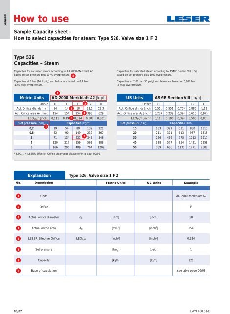
GeneralHow to useSample Capacity sheet –How to select capacities for steam: Type 526, Valve size 1 F 2Type 526Capacities – SteamCapacities for saturated steam according to AD 2000-Merkblatt A2,based on set pressure plus 10 % overpressure.8Capacities at 1 bar (14,5 psig) and below are based on 0,1 bar(1,45 psig) overpressure.Capacities for saturated steam according to ASME Section VIII (UV),based on set pressure plus 10% overpressure.Capacities at 2,07 bar (30 psig) and below are based on 0,207 bar(3 psig) overpressure.Metric Units1AD 2000-Merkblatt A2 [kg/h]Orifice D E F 2 G HAct. Orifice dia. d0 [mm] 14 14 3 18 22,5 28,3Act. Orifice area A 0 [mm 2 ] 154 154 254 4 398 629LEOS/G* ) [inch 2 ] 0,111 0,196 5 0,324 0,506 0,801Set pressure [bar]Capacities [kg/h]0,2619 54 89 139 2210,5 42 90 149 232 3671 71 134 2217345 5462 120 217 359 561 8883 166 296 489 764 1209US Units ASME Section VIII [lb/h]Orifice D E F G HAct. Orifice dia. d0 [inch] 0,551 0,551 0,709 0,886 1,11Act. Orifice area A 0 [inch 2 ] 0,239 0,239 0,394 0,616 0,975LEOS/G* ) [inch 2 ] 0,111 0,196 0,324 0,506 0,801Set pressure [psig]Capacities [lb/h]15 183 321 531 830 131320 211 371 613 957 151530 266 469 775 1212 191740 328 577 954 1491 235950 389 686 1133 1771 2802* ) LEO S/G = LESER Effective Orifice steam/gas please refer to page 00/09Explanation Type 526, Valve size 1 F 2No. Description Metric Units US Units Example1Code AD 2000-Merkblatt A22OrificeF3Actual orifice diameter d 0 [mm] [inch] 184Actual orifice area A 0 [mm 2 ] [inch 2 ] 2545LESER Effective Orifice LEO S/G [inch 2 ] [inch 2 ] 0,3246Set pressure [bar g ] [psig] 17Capacity [kg/h] [lb/h] 2218Base of calculation see table page 00/0800/07 LWN 480.01-E
How to useGeneral8Base of calculationMetric UnitsUS UnitsCodeCapacity calculation according toAD 2000-Merkblatt A2Capacity calculation according toASME Section VIII (UV)MediaSTEAM(saturated steam)StandardconditionsSteam table IAPWS-IF97IAPWS Industrial Formulation forthe Thermodynamic Propertiesof Water and Steam[kg/h]Steam table IAPWS-IF97IAPWS Industrial Formulation forthe Thermodynamic Propertiesof Water and Steam[lb/h]AIRStandardconditions0 °C and 1013 mbar [m n 3 /h] 16 °C (60 °F) [S.C.F.M.]WATERStandardconditions20 °C (68 °F) [10 3 kg/h] 21 °C (70 °F) [US-G.P.M.]All MediaCalculationpressureSet pressure plus 10 % overpressureSet pressure plus 10 % overpressureCalculationpressure forlow set pressureCapacities at 1 bar (14,5 psig)and below are based on 0,1 bar(1,45 psig) overpressure.Capacities at 2,07 bar (30 psig)and below are based on0,207 bar (3 psig) overpressure.ExampleCapacity calculation pressureMetric UnitsUS UnitsSet pressure Capacity calculation pressure Set pressure Capacity calculation pressure10 bar 10 bar + 10% overpressure = 11 bar 145 psig 145 psig + 10% overpressure = 159,5 psig0,5 bar 0,5 bar + 0,1 bar overpressure = 0,6 bar 20 psig 20 psig + 3 psig overpressure = 23 psig5LESER Effective OrificePressure relief devices may be initially sized using theequations shown in <strong>API</strong> RP 520, sections 3.6 through 3.10as appropriate for vapors, gases, liquids, or two phase flow.These equations utilize effective coefficient of discharge (S/G0,975, L 0,650) and effective areas (acc. to <strong>API</strong> Std. 526, FifthEdition, June 2002, table 1) which are independent of anyspecificvalve design. In this way the designer can determine apreliminary pressure relief valve size. By using the LESEREffective Orifice the designer can directly select a LESERsafety relief valve after calculating the oriffice letter. In thiscase, a verification of the sizing with the selected actualorifice and the rated coefficient of discharge is not necessary.LEO S/GLESER Effective Orifice (for steam, gas and vapor) [inch 2 ] refer to page 00/09LEO LLESER Effective Orifice (for liquid) [inch 2 ] refer to page 00/10For further information refer to LESER Engineering HandbookLWN 480.01-E00/08
- Page 1 and 2: APIFlanged Safety Relief ValvesSeri
- Page 3 and 4: ContentsChapter/PageGeneral 00/01Ap
- Page 5 and 6: General InformationGeneralApplicati
- Page 7 and 8: Valve finderHow to find the right A
- Page 9: How to useSelection chartsGeneralTh
- Page 13 and 14: LEOLGeneralThis table is based on t
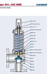
- Page 15 and 16: TypeType 526Type 526Packed lever H4
- Page 17 and 18: Type 526Conventional designItemMate
- Page 19 and 20: Type 526Balanced bellows designMate
- Page 21 and 22: Type 5264 5 6Options Documentation
- Page 23 and 24: Type 526Article numbers - OverviewA
- Page 25 and 26: d 0 = Actual orifice diameterA 0 =
- Page 27 and 28: d 0 = Actual orifice diameterA 0 =
- Page 29 and 30: Type 526WeightsUS UnitsBonnetallLif
- Page 31 and 32: Type 526Orifice DArticle numbers, d
- Page 33 and 34: Type 526Orifice DPressure temperatu
- Page 35 and 36: Type 526Orifice EArticle numbers, d
- Page 37 and 38: Type 526Orifice EPressure temperatu
- Page 39 and 40: Type 526Orifice FArticle numbers, d
- Page 41 and 42: Type 526Orifice FPressure temperatu
- Page 43 and 44: Type 526Orifice GArticle numbers, d
- Page 45 and 46: Type 526Orifice GPressure temperatu
- Page 47 and 48: Type 526Orifice HArticle numbers, d
- Page 49 and 50: Type 526Orifice HPressure temperatu
- Page 51 and 52: Type 526Orifice JArticle numbers, d
- Page 53 and 54: Type 526Orifice JPressure temperatu
- Page 55 and 56: Type 526Orifice KArticle numbers, d
- Page 57 and 58: Type 526Orifice KPressure temperatu
- Page 59 and 60: Type 526Orifice LArticle numbers, d
- Page 61 and 62:
Type 526Orifice LPressure temperatu
- Page 63 and 64:
Type 526Orifice MArticle numbers, d
- Page 65 and 66:
Type 526Orifice MPressure temperatu
- Page 67 and 68:
Type 526Orifice NArticle numbers, d
- Page 69 and 70:
Type 526Orifice NPressure temperatu
- Page 71 and 72:
Type 526Orifice PArticle numbers, d
- Page 73 and 74:
Type 526Orifice PPressure temperatu
- Page 75 and 76:
Type 526Orifice QArticle numbers, d
- Page 77 and 78:
Type 526Orifice QPressure temperatu
- Page 79 and 80:
Type 526Orifice RArticle numbers, d
- Page 81 and 82:
Type 526Orifice RPressure temperatu
- Page 83 and 84:
Type 526Orifice TArticle numbers, d
- Page 85 and 86:
Type 526Orifice TPressure temperatu
- Page 87 and 88:
Type 526Flange facingsIndication St
- Page 89 and 90:
Orifice900 x 300 1500 x 300 2500 x
- Page 91 and 92:
Type 526Spare parts - Disc (Item 7)
- Page 93 and 94:
Type 526Spare parts - Stainless ste
- Page 95 and 96:
Type 526Spare parts - Gasket Body /
- Page 97 and 98:
Type 526Spare parts recommendations
- Page 99 and 100:
Type 526ApprovalsApprovalsOrifice D
- Page 101 and 102:
Type 526Capacities - SteamCapacitie
- Page 103 and 104:
Type 526Capacities - AirCapacities
- Page 105 and 106:
Type 526Capacities - WaterCapacitie
- Page 107 and 108:
Accessoriesand OptionsContentsChapt
- Page 109 and 110:
Accessories and OptionsCaps and lev
- Page 111 and 112:
Accessories and OptionsCaps and lev
- Page 113 and 114:
Accessories and OptionsMetal seat -
- Page 115 and 116:
Accessories and OptionsSoft seal di
- Page 117 and 118:
Accessories and OptionsSoft sealSof
- Page 119 and 120:
Accessories and OptionsBalanced bel
- Page 121 and 122:
Accessories and OptionsLift indicat
- Page 123 and 124:
Accessories and OptionsHeating jack
- Page 125 and 126:
Accessories and OptionsO-ring dampe
- Page 127 and 128:
Fax OrderPlease send your request t


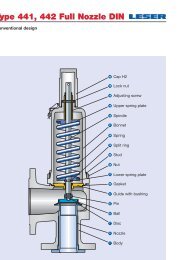
![Stückliste Type 441, 442 DIN [DE] - Leser](https://img.yumpu.com/50352159/1/189x260/stuckliste-type-441-442-din-de-leser.jpg?quality=85)