Type 526DimensionsType 526US UnitsSafety valve dimensions [inch] a b s Hmax.Hmax.withbellowsa b s Hmax.Hmax.withbellowsa b s Hmax.Support brackets [inch] A B C D E A B C D E A B C D EFlange rating class 150 x 150 300L x 150 300 x 150Valve size 1 D 2 1 D 2 1 D 2DEFGHmax.withbellowsd 0 [inch] 0,552 4 1 / 8 4 1 / 2 1 3 / 16 17 5 / 16 18 5 / 16 Please see 1 D 24 1 / 8 4 1 / 2 1 3 / 16 17 5 / 16 18 5 / 16A 0 [inch 2 ] 0,239 5 1 / 8 – Ø 9 / 16 5 7 / 32 5 / 8300 x 1505 1 / 8 – Ø 9 / 16 5 7 / 32 5 / 81 E 2 1 E 2 1 E 2d 0 [inch] 0,552 4 1 / 8 4 1 / 2 1 3 / 16 17 5 / 16 18 5 / 16 Please see 1 E 24 1 / 8 4 1 / 2 1 3 / 16 17 5 / 16 18 5 / 16A 0 [inch 2 ] 0,239 5 1 / 8 – Ø 9 / 16 5 7 / 32 5 / 8300 x 1505 1 / 8 – Ø 9 / 16 5 7 / 32 5 / 81 1 / 2 F 2 1 1 / 2 F 2 1 1 / 2 F 2d 0 [inch] 0,709 4 7 / 8 4 3 / 4 1 1 / 4 21 3 / 32 22 3 / 32 4 7 / 8 4 3 / 4 1 1 / 4 21 3 / 32 22 3 / 32 4 7 / 8 6 1 13 / 32 21 3 / 32 22 3 / 32A 0 [inch 2 ] 0,394 6 3 / 8 – Ø 9 / 16 5 27 / 5 32 / 8 6 3 / 8 – Ø 9 / 16 5 27 / 5 32 / 8 6 3 / 8 – Ø 14 5 27 / 5 32 / 81 1 / 2 G 3 1 1 / 2 G 3 1 1 / 2 G 3d 0 [inch] 0,886 4 7 / 8 4 3 / 4 1 1 / 4 21 3 / 32 22 19 / 32 4 7 / 8 4 3 / 4 1 1 / 4 21 3 / 32 22 19 / 32 4 7 / 8 6 1 13 / 32 21 3 / 32 22 19 / 32A 0 [inch 2 ] 0,616 6 3 / 8 – Ø 9 / 16 5 27 / 32 5 / 8 6 3 / 8 – Ø 9 / 16 5 27 / 32 5 / 8 6 3 / 8 – Ø 9 / 16 5 27 / 32 5 / 8Flange rating class 150 x 150 300L x 150 300 x 150Valve size 1 1 / 2 H 3 1 1 / 2 H 3 2 H 3HJKd 0 [inch] 1,11 5 1 / 8 4 7 / 8 1 1 / 2 21 11 / 32 22 27 / 32 5 1 / 8 4 7 / 8 1 1 / 2 21 11 / 32 22 27 / 32 5 1 / 8 4 7 / 8 1 11 / 16 26 7 / 32 27 1 / 4A 0 [inch 2 ] 0,98 6 3 / 8 – Ø 9 / 16 6 3 / 32 5 / 8 6 3 / 8 – Ø 9 / 16 6 3 / 32 5 / 8 7 1 / 4 4 11 / 32 Ø 9 / 16 6 31 / 32 5 / 82 J 3 2 J 3 2 J 3d 0 [inch] 1,42 5 3 / 8 4 7 / 8 1 15 / 16 26 1 / 2 28 7 / 16 5 3 / 8 4 7 / 8 1 15 / 16 26 1 / 2 28 7 / 16 7 1 / 4 7 1 / 8 1 15 / 16 30 15 / 16 32 7 / 16A 0 [inch 2 ] 1,58 7 1 / 4 4 11 / 32 Ø 9 / 16 7 1 / 4 5 / 8 7 1 / 4 4 11 / 32 Ø 9 / 16 7 1 / 4 5 / 8 9 3 / 8 5 1 / 2 Ø 23 / 32 9 7 / 32 31 / 323 K 4 3 K 4 3 K 4WCB, LCB, d 0 [inch] 1,69 6 1 / 8 6 3 / 8 1 15 / 16 29 27 / 32 23 11 / 32 Please see 3 K 46 1 / 8 6 3 / 8 1 15 / 16 29 27 / 32 31 11 / 32CF8M (WC6) A 0 [inch 2 ] 2,25 9 3 / 8 5 1 / 2 Ø 23 / 32 8 3 / 31 32 / 32300 x 1509 3 / 8 5 1 / 2 Ø 23 / 32 8 3 / 31 32 / 32WC6Flange rating class 150 x 150 300L x 150 300 x 150Valve size 3 L 4 3 L 4 4 L 6LMNPQRTd 0 [inch] 2,11 6 1 / 8 6 1 / 2 1 15 / 16 23 27 / 32 31 11 / 12 6 1 / 8 6 1 / 2 1 15 / 16 29 27 / 32 31 11 / 12 7 1 / 6 7 1 / 8 1 15 / 16 33 19 / 32 34 7 / 8A 0 [inch 2 ] 3,48 9 3 / 8 5 1 / 2 Ø 23 / 32 8 3 / 32 31 / 32 9 3 / 8 5 1 / 2 Ø 23 / 32 8 3 / 32 31 / 32 10 15 / 16 6 5 / 16 Ø 23 / 32 10 5 / 16 31 / 324 M 6 4 M 6 4 M 6d 0 [inch] 2,37 7 7 1 / 4 1 7 / 8 33 17 / 32 34 27 / 32 Please see 4 M 67 7 1 / 4 1 7 / 8 33 17 / 32 34 27 / 32A 0 [inch 2 ] 4,43 10 15 / 16 6 5 / 16 Ø 23 / 32 10 1 / 4 31 / 32300 x 15010 15 / 16 6 5 / 16 Ø 23 / 32 10 1 / 4 31 / 324 N 6 4 N 6 4 N 6d 0 [inch] 2,60 7 3 / 4 8 1 / 4 1 7 / 8 34 9 / 32 35 19 / 32 Please see 4 N 67 3 / 4 8 1 / 4 1 7 / 8 34 9 / 32 35 19 / 32A 0 [inch 2 ] 5,30 10 15 / 16 6 5 / 16 Ø 23 / 32 11 31 / 32300 x 15010 15 / 16 6 5 / 16 Ø 23 / 32 11 31 / 324 P 6 4 P 6 4 P 6d 0 [inch] 3,15 7 1 / 8 9 1 7 / 8 33 31 / 32 34 31 / 32 7 1 / 8 9 1 7 / 8 33 31 / 32 34 31 / 32 8 7 / 8 10 2 7 / 16 42 1 / 2 44 13 / 16A 0 [inch 2 ] 7,79 10 15 / 16 6 5 / 16 Ø 23 / 32 10 5 / 16 31 / 32 10 15 / 16 6 5 / 16 Ø 23 / 32 10 5 / 16 31 / 32 14 9 / 16 8 9 / 32 Ø 23 / 32 12 1 / 16 31 / 326 Q 8 6 Q 8 6 Q 8d 0 [inch] 4,15 9 7 / 16 9 1 / 2 2 11 / 16 44 1 / 8 47 1 / 4 Please see 6 Q 89 7 / 16 9 1 / 2 2 11 / 16 44 1 / 8 47 1 / 4A 0 [inch 2 ] 13,55 14 9 / 16 8 9 / 32 Ø 23 / 32 13 5 / 8 31 / 32300 x 15014 9 / 16 8 9 / 32 Ø 23 / 32 13 5 / 8 31 / 326 R 8 6 R 8 6 R 10d 0 [inch] 4,98 9 7 / 16 9 1 / 2 2 11 / 16 44 1 / 8 47 1 / 4 9 7 / 16 9 1 / 2 2 11 / 16 41 5 / 8 44 3 / 4 9 7 / 16 10 1 / 2 2 11 / 16 56 1 / 8 56 1 / 8A 0 [inch 2 ] 19,84 14 9 / 16 8 9 / 32 Ø 23 / 32 13 5 / 8 31 / 32 14 9 / 16 8 9 / 32 Ø 23 / 32 13 5 / 8 31 / 32 18 1 / 2 5 29 / 32 Ø 23 / 32 18 1 / 8 31 / 328 T 10 8 T 10 8 T 10d 0 [inch] 6,36 10 7 / 8 11 2 7 / 16 57 9 / 16 57 9 / 16 Please see 8 T 10 10 7 / 8 11 2 7 / 16 57 9 / 16 57 9 / 16A 0 [inch 2 ] 31,75 18 1 / 2 5 29 / 32 Ø 23 / 32 19 9 / 16 31 / 32300 x 15018 1 / 2 5 29 / 32 Ø 23 / 32 19 9 / 16 31 / 3201/12 LWN 480.01-E
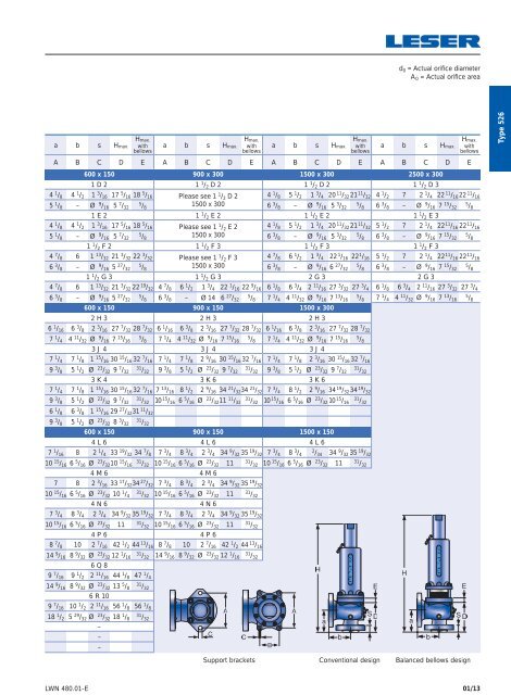
d 0 = Actual orifice diameterA 0 = Actual orifice areaa b s Hmax.Hmax.withbellowsa b s Hmax.Hmax.withbellowsa b s Hmax.Hmax.withbellowsa b s Hmax.A B C D E A B C D E A B C D E A B C D E600 x 150 900 x 300 1500 x 300 2500 x 3001 D 2 1 1 / 2 D 2 1 1 / 2 D 2 1 1 / 2 D 3Hmax.withbellows4 1 / 8 4 1 / 2 1 3 / 16 17 5 / 16 18 5 / 16 Please see 1 1 / 2 D 2 4 1 / 8 5 1 / 2 1 3 / 4 20 11 / 32 21 11 / 32 4 1 / 2 7 2 1 / 4 22 11 / 16 22 11 / 165 1 / 8 – Ø 9 / 16 5 7 / 32 5 / 81500 x 3006 3 / 8 – Ø 9 / 16 5 3 / 32 5 / 8 6 3 / 8 – Ø 9 / 16 7 15 / 32 5 / 81 E 2 1 1 / 2 E 2 1 1 / 2 E 2 1 1 / 2 E 34 1 / 8 4 1 / 2 1 3 / 16 17 5 / 16 18 5 / 16 Please see 1 1 / 2 E 2 4 1 / 8 5 1 / 2 1 3 / 4 20 11 / 32 21 11 / 32 5 1 / 2 7 2 1 / 4 22 11 / 16 22 11 / 165 1 / 8 – Ø 9 / 16 5 7 / 32 5 / 81500 x 3006 3 / 8 – Ø 9 / 16 5 3 / 32 5 / 8 6 3 / 8 – Ø 9 / 16 7 15 / 32 5 / 81 1 / 2 F 2 1 1 / 2 F 3 1 1 / 2 F 3 1 1 / 2 F 34 7 / 8 6 1 13 / 32 21 3 / 32 22 3 / 32 Please see 1 1 / 2 F 3 4 7 / 8 6 1 / 2 1 3 / 4 22 1 / 16 22 1 / 16 5 1 / 2 7 2 1 / 4 22 11 / 16 22 11 / 166 3 / 8 – Ø 9 / 16 5 27 / 32 5 / 81500 x 3006 3 / 8 – Ø 9 / 16 6 27 / 32 5 / 8 6 3 / 8 – Ø 9 / 16 7 15 / 32 5 / 81 1 / 2 G 3 1 1 / 2 G 3 2 G 3 2 G 3Type 5264 7 / 8 6 1 13 / 32 21 3 / 32 22 19 / 32 4 7 / 8 6 1 / 2 1 3 / 4 22 1 / 16 22 9 / 16 6 1 / 8 6 3 / 4 2 11 / 16 27 3 / 32 27 3 / 4 6 1 / 8 6 3 / 4 2 11 / 16 27 3 / 32 27 3 / 46 3 / 8 – Ø 9 / 16 5 27 / 32 5 / 8 6 3 / 8 – Ø 14 6 27 / 32 5 / 8 7 1 / 4 4 11 / 32 Ø 9 / 16 7 13 / 16 5 / 8 7 1 / 4 4 11 / 32 Ø 9 / 16 7 13 / 16 5 / 8600 x 150 900 x 150 1500 x 3002 H 3 2 H 3 2 H 36 1 / 16 6 3 / 8 2 3 / 16 27 7 / 32 28 7 / 32 6 1 / 16 6 3 / 8 2 3 / 16 27 7 / 32 28 7 / 32 6 1 / 16 6 3 / 8 2 3 / 16 27 7 / 32 28 7 / 327 1 / 4 4 11 / 32 Ø 9 / 16 7 15 / 16 5 / 8 7 1 / 4 4 11 / 32 Ø 9 / 16 7 15 / 16 5 / 8 7 1 / 4 4 11 / 32 Ø 9 / 16 7 15 / 16 5 / 83 J 4 3 J 4 3 J 47 1 / 4 7 1 / 8 1 15 / 16 30 15 / 16 32 7 / 16 7 1 / 4 7 1 / 8 2 9 / 16 30 15 / 16 32 7 / 16 7 1 / 4 7 1 / 8 2 3 / 16 30 15 / 16 32 7 / 169 3 / 8 5 1 / 2 Ø 23 / 32 9 7 / 32 31 / 32 9 3 / 8 5 1 / 2 Ø 23 / 32 9 7 / 32 31 / 32 9 3 / 8 5 1 / 2 Ø 23 / 32 9 7 / 32 31 / 323 K 4 3 K 6 3 K 67 1 / 4 7 1 / 8 1 15 / 16 30 15 / 16 32 7 / 16 7 13 / 16 8 1 / 2 2 9 / 16 34 21 / 32 34 21 / 32 7 3 / 4 8 1 / 2 2 9 / 16 34 19 / 32 34 19 / 329 3 / 8 5 1 / 2 Ø 23 / 32 9 7 / 32 31 / 32 10 15 / 16 6 5 / 16 Ø 23 / 32 11 11 / 32 31 / 32 10 15 / 16 6 5 / 16 Ø 23 / 32 10 15 / 16 31 / 326 1 / 8 6 3 / 8 1 15 / 16 29 27 / 32 31 11 / 329 3 / 8 5 1 / 2 Ø 23 / 32 8 3 / 32 31 / 32600 x 150 900 x 150 1500 x 1504 L 6 4 L 6 4 L 67 1 / 16 8 2 1 / 4 33 19 / 32 34 7 / 8 7 3 / 4 8 3 / 4 2 3 / 4 34 9 / 32 35 19 / 32 7 3 / 4 8 3 / 4 2 / 34 34 9 / 32 35 19 / 3210 15 / 16 6 5 / 16 Ø 23 / 32 10 15 / 16 31 / 32 10 15 / 16 6 5 / 16 Ø 23 / 32 11 31 / 32 10 15 / 16 6 5 / 16 Ø 23 / 32 11 31 / 324 M 6 4 M 67 8 2 3 / 16 33 17 / 32 34 27 / 32 7 3 / 4 8 3 / 4 2 3 / 4 34 9 / 32 35 19 / 3210 15 / 16 6 5 / 16 Ø 23 / 32 10 1 / 4 31 / 32 10 15 / 16 6 5 / 16 Ø 23 / 32 11 31 / 324 N 6 4 N 67 3 / 4 8 3 / 4 2 3 / 4 34 9 / 32 35 19 / 32 7 3 / 4 8 3 / 4 2 3 / 4 34 9 / 32 35 19 / 3210 15 / 16 6 5 / 16 Ø 23 / 32 11 31 / 32 10 15 / 16 6 5 / 16 Ø 23 / 32 11 31 / 324 P 6 4 P 68 7 / 8 10 2 7 / 16 42 1 / 2 44 13 / 16 8 7 / 8 10 2 7 / 16 42 1 / 2 44 13 / 1614 9 / 16 8 9 / 32 Ø 23 / 32 12 1 / 16 31 / 32 14 9 / 16 8 9 / 32 Ø 23 / 32 12 1 / 16 31 / 326 Q 89 7 / 16 9 1 / 2 2 11 / 16 44 1 / 8 47 1 / 414 9 / 16 8 9 / 32 Ø 23 / 32 13 5 / 8 31 / 326 R 109 7 / 16 10 1 / 2 2 11 / 16 56 1 / 8 56 1 / 818 1 / 2 5 29 / 32 Ø 23 / 32 18 1 / 8 31 / 32–––Support bracketsConventional designBalanced bellows designLWN 480.01-E01/13
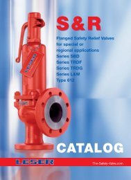
- Page 1 and 2: APIFlanged Safety Relief ValvesSeri
- Page 3 and 4: ContentsChapter/PageGeneral 00/01Ap
- Page 5 and 6: General InformationGeneralApplicati
- Page 7 and 8: Valve finderHow to find the right A
- Page 9 and 10: How to useSelection chartsGeneralTh
- Page 11 and 12: How to useGeneral8Base of calculati
- Page 13 and 14: LEOLGeneralThis table is based on t
- Page 15 and 16: TypeType 526Type 526Packed lever H4
- Page 17 and 18: Type 526Conventional designItemMate
- Page 19 and 20: Type 526Balanced bellows designMate
- Page 21 and 22: Type 5264 5 6Options Documentation
- Page 23 and 24: Type 526Article numbers - OverviewA
- Page 25: d 0 = Actual orifice diameterA 0 =
- Page 29 and 30: Type 526WeightsUS UnitsBonnetallLif
- Page 31 and 32: Type 526Orifice DArticle numbers, d
- Page 33 and 34: Type 526Orifice DPressure temperatu
- Page 35 and 36: Type 526Orifice EArticle numbers, d
- Page 37 and 38: Type 526Orifice EPressure temperatu
- Page 39 and 40: Type 526Orifice FArticle numbers, d
- Page 41 and 42: Type 526Orifice FPressure temperatu
- Page 43 and 44: Type 526Orifice GArticle numbers, d
- Page 45 and 46: Type 526Orifice GPressure temperatu
- Page 47 and 48: Type 526Orifice HArticle numbers, d
- Page 49 and 50: Type 526Orifice HPressure temperatu
- Page 51 and 52: Type 526Orifice JArticle numbers, d
- Page 53 and 54: Type 526Orifice JPressure temperatu
- Page 55 and 56: Type 526Orifice KArticle numbers, d
- Page 57 and 58: Type 526Orifice KPressure temperatu
- Page 59 and 60: Type 526Orifice LArticle numbers, d
- Page 61 and 62: Type 526Orifice LPressure temperatu
- Page 63 and 64: Type 526Orifice MArticle numbers, d
- Page 65 and 66: Type 526Orifice MPressure temperatu
- Page 67 and 68: Type 526Orifice NArticle numbers, d
- Page 69 and 70: Type 526Orifice NPressure temperatu
- Page 71 and 72: Type 526Orifice PArticle numbers, d
- Page 73 and 74: Type 526Orifice PPressure temperatu
- Page 75 and 76: Type 526Orifice QArticle numbers, d
- Page 77 and 78:
Type 526Orifice QPressure temperatu
- Page 79 and 80:
Type 526Orifice RArticle numbers, d
- Page 81 and 82:
Type 526Orifice RPressure temperatu
- Page 83 and 84:
Type 526Orifice TArticle numbers, d
- Page 85 and 86:
Type 526Orifice TPressure temperatu
- Page 87 and 88:
Type 526Flange facingsIndication St
- Page 89 and 90:
Orifice900 x 300 1500 x 300 2500 x
- Page 91 and 92:
Type 526Spare parts - Disc (Item 7)
- Page 93 and 94:
Type 526Spare parts - Stainless ste
- Page 95 and 96:
Type 526Spare parts - Gasket Body /
- Page 97 and 98:
Type 526Spare parts recommendations
- Page 99 and 100:
Type 526ApprovalsApprovalsOrifice D
- Page 101 and 102:
Type 526Capacities - SteamCapacitie
- Page 103 and 104:
Type 526Capacities - AirCapacities
- Page 105 and 106:
Type 526Capacities - WaterCapacitie
- Page 107 and 108:
Accessoriesand OptionsContentsChapt
- Page 109 and 110:
Accessories and OptionsCaps and lev
- Page 111 and 112:
Accessories and OptionsCaps and lev
- Page 113 and 114:
Accessories and OptionsMetal seat -
- Page 115 and 116:
Accessories and OptionsSoft seal di
- Page 117 and 118:
Accessories and OptionsSoft sealSof
- Page 119 and 120:
Accessories and OptionsBalanced bel
- Page 121 and 122:
Accessories and OptionsLift indicat
- Page 123 and 124:
Accessories and OptionsHeating jack
- Page 125 and 126:
Accessories and OptionsO-ring dampe
- Page 127 and 128:
Fax OrderPlease send your request t


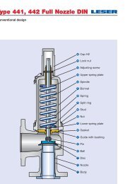
![Stückliste Type 441, 442 DIN [DE] - Leser](https://img.yumpu.com/50352159/1/189x260/stuckliste-type-441-442-din-de-leser.jpg?quality=85)