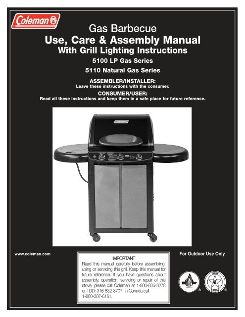
9990-132 - 5100 Series - Gas Barbcue - Coleman
9990-132 - 5100 Series - Gas Barbcue - Coleman
9990-132 - 5100 Series - Gas Barbcue - Coleman
- No tags were found...

You also want an ePaper? Increase the reach of your titles
YUMPU automatically turns print PDFs into web optimized ePapers that Google loves.
Electrical AttachmentsWhen using an electric attachment with grill, follow specificationand warning statements accompanying the attachment.IMPORTANT: If using an external electrical source, the installedappliance must be electrically grounded according to local codesor, in the absence of local codes, with the National ElectricalCode, ANSI/NFPA 70 or the Canadian Electrical Code CSAC22.1.WARNINGElectrical Grounding instructions: An applianceequipped with a three-prong (grounding) plug is foryour protection against shock hazard and must beplugged directly into a properly grounded three-prongreceptacle. DO NOT remove grounding prong from athree-prong plug.Longer detachable power-supply cords or extension cords mustbe used with care. The marked electrical rating of the cord set orextension cord must be at least as great as the electrical rating ofthe appliance. If the appliance is of the grounded type, the extensioncord should be a grounding-type 3-wire cord. Use outdoorextension cords with a surface marked with suffix letters “W-A”and with a tag stating “Suitable for Use with Outdoor Appliances”.Keep the connection to an extension cord away from water andoff the ground. Arrange the cord so that it will not drape over thecountertop or tabletop where it can be pulled on by children ortripped over unintentionally.Never clean any electrical product with water or cleaning fluids.Store electrical products indoors and out of reach of childrenwhen not in use. DO NOT allow cord to touch any hot surfaceswhich could melt insulation.LP Fuel Connections Other ThanPortable L.P. CylindersCAUTION• This section applies to L.P. <strong>Gas</strong> (Propane) Grills and onlywhere propane gas is to be piped to the grill.• Natural gas can be used only with grills which have beenequipped for use with natural gas.If the appliance is for connection to other than an L.P. cylinder(consult the Assembly Instructions) the gas connections must bemade by a qualified installer or a licensed plumber. The gas supplyline must not be installed by the consumer.The maximum inlet supply pressure is 13.0" w.c. for propane gas.The specified supply pressure is 11.0" w.c. for propane gas.THE PIPING SYSTEM MUST BE INSTALLED IN ACCORDANCEWITH NATIONAL FUEL GAS CODE IN THE USA, INCLUDING:1. The appliance and its individual shut-off valve must be disconnectedfrom the gas supply piping system during anypressure testing of that system at test pressures in excessof 1/2 psi (3.5 kPa).2. The appliance must be isolated from the gas supply pipingsystem by closing its individual manual shut-off valve duringany pressure testing of the gas supply piping system at testpressures equal to or less than 1/2 psi (3.5 kPa).Natural <strong>Gas</strong> ConnectionsPortable L.P. <strong>Gas</strong> Barbecue CylindersLiquefied Petroleum gas (abbreviated L.P. gas or propane), ishighly flammable. It becomes liquid when stored under high pressureinside a cylinder and vaporizes when released. L.P. gas isheavier than air and tends to collect in low areas. It is importantthat there are no leaking connections on your gas grill that couldcause a fire or explosion (see “LEAK TESTING”, Pg. 26).Portable LP gas grills require a fuel delivery system which iscomprised of a valve [A], a hose [B], a regulator [C] with vent hole[G], an L.P. gas supply cylinder [D], a Type 1 coupling nut [E] anda Type 1 cylinder valve [F]. (Fig. 10). Illustration in Fig. 10 is fordescription purposes only. The valve assembly for this grill is of adifferent configuration.EBCWARNINGYour new barbecue grill is equipped with a Type 1 couplingnut [E]. DO NOT attempt to connect to any other L.P. cylindernot equipped with a mating Type 1 cylinder valve [F]. This grillis not to be used with any other cylinder connection device.10WARNING• <strong>Gas</strong> supply system must be installed in accordance with the U.S.National Fuel <strong>Gas</strong> Code.• This appliance and its individual shut off valve must be disconnectedfrom the gas supply piping system during any system pressure test inexcess of 1/2 PSI (3.5 KPA).• Use a system manual shut off valve to shut off the gas supply to thisgas appliance before continuing with installation procedures.The maximum inlet supply pressure is 10.5" w.c. for natural gas.The specified supply pressure is 7.0" w.c. for natural gas.WARNINGA liquid propane tank, not connected for use with this gas barbecue,shall not be stored in the vicinity of this or any other appliance.Installation and provision for combustion and ventilation airmust conform with the National Fuel <strong>Gas</strong> Code, ANSI Z223.1,or CAN/CGA-B149.1, Natural <strong>Gas</strong> Installation Code, orCAN/CGA-B149.2, Propane Installation Code.Connections must comply with local requirements and are thesole responsibility of the person performing the work. A certifiedplumber must make connection to gas source.AFD4G
DANGER• DO NOT insert any foreign objects into the valve outlet.You may damage the valve. A damaged valve can causea leak, which could result in explosion, fire, severe personalinjury or death.WARNING• Cylinders must be stored outdoors out of the reach ofchildren and must not be stored in a building, garage orany other enclosed area. (Fig. 11)Cylinder Specifications• Any L.P. gas supply cylinder used with this grill must beapproximately 12 inches diameter and 18 inches high. Themaximum fuel capacity is 80% and is approximately 20 poundsof propane.• The maximum weight of a properly filled cylinder will beapproximately 38 pounds (47.7 lbs. nominal water capacity).• The L.P. cylinder must have a shut-off valve terminating in aType 1 L.P. gas cylinder valve outlet (see item [F], Fig. 10,pg. 4).11L.P. <strong>Gas</strong> CylinderL.P. <strong>Gas</strong> Cylinder cont.CAUTIONHave the gas dealer weigh cylinder after filling to ensure thatthe cylinder is not overfilled.Hose and RegulatorThe Type 1 connection system has the following features:1.The system will not allow gas to flow until a positive connectionhas been made.NOTE: The cylinder control valve must be turned off before anyconnection is made or removed.2.The system has a thermal element that will shut off the flow ofgas in the event of a fire.3.The system has a flow limiting device which, when activated, willlimit the flow of gas to 10 cubic feet per hour.4.NEVER use grill without leak testing this connection.WARNING• DO NOT attempt to adjust the regulator as this couldcreate a situation causing personal injury or propertydamage.The pressure regulator and hose assembly with the Type 1 fittingsupplied with the appliance must be used. Do not use anotherhose and regulator assembly other than the one supplied with thegrill or a <strong>Coleman</strong> replacement pressure regulator assembly. Thepressure regulator and hose assembly provided is factory set atan outlet pressure of 11 inches water column (1/2 psi).• Keep the small vent hole in the regulator clean of dirt and debris(see item [G], Fig. 10, pg. 4).• Consult your L.P. gas dealer if you think the regulator is notworking properly.• A Type 1 compatible cylinder with a Type 1 cylinder valve hasa back-check valve which does not permit gas flow, until a positiveseal has been obtained.• The cylinder must be arranged for vapor withdrawal. It mustalso include a collar to protect the cylinder valve. A safety reliefdevice having direct communication with the vapor space ofcylinder must be provided. This will expel high pressure gas ifthe cylinder is overfilled or overheated which could result in fireor explosion.• All L.P. gas cylinders used with this appliance shall be constructedand marked in accordance with the specifications forL.P. gas cylinders of the U. S. Department of Transportation(DOT) or the National Standard of Canada, CAN/CSA-B339,Cylinders, Spheres and Tubes for Transportation of DangerousGoods; and Commission, as applicable; and shall be providedwith a listed overfilling prevention device.• Read labels on the L.P. <strong>Gas</strong> Supply Cylinder.• New cylinders are always shipped empty for safety.• Allow only qualified L.P. gas dealers to fill or repair your L.P.gas supply cylinder.• Inform the gas dealer if it is a new or used cylinder to be filled.• Caution the gas dealer not to overfill cylinder.• After filling, have the gas dealer check for leaks and to see thatthe relief valve remains free to function.WARNINGDuring assembly of grill and when attaching or replacingthe L.P. gas cylinder, insure that the gas supply hose is freeof kinks and/or damage and is at least 3" away from hot surfacessuch as the grill housing.Transporting the Cylinder• Transport only one cylinder at a time.• Transport cylinder in an upright and secure manner with a controlvalve turned off and the cap in place.• DO NOT transport cylinder in passenger compartment, unlessyou have an open window ventilation.• DO NOT leave cylinder in direct sunlight or in a high heat areasuch as a closed car trunk. High heat areas could cause the reliefvalve to vent gas.• Use a cylinder cap on cylinder valve outlet during transport andwhen the cylinder is not connected to grill.• Keep cylinder valve closed when not in use.• Take the cylinder directly home after it has been filled.5
Transporting the Cylinder cont.WARNINGHandle a full cylinder with care. <strong>Gas</strong> is under high pressure.Filling and Purging Type 1L.P. <strong>Gas</strong> Cylinders cont.13CGA-510 POLDANGER• NEVER store a spare L.P. gas supply cylinder under thegrill body or inside grill enclosure or in the vicinity of anyheat producing appliance. (Fig. 12)• NEVER fill the cylinder beyond 80% full.Failure to follow this information exactly could result in anexplosion and/or fire causing death or serious injury.12Purging and Evacuating Devices for L.P.<strong>Gas</strong> Cylinders with Type 1 Cylinder ValvesCAUTIONAfter purging or filling an L.P. <strong>Gas</strong> cylinder, DO NOT insert aPOL plug into the valve outlet. Insertion of the plug will preventthe back-check from closing. Use ONLY the providedcap and strap attached to the outlet. Close the cylinder valveknob before returning the cylinder to the customer.For proper purging procedures refer to:In the US: Safety Bulletin NPGA# 133, “Purging L.P. <strong>Gas</strong>Cylinders”, and Safety Bulletin NPGA #130, “RecommendedProcedures for Filling Cylinders”.Filling and Purging Type 1L.P. <strong>Gas</strong> CylindersTake these instructions to the L.P. gas dealer.DANGERPurging and filling of L.P. <strong>Gas</strong> cylinders must be performedby personnel who have been thoroughly trained in acceptedL.P. <strong>Gas</strong> industry procedures. Failure to follow this instructionmay result in explosion, fire, serious personal injury, ordeath.A. Hose end valve with a bleed port (Fig. 13):Purging can be accomplished using a hose end valvecontaining a bleed port which also allows for evacuation withoutthe use of an adapter.B. Hose end valve without a bleed port:When a hose end valve does not have a bleed port, a separatedevice must be used for evacuation.C. Purging using a Type 1 connection (Fig. 14):L.P. <strong>Gas</strong> cylinder evacuation can be accomplished during eachpurging by using a Type 1 connection. The Type 1 valve outlethas an external 1 5/16" ACME right-hand thread which willaccept this connection.14TYPE 16• When using cylinder exchange: If your grill is equipped with aType 1 cylinder, be sure the exchanged cylinder is a Type 1cylinder, as a 510 POL cylinder will not fit Type 1 regulator.• This tank is easily filled with a standard CGA 510 POL fillingconnection. (Fig. 13)• New cylinders must be purged before filling. Tell your L.P. <strong>Gas</strong>dealer if your cylinder is new and has not been previously filled.The L.P. <strong>Gas</strong> cylinder has a Type 1 cylinder valve with a backcheckmodule in its outlet which will not permit gas to flow untilan evacuation device is installed. To purge the L.P. <strong>Gas</strong> cylinder, the back-check module must be opened with an evacuationdevice.
NOTE: Use a large piece of cardboard or a groundcloth to protect the painted finish on the grill.Step1Hardware shown actual size1-ARight Panel(TN)M6 x 15mm Screw(10) Qty.TNLeft PanelBase1-A. Arrange the two panels and the base on the ground as shown. LOOSELY assemble the Right Panel and the Left Panel to the Grill Baseusing one screw (TN) in each top corner.1-BTN (x2)1-CLeftPanelFlangeTN (x2)TN (x2)1-B. LOOSELY assemble two fasteners (TN) into each bottomcorner from the outside.1-C. LOOSELY assemble two fasteners (TN) through the LeftPanel Flange into the Base (as illustrated). Repeat Step 1-C on the Right Panel Flange.8
Step2Carefully turn the assemblyup-side-down to performStep 2. This will give easyaccess to assemble theparts in Step 2.Hardware shown actual size2-C(TN)M6 x 15mm Screw(8) Qty.TN (x2)2-A Base (up-side-down)2-A. Carefully turn the grill Up-Side-Down.2-A. Carefully turn the grill Up-Side-Down.2-BSee Detail 2-C2-DLockingCastersNon-LockingCastersTN (x4)FrontTN (x4)2-B. Assemble eight additional screws (TN) to fasten the SidePanels to the base Base. Tighten all fasteners.2-D. Fasten Casters tight against the Caster Brackets.Back9
Fasten the Firebox to theGrill Cart.Hardware shown actual sizeStep10(TN)M6 x 15mm Screw(6) Qty.(DY)M6 Flat Washer(4) Qty.(UO)M6 Locking Hex Nut(4) Qty.10-ATN (x3)DY (x2)UO (x2)10-A. LOOSELY fasten the right side of the Firebox to the Grill Cart with threeScrews (TN), two Flat Washers (DY) and two Locking Hex Nuts (UO). NOTE: You will tighten these screws LATER (after Step 10-B), after the leftside of the Firebox is attached to the Grill Cart (this helps with alignment).10-BDY (x2)UO (x2)TN (x3)10-B. Fasten the left side of the Firebox to the Grill Cart with three Screws(TN), two Flat Washers (DY) and two Locking Hex Nuts (UO). Tighten all fasteners.15
Fasten the Rear Trim Plateto the Grill Cart.Step11Hardware shown actual size(VP)Self Tapping Screw(2) Qty.11-AFIREBOXREARTRIMPLATE11-BREARTRIMPLATEVP (x2)11-A. Fasten theRear TrimPlate to theFirebox withtwo Screws(VP). Tighten allfasteners.VP11-B. View showing Rear Trim Plate properly installed.16
Step12Fasten both Left and RightDoors to the Grill Cart.Attach the Tool Hook to theRight Door.Hardware shown actual size(XR)M5 x 15mm Flat Head Screw(8) Qty.12-A12-CTOOL HOOKXR (x4)LEFT DOORRIGHT DOOR12-C. Fasten the Right Door to the Grill Cart with four FlatHead Screws (XR). Repeat Step 12-C to attach the Left Door. Tighten all fasteners.5-BTOOL HOOK12-B. Squeeze the Tool Hook to slip into the mountingbrackets.17
Step13Install three Heat Tents.Install three CookingGrates.Install the Warming Rack.13-BHeatTents13-AWarmingRackCookingGrates13-B. Install three Heat Tents over the Burners. The Heat Tents are located using the alignment pins.13-CStandardGratePowerGrateStandardGrateHeatTentsBurners13-C. Install three Cooking Grates, flat side downward. Locate the Power Grate in the center position.13-DWarmingRack1813-D. Place the Warming Rack in the back of the Firebox. Align four posts downward into four holes.
Install the Side BurnerValve.Hardware shown actual sizeStep14(WQ)M4 X 10mm Screw(2) Qty.14-A14-BSideBurnerValveLargeHole14-A. Route the Side Burner Valve through the Large Hole inthe Left Panel.14-CWQ (x2)ViewfromAbove14-DSideBurnerValve14-EView From Back of Grill14-C. Attach the Side Burner Valve with two Screws (WQ).ViewfromBelow19
Step15Assemble the Side Burnerto the Left Side Table.Assemble the Electrode tothe Side Burner.Hardware shown actual size(ZT)Hair Pin(1) Qty.(Attached to Burner)(WQ)M4 X 10mm Screw(1) Qty.(YS)M4 Hex Nut(1) Qty.15-A15-CZTYSWQElectrode15-A. Slip the Burner Tube through the Left Side Table.15-C. Lock the Side Burner in place with one hairpin (SS). Install electrode as shown with one screw (WQ) and onehex nut (YS).15-BBurnerValveBurnerTube15-DCaution: Assemble thewires BELOW the burnertubes!15-B. Align Burner Tube with Burner Valve. NOTE: Make sure Burner Valve is inserted into BurnerTube.15-D. View showing Side Burner properly installed.20
16-AStep169-Volt Battery Assemble the ElectrodeWires and the Battery to theElectrode Module.Note: The fuel hoses are notshown in this step, forsimplicity.Top Burner WiresElectrode Module16-A. Slip the Top Burner Wires through thelarge hole in the Top Panel. Slip the Side Burner Wire through thelarge hole in the Left Panel. Assemble the 9-Volt Battery to theElectrode Module.Note: The polarity is marked on the ElectrodeModule.Side Burner Wire16-BElectrode Module9-Volt BatteryTEST THE IGNITER:A SPARK SHOULD APPEAR ATELECTRODE TIP.IF THE SPARK DOES NOTAPPEAR:-CHECK THE WIRECONNECTIONS TO THEMODULE.-CHECK PROPERASSEMBLY OF FRESH9-VOLT BATTERY.Igniter Button Wires(Note: Large Tabs)Side BurnerElectrode Wire21
Step17Install Side Burner Knoband Side Burner Grate ontothe Left Side Burner.Step18 Assemble the Grease CupSupport to the Grease Pan.Note: The Grease Pan is shownup-side-down during this step.Hardware shown actual size(VP)Self Tapping Screw(2) Qty.18-A17-ASideBurnerGrateSideBurnerKnobGreaseCupSupportVP (x2)Note: SmallSurfacehere.GreasePan17-A. Place the Side Burner Knob on the valve stem. Place the Side Burner Grate on the Left Side Burner.Align the pins downward into the alignment holes.Note: Lipis up.2218-A. Attach the Grease Cup Support to the Grease Pan withtwo self-tapping screws (VP).
Step19Install the Grease Pan.Install the Grease Cup.19-AGrease PanRear Support19-A. Slide the Grease Pan Assembly into the back of the grill. Tilt the pan slightly upward until the Grease Cup Supportclears the Rear Support.19-BGrease Cup19-B. Place the Grease Cup into the Grease Cup Support.Note: Pull the Grease Pan outward slightly for easier accesswhen installing/removing the Grease Cup. After the Grease Cup is installed, push the Grease Panforward until it contacts the location stops.23
NOTE: Step 20 applies to you only if your grill is set up from the factory to use LP GAS. If your grill is set up from the factory touse NATURAL GAS, skip to Step 21.Step20Attach an LP Cylinder to theGrill.20-C20-ALP CylinderCylinder SupportType 1 NippleFuel Valve Outlet20-A. Set LP Cylinder in the Cylinder Support with the outletvalve facing toward the front of the grill.20-C. Insert the TYPE 1 Nipple of the regulator into the cylinder’sFuel Valve Outlet as shown. Turn the regulatorhand wheel clockwise to tighten. No tools are needed.The hand wheel will come to a complete stop when theconnection is secure, and gas will not flow until a positiveseal is achieved.20-BIMPORTANT!TO ENSURE PROPER GAS FLOW, BURNERCONTROL VALVES MUST BE “OFF” BEFOREOPENING THE GAS CYLINDER VALVE.Cylinder Hold-Down Bolt20-B. Tighten the Cylinder Hold-Down Bolt against the bottomcylinder collar.WARNING: During assembly ofgrill and when attaching or replacing theL.P. gas cylinder, insure that the gas supplyhose is free of kinks and/or damageand is at least 3” away from hot surfacessuch as the grill casting.24
NOTE: Step 21 applies to you only if your grill is set up from the factory to use NATURAL GAS. If your grill is set up fromthe factory to use LP GAS, skip back to Step 20.Step21YOUR NATURAL GAS COMPANY MUST INSTALL AND CONNECT THEGAS SUPPLY LINE TO THE GRILL.21-ARubber PlugAttach a NATURAL GASline to the grill.PLACE THE RUBBER PLUG ONTO THE GAS SUPPLY LINE. THENATTACH THE SOCKET END OF THE QUICK DISCONNECT COUPLINGONTO THE GAS SUPPLY LINE. TIGHTEN WITH A WRENCH.LEAK TEST AT THE FUEL SOURCE CONNECTION WITH SOAP ANDWATER. THE RUBBER PLUG IS USED TO PROTECT THE CONNEC-TOR WHEN THE HOSE CONNECTOR IS NOT INSERTED.POSITION THE RUBBER CAP ONTO THE HOSE CONNECTOR.USE THE CAP IS TO COVER THE HOSE CONNECTOR WHEN NOTATTACHED TO THE FUEL SOURCE.CAUTION: MAKE SURE THE GAS CONTROL KNOBSARE IN THE “OFF” POSITION BEFORE CONNECTING THE LOWEREND OF THE HOSE TO THE FUEL SOURCE.TO CONNECT AT THE FUEL SOURCE: PUSH BACK THE SLEEVE OFTHE QUICK DISCONNECT COUPLING AND INSERT THE HOSE CON-NECTOR. RELEASE THE SLEEVE AND PUSH THE CONNECTOR INTOTHE COUPLER UNTIL THE SLEEVE SNAPS FORWARD.TO DISCONNECT AT THE FUEL SOURCE: PUSH BACK THE SLEEVEAND PULL OUT THE CONNECTOR. THIS AUTOMATICALLY SHUTSOFF THE GAS. IMMEDIATELY PLACE THE RUBBER PLUG INTO THEQUICK DISCONNECT END.TURN OFF THE FUEL SOURCE SHUT-OFFVALVE IF APPLICABLE.Quick Disconnect CouplingWARNING: DURING ASSEMBLY OF GRILL AND WHENCONNECTING OR DISCONNECTING THE HOSE FROM THE FUELSUPPLY LINE, INSURE THAT THE GAS SUPPLY HOSE IS FREE OFKINKS AND/OR DAMAGE AND IS AT LEAST 3” AWAY FROM HOTSURFACES SUCH AS THE GRILL CASTING.21-B 21-CRubber CapHose ConnectorQuick Disconnect Coupling25
Connecting Type 1 L.P. <strong>Gas</strong> CylindersWARNINGThis procedure MUST be performed OUTDOORS only! Besure L.P. cylinder valve is closed. Attach to Grill. Read andfollow directions on the cylinder and fuel hose safety tags.CAUTIONIn the connection process, the grill side of the connection willseal on the back-check in the valve, resulting in a slightresistance. The connection requires about one-half to threequartersadditional turn to complete the connection. To disconnect,turn counterclockwise. Tighten by hand only. DONOT use tools.Leak Testing (cont.)How to Check for Leaks1. Make a soapy solution of equal parts mild liquid dishwashingdetergent and water.2. Turn off all burner control knobs.3. Turn on fuel supply. Turn cylinder valve knob counterclockwise(right to left) one rotation.4. Apply soap solution to connections indicated with arrows inFig. 16. If bubbles appear at these areas, a leak is indicated.1615Fixing A Fuel Leak1. Check that the cylinder valve is closed by turning the cylinderknob clockwise to a full stop.2. Check that all the grill burner knobs are in the off position.3. Remove the protective caps from the cylinder valve and couplingnut. NOTE: The coupling nut connects to the large outsidethreads on the valve outlet.4. Hold the regulator in one hand and insert the nipple into thevalve outlet. Be sure the nipple is centered in the valve outlet.Hand-tighten the coupling nut, taking care not to cross-threadthe connection (see Fig. 15).5. Turn the coupling nut clockwise, tighten to a full stop.If you cannot complete the final connection, disconnect the regulatorand repeat steps 4 through 6. If you are still unable tocomplete the connection, DO NOT use this valve and regulator!6. Check that the hose has no kinks or sharp bends and clearsareas that will become hot during use. Never put strain on thehose where it joins a fitting.7. BEFORE lighting grill, check all connections for leaks using theprocedure as shown in Fig. 16 on pg. 26.Leak TestingDANGER• If you detect a leak:1. Turn off the fuel supply. Push in and turn on control knobsto release pressure in hose, then turn the control knobs backto off.2. Wash off soapy solutions with cold water and towel dry.3. Stop a leak by tightening the loose joint, or by replacing thefaulty part with a replacement part recommended by <strong>Coleman</strong>.DO NOT attempt to repair the cylinder valve if it shouldbecome damaged; the cylinder MUST be replaced.4. If you are unable to stop a leak, shut off the gas supply at thecylinder valve. Remove the cylinder from the grill. Call a gasappliance serviceman or L.P. gas dealer. DO NOT use grilluntil the leak is corrected.• When to test for leaks:1. Perform a leak test each time the gas supply cylinder isconnected to the regulator. Leak test anytime a part ofthe gas system is replaced.2. Perform a leak test at least once each year whether the L.P.gas supply cylinder has been disconnected or not.3. Have a dealer check the cylinder for deterioration after 12years, according to DOT regulations. Immediately replacecylinder if any deterioration is found.TO PREVENT FIRE OR EXPLOSION HAZARD:• NO SMOKING. DO NOT use or permit sources of ignitionin the area while doing a leak test.• Perform leak tests outdoors only.• NEVER perform a leak test with fire or flame.26
Fixing A Fuel Leak (cont.)CAUTIONInspect the gas supply hoses before each use. If there arecuts, damage, excessive abrasion or wear, replace the hosesprior to operating the appliance. During assembly of grill andwhen attaching or replacing the L. P. gas cylinder, insure thatall gas supply hoses are free of kinks and/or damage and areat least 3" away from hot surfaces such as the grill housing.Use only hose replacements specified in the parts list.Lighting InstructionsWARNINGTHE FOLLOWING RULES MUST ALWAYS BEFOLLOWED IN THIS ORDER (Fig. 18):1. OPEN GRILL LID! Any attempt to light the grill with thelid down could cause an explosion.2. Check that the burner control knobs are turned to “OFF”.3. Turn on fuel supply. For an L.P. gas cylinder, turn the topcylinder valve knob counterclockwise one rotation to open.4. DO NOT stand with head or arms over grill.Start-Up Check ListWARNINGFailure to follow these safety steps before using grill eachtime could result in a fire that could be hazardous to you,your appliance or property. It is especially important toobserve these steps after the grill has been stored, moved orcleaned.34181. Regularly check burner venturi tubes for blockage from aninsect nest. Read “Cleaning the Venturi” on pg. 30 and“Troubleshooting” on pg. 31.2. Check that all burner venturi [H] are set over the valveoutlets [J] correctly. The valve orifice [K] must be inside theventuri. (Fig. 17)3. Inspect the gas supply hoses before each use. Hoses canbe burned or chafed if they are routed improperly. See thathoses have no kinks, sharp bends or tension. Insure thathoses are at least 3 inches away from any hot surface.4. Use only the gas specified.5. Keep the grill on a level surface.6. Keep grease pan empty at start up.121719JKHREPRESENTATIVE ILLUSTRATIONIgniter SwitchCAUTIONDO NOT add charcoal or lighting fluid!LEFTSIDEBURNERKNOBControl Knobs for Main Cooking Area27
Lighting Main Burners1. Turn on any or all burner gas control knobs to high. (Fig. 19)2. Press the igniter switch until the flame ignites.3. If the flame doesn’t immediately light, turn off control knob andwait five minutes for gas to clear.4. Repeat steps 1 through 3.5. If the burner does not light on second try, turn off knob andtry match-lighting the burner.Match Lighting - Main Burners1. Strike and place the burning match near the BURNER beingoperated.2. Turn on BURNER CONTROL KNOB while holding match nearburner.3. The other burners can be ignited by turning them on one at atime after first burner is lighted.Lighting Side BurnerCAUTIONUse a LONG wooden match. Make sure all burner controlsare off except one being lighted. If a long-reach match orlighter is not accessible, there is a match extension provided,attached underneath the side burner table. Insert a match inthe holder end of the extension, strike the match, and insert itthrough the match-lighting hole.1. Turn on side burner gas control knob to high. (Fig. 20)2. Press the igniter switch until the flame ignites.3. If the flame doesn’t immediately light, turn off control knob andwait five minutes for gas to clear.4. Repeat steps 1 through 3.5. If the burner does not light, turn off knob and try match-lightingthe burner.Match Lighting - Side BurnerCAUTIONUse a LONG wooden match or match extension.1. Strike and place the burning match near the BURNER beingoperated.2. Turn on SIDE BURNER CONTROL KNOB while holding matchnear burner.WARNING• Grill must be level before using side burner.• NEVER move grill with a pot or pan on the side burner.• Make sure pot or pan is centered on side burner. (Fig. 20a)• To avoid the possibility of tipping over the grill, NEVER placemore than 15 pounds on the side burner. A filled 6-quartaluminum pot weighs approximately 15 pounds.20 20aINCORRECTCORRECTShutting Off the GrillCAUTIONDO NOT touch hot grill parts with bare hands! You MUSTuse protective gloves.1. Turn all burner control knob(s) to off.2. After burner flame goes out, turn off fuel supply. For an L.P.cylinder, turn the L.P. cylinder knob in a clockwise direction untilit stops.CAUTIONBe certain the gas is shut off at the L.P. cylinder valve anytimethe grill is not in use.General Use and Correct Burner FlamesWARNING• Keep grill area clean and free from combustible materials,gasoline and other flammable vapors, liquids, and spareL.P. cylinders.• DO NOT obstruct the flow of combustion and ventilation air.• Keep the ventilation opening(s) of the L.P. cylinder enclosurefree and clear of debris.• A barbecue grill becomes hot during use. DO NOT touchgrates, or cooking surfaces.• Be sure to tighten all hardware (screws, nuts, bolts, etc.)at least once a year or each grilling season.Condition The Grill• Before using the grill for the first time or after storage,operate grill 15 minutes on high setting, with lid closed, to burnaway oil.• Once the oil has burned away, check the burner flame pernext step.The Burner Flame• Keep the grill lid closed and the cooking surfaces in place.• Observe the burner’s flame from below the grill bottom.• Flames should appear similar to the good flame shown inFig. 21 and as follows:• A good flame should be blue with yellow tip.• Some yellow tips on flames up to 1" in length are acceptableas long as no carbon or soot deposits appear.• If flames are excessively yellow and irregular, the oilresidue may not be completely burned off, or the venturimay be clogged or may not be properly positioned over theorifices. Allow grill to cool before repositioning venturi overvalve and orifices.• Grills that have been in use for a while sometimes begin toshow more yellow flame. A build-up of food deposits, fatsor cooking seasonings can cause yellowing flames.Clean the burner to remove residue and check for cloggedburner holes or blocked venturi (see “Cleaning the Venturi”pg. 30).• Regular use of your grill will actually help keep it operatingmore smoothly.• Each grill may heat differently. Some units will heat somewhatmore to the center and back of grill. Flavor of grilledfood will improve the more you use the grill and as you becomefamiliar with it.28
General Use and Correct Burner Flames cont.In Case of Grease Fire21YellowGoodBlueYellowHoles inBurnerGrilling Tips and HintsBadBlueBurner Control Setting Tips• The high flame setting is too hot for direct cooking. The highflame setting is good for quick searing of meat, then finishcooking on medium or low flame settings.• Use high flame setting with lid closed to preheat the grill for 5minutes before cooking and with lid closed for a maximum of 5minutes after cooking to burn off grease drippings.• Use medium flame setting for direct cooking of steaks, porkchops, chicken and hamburgers.• Use low flame setting for roasts and rotisserie foods.• Thick steaks will finish with a better texture and more juice iffirst seared on high flame setting then cooked on low flamesetting.Safe Grill Operation• NEVER leave cooking food unattended. Continually observingthe food will help in maintaining an even temperature, conservefuel, improve the food’s flavor and lessen flare-ups.• To open grill lid, slowly lift handle to avoid burning in case of agrease fire flare-up.• DO NOT expose any part of your body directly above thecooking area.Food Preparation HintsYour grill can cook a variety of foods. For best results, follow theseinstructions:• Trim excess fat from meat and poultry. Slash any remaining fatto stop curling, but take care not to cut the meat.• Frozen meat and poultry should be thawed prior to cooking.• Frozen fish and vegetables will cook without thawing.• Placing frozen food on very hot porcelain cooking grates cancause temperature shock and crack the finish.• Salt food after cooking to help prevent drying out the food.• Brush naturally lean meats with cooking oil or margarine.• Cook small pieces of tender foods in foil or on special delicatefoodcooking grates (see Cooking Methods on pg. 29).• Apply barbecue, tom ato or sugar-based sauces no sooner thanthe last 10 minutes of cooking.• Turn food with tongs or spatula; piercing food, especially meat,tends to dry it out.Follow These Steps:1. Shut off gas at the burner valve(s) and stay away!2. Allow the fire to burn itself out.3. Once the fire is out and the appliance has cooled, shut off theL.P. cylinder valve.4. Clean all parts and inspect for damage. Parts to check fordamage are the L.P. cylinder, cylinder valve, regulator, gassupply hose, burner valve(s) and burner(s).5. If any of the above mentioned components are damaged,seek replacement from <strong>Coleman</strong> before operating the grillagain. Locate your nearest service center by calling1-800-835-3278.Note:• Some flare-up adds a smoky flavor and sears food. Excessivegrease fires can cause a potentially hazardous situation anddamage the grill.• Avoid excessive flare-ups by preheating the grill with the lidclosed for 5 minutes on high setting to burn off grease fromprevious cooking.• Cook with lid down and continually monitor cooking food toavoid grease fires and flare-ups.• Trimming excess fat from meat will reduce grease fires andflare-ups. Cook fatty meat in smaller amounts over indirectheat on low setting.• Be sure to follow the “Cleaning and Maintenance Instructions.”Cooking MethodsDirect Method:• The heat source is directly below the food.• Use for browning meat or cooking hot dogs and hamburgers, butcheck food frequently.• Use for skillet and stir-fry cooking, but limit the amount of oiland heat to be used.• Cook roasts, turkey or duck on low heat. Place meat withwater in foil pan with corrugated bottom. Replenish water asneeded.Indirect Method:• Light only one side of the burner and place food on oppositeside for cooking.• Allows food to cook at lower temperatures which increasestenderness and reduces grease flare-ups.• Good method of cooking foods that burn easily (vegetables,fish, etc.).• Cook casseroles in ovenware or foil pans much likecooking in a conventional oven.• Also try placing a pan of water above the lit burner side tohelp meat retain its juices. Replenish water as needed.29
Cleaning the VenturiCleaning and MaintenanceWARNINGSpider’s nests or wasp’s mud inside the venturi may cause fireat valve. If a fire occurs, immediately turn off gas supply at L.P.cylinder valve (see representative illustration in Fig. 22). Ifyour grill is set up for use with Natural <strong>Gas</strong>, turn off gas supplyat the system manual shut off valve.CAUTIONAll cleaning and maintenance should be done only whengrill is cool & with the fuel supply turned off at the cylinder.If your grill is set up for use with Natural <strong>Gas</strong>, turn off gassupply at the system manual shut off valve.Note:Spiders and small insects can spin webs and build nests inside theventuri tubes. This especially occurs in late summer and fall beforefrost when spiders are most active. These nests can obstruct gasflow and cause a fire in and around the burner valves. Such a firecan cause operator injury and serious damage to the grill. To helpprevent a blockage and ensure full heat output, clean and inspectventuri tubes often (once or twice a month). NOTE: Water or airpressure will not normally clear a spider web.Steps For Cleaning Venturi:1. Remove burner from grill bottom.2. Look inside lower end of venturi tubes for nests, webs or mud.3. To remove the above obstructions, use an accessory flexibleventuri brush or bend a small hook on one end of a 20-inchlongflexible wire such as the one shown in Fig. 23.4. Inspect and clean the burner if needed.5. Replace the burner assembly into the grill.6. Make sure the valve orifices are inside the venturi tubes.7. Secure burner back into grill bottom.Suggested Cleaning Materials:• Mild dishwashing liquid detergent • Hot water • Wire brush• Paper clip • Nylon cleaning pad • Soft brass-bristled brush• Putty knife • ScraperComponent Cleaning:• BURNER: Wire-brush loose corrosion from burner exterior.Clean clogged gas port holes with an opened paper clip.Replace corroded or damaged burners that would emit excessgas.• STAINLESS STEEL: Clean with any multipurpose (low abrasive,no phosphorous) metal polish or stainless steel polish and a softcloth to prevent marring or scratching the surface. NEVERUSE OVEN CLEANER!• ORIFICES: Unscrew orifices from rear of valves (Fig. 24). Washorifices in solvent and blow air through the small end holes.Carefully replace the orifices in valve when they are dry. Makecertain that orifices are tightly reassembled.22REPRESENTATIVE ILLUSTRATION2330
DANGERNEVER attempt to operate your grill without orifices in thevalves. A serious and immediate fire hazard would result.• COOKING GRATES: Clean cooking grates with mild soap andhot water. Remove stubborn residue with a mild cleanser or scrubbrush. Use a brass-bristle brush on porcelain-coated grates. DONOT use a commercial oven cleaner.• PORCELAIN-COATED HEAT TENTS: Wipe off greaseresidue using a cleaning pad and a brass-bristle brush to knockoff residue. Use care not to damage porcelain finish. Replaceheat tents to their correct position.• GRILL INTERIOR: Remove grates and porcelain heat tents.Scrape side with tools and remove excess grease and cookingresidue.24Cleaning and Maintenance cont.Moving and StorageCAUTIONA collision with the grill, as with any metal object, could causeinjury. Use care when moving a portable gas grill.Moving the grill:• Move grill slowly. DO NOT run with or pull the grill behind you;it could hit you from behind causing injury.• DO NOT move the grill while it is lit or hot, or with objects onthe cooking surface(s) or side table(s).After moving the grill:• Check all gas connections for leaks that could occur from themovement.• Check the venturi tubes to be sure they are still over the orifices.Steps to follow before storing grill:• Clean the grill.• Coat the burner lightly with cooking oil to retard rusting.• For outdoor use only. If grill is stored indoors, detach andleave cylinder outdoors. If left outdoors, turn off the fuel supplyto the L.P. cylinder and cover the grill for protection from theweather. Grill covers may be purchased from a grill dealer ormanufacturer.WARNINGIf the grill is not in use, the gas MUST be turned off at the fuelsupply cylinder.OrificesValvesREPRESENTATIVE ILLUSTRATIONTroubleshootingProblem: Burner will not light or has incompleteburner flame.Possible Causes and Solutions:1. Make sure the 9-volt battery is fresh.2. Check for spider webs or insect nest in venturi and clean venturi.3. Lack of fuel. Check to see cylinder valve is open and cylinderhas fuel.4. Misalignment of venturi on orifices. Position venturi over orifices.5. Burner ports, orifices, valves or hose have blockage. Clean thecomponents.6. If burner lights with match but not igniter, check ceramic electrodeposition in gas collector and condition of igniter wire andits connections. Perform igniter test and replace any damagedparts.7. Crimped fuel supply hose needs straightened.8. Regulator failure or damaged hose need to be replaced by anauthorized service dealer.9. Make sure hose to cylinder is properly assembled (pg. 24).Problem: Yellow flame.Possible Causes and Solutions:1. Check for spider webs or insect nest in venturi and cleanventuri.2. New burner may have residual oil which will burn off.3. Clean off any food residue, grease or seasoning salts onburner.4. Air may be in cylinder if cylinder was not properly purged.Use up remaining gas; the yellow flame may disappearwith use.5. Venturi may be misaligned and needs to be lined up over orifice.31
Troubleshooting cont.Problem: Flame blows out on low setting orhas uneven heat distribution.Possible Causes and Solutions:1. Check for spider webs or insect nest in venturi and cleanventuri.2. Cold grill needs to be preheated for 5 minutes on highsetting.3. Venturi may be misaligned and needs to be lined up overorifices.4. Cold and windy weather will require you to move grill awayfrom the wind.5. Lack of fuel. Check to see cylinder valve is open andcylinder has fuel.Problem: Grill too hot.Possible Causes and Solutions:1. Excessive flareups which require the maintenance describedin this book, page 29, under “IN CASE OF GREASE FIRES”.2. A damaged orifice or regulator which requires replacementwith factory authorized parts.3. Buildup of grease inside grill will require cleaning andemptying grease cup or tray.4. Choose a lower cooking temperature if using excessivelyhigh settings.Problem: Fire at any connection.Possible Causes and Solutions:IMMEDIATELY shut off cylinder valve and allow grill to cool.1. <strong>Gas</strong> is leaking from a faulty connection. Tighten connectionswith an adjustable wrench and replace damaged parts.Perform a leak test on all connections before cooking on grillagain.Problem: Flame behind control panel orcontrol knob area.Possible Causes and Solutions:IMMEDIATELY shut off cylinder valve and allow grill to cool.1. Check for spider webs or insect nest in venturi and cleanventuri.2. <strong>Gas</strong> is leaking from a faulty connection. Tighten connectionswith an adjustable wrench and replace damaged parts.Perform a leak test on all connections before cooking on grillagain.3. Venturi may be misaligned and needs to be lined up overorifice.DANGERIf a fire occurs at the cylinder valve, DO NOT attempt to movethe cylinder. IMMEDIATELY call the fire department and clearthe area. You can safely spray water with a garden hose froma distance of at least 15 feet away from cylinder until firemenarrive.For Your Additional Safety cont.YOUR NEW GAS GRILL IS EQUIPPED WITH ATYPE 1 CONNECTION DEVICE WHICH HAS 3SAFETY FEATURES:(SEE TYPE 1 CONNECTION ILLUSTRATION)1. Proof of gas seal between the connector and the cylinderbefore gas flow takes place.2. A flow-limiting device designed to limit the flow of gas inthe event of a regulator or hose failure.3. The connection has a thermal shut-off which will stop theflow of gas if the connection reaches a certain temperature.CURRENT GAS CYLINDERS ARE ALSOEQUIPPED WITH AN OVERFILL PROTECTIONDEVICE (O.P.D.) WHICH GREATLY REDUCESTHE CHANCE OF ACCIDENTALLY OVERFILL-ING THE CYLINDER.SPECIAL NOTE CONCERNING L.P. GAS CYLINDERS:It is important to insure that your gas cylinder is properlypurged before it is filled. If you purchase a new cylinder,please inform your propane gas dealer that this is a newcylinder and needs to be properly purged before being filled.SPECIAL NOTE CONCERNING TYPE 1 CONNECTIONDEVICES:If you notice very small flames on the burner(s), you mayhave accidentally activated the flow-limiting device in theType 1connection device. Besides a rupture in the gas hose, theflow-limiting device may activate for one of the two followingreasons:1. Opening the burner valves before opening the cylindervalve. SOLUTION: Shut off the burner valves and the L.P.cylinder valve and open in the proper order:a). Open the L.P. cylinder valve first, thenb). Open burner valve and ignite the burneraccording to the instructions in this manual foryour grill.IF YOU STILL HAVE A PROBLEM, THEN THERE MAY BE AIRIN THE CYLINDER DUE TO IMPROPER PURGING.2. The L.P. cylinder was not properly purged before it was filled.SOLUTION: See your L.P. gas supplier.Nipple withExcess FlowThermalSensitiveHandwheelValveFor Your Additional SafetyCurrent L.P. gas cylinders are fitted with an OverfillProtection Device (O.P.D.). To insure that you retain thissafety-device, take your cylinder to an L.P. gas servicestation for filling, or when exchanging your cylinder at acylinder exchange station, request that your replacementcylinder be fitted with the O.P.D. feature.Regulator1-5/16"Acme ConnectionTYPE 1 CONNECTION ILLUSTRATION32
PLEASE FOLD AND SEAL WITH TAPE. DO NOT STAPLE.Please do not send othercorrespondence to the address below.PleasePlaceFirst-ClassStampHerePRODUCT REGISTRATION DEPARTMENTPO BOX 2931WICHITA ,KS 67201ATTN: DEPT 586<strong>Coleman</strong>¨ Grill WarrantyRegistration CardIMPORTANT!COMPLETE THE ATTACHED REGISTRATION CARD AND RETURN WITHIN 10DAYS TO RECEIVE THESE IMPORTANT BENEFITS:CONFIRM YOUR WARRANTY:Your prompt product registration confirms your right to the protection available under the terms andconditions of your <strong>Coleman</strong>¨ warranty.PROTECT YOUR PRODUCT:We will keep the model number and date of purchase of your new <strong>Coleman</strong>¨ product on file to helpyou refer to this information in the event of an insurance claim such as fire or theft.PROMOTE BETTER PRODUCTS:We value your input. Your responses will help us develop products designed to best meetyour needs.33
CONGRATULATIONS ON YOUR NEW COLEMAN ® GRILL PURCHASE!If you have any questions about your product, please call <strong>Coleman</strong> Customer Service at 1-800-835-3278.For easier/faster warranty registration, please go to the warranty registration section of our <strong>Coleman</strong> Web site atwww.coleman.com.11. Mr. 2. Mrs. 3. Ms. 4. Miss.First Name:Initial:Last Name:Address (Number and Street): Apt #:City:State:Zip:Phone #:2Date of Purchase:MonthDayYear3Purchase Price: $.00 (Excluding Tax)1. Regular Price 2. Sale Price 3. Don't Know4Store where purchased:5 Product Model Number:67Can <strong>Coleman</strong> contact you with promotional information or updates about <strong>Coleman</strong> ® products?1. Yes, Please contact me. 2. No, ThanksE-mail Address:The following questions are not required to obtain warranty service but will greatly assist us inunderstanding your needs and building better performing products.8910Which factors most influenced your purchase?(Please check all that apply.)1) Received as a gift 8) Magazine2) Brand 9) In Store Display/Sign3) Price 10) Packaging4) Style 11) Size5) Recommendation from Store Salesperson 12) Weight6) Recommendation from Friend 13) Ease of Use7) Television 14) Other Features15) OtherWhich of these best describes this purchase?(Please check all that apply.)1) Received as a gift2) First of this type of product owned3) Addition to <strong>Coleman</strong> products4) Replaced old <strong>Coleman</strong> product5) Replaced another brand product6) Purchase in addition to another brandDo you participate in any of the following activities?(Please check all that apply.)1) Tent Camping 10) Barbequing2) RV Camping 11) Rock Climbing3) Hiking/Backpacking 12) Bicycling4) Fishing 13) Leisure Walking5) Boating 14) Canoeing6) Going to the Beach 15) Kayaking7) Tailgating 16) Entertaining8) Picnicking 17) Backyard Entertaining9) Hunting 18) Attend Auto Racing11 What other brands did you consider?:12131516Date of Your Birth:MonthDayFor your primary residence, do you:1. Own 2. Rent14 Education: (Check only one.)1) High school diploma2) Some college3) College degree4) Some graduate school5) Graduate degree17Marital Status:1. Single 2. MarriedNumber of people in household:18 Which best describes your family income?1) Under $15,0002) $15,000 - $24,9993) $25,000 - $34,9994) $35,000 - $49,9995) $50,000 - $74,9996) $75,000 - $99,9997) $100,000 - $149,9998) Over $150,000YearNumber of kids in household under 18 years of age:19What grill feature influenced the purchase of your <strong>Coleman</strong> ® grill? (Please check all that apply.)1) Amount of BTU's for cooking2) Cart design3) Flame control cooking system4) Power burner5) Stainless steel material (if applies)6) Porcelain or stainless steel cooking grates7) Side burner (if applies)8) Steamer/Fryer/Warmer (if applies)9) Side table design10) Color of the grill (not including stainless steel)11) Warming racks12) Dependable igniter13) Size of the grill (available cooking square inches)14) Integrated storage cabinet15) Price16) Rotisserie (if applies)17) OtherThank you for filling out this questionnaire. Your answers are important to us. Please check here [ ] if you prefer not to learn more about <strong>Coleman</strong> ® Outdoor Cooking Products orobtain information on new interesting opportunities from other companies.34
RecipesLemongrass beef skewers with peanut dippingsauceCooking time after marination: 4-5 minutes2 pounds boneless sirloinFor the Marinade:3 cloves garlic, minced2 stalks lemongrass, trimmed of tough outer layer,sliced (find in Asian markets)2 Tb sugar1 Tb soy sauce3 Tb thai fish sauce (find in Asian markets)1.5 inch thick slice fresh ginger, minced1 jalapeno pepper, sliced1 Tb peanut or canola oilbamboo skewersSlice the beef into long thin strips, about 1 inchwide, 1/4 inch thick, and 4 inches long. Threadonto bamboo skewers and set aside in a bakingdish. In a blender, combine all the remaining ingredientsand blend until smooth. Pour over the meatand let marinate 1 hour. Spray grate with non-stickcooking spray and then heat the grill to high. Grillskewers 2 minutes per side. Remove from grill andserve with Peanut Sauce.Lamb grilled with rosemary and DijonCooking time after marination: 30-40 minutes2 pound boneless lamb leg, trimmed and butterflied8 cloves garlic, minced2 tsp fresh rosemary leaves, minced1/2 tsp dried thymejuice of one lemon1 Tb olive oilsalt and black pepper2 Tb Dijon mustard1 Tb waterThe night before, place the lamb in a large bakingpan. Mix the garlic, rosemary, thyme, lemon andolive oil together in a small bowl and rub on bothsides of the meat. Sprinkle generously with saltand pepper and cover. Refrigerate overnight.Spray grate with non-stick cooking spray and thenheat the grill to high. Place lamb on the grill andcook, about 15-20 minutes per side, until done tomedium. In the last few minutes of cooking, mixthe Dijon mustard with the water and brush themeat with it to glaze, taking care not to burn theglaze. Remove to a cutting board and slice thinlyto serve. Serve on a bed of the French LentilSalad.35
Warranty<strong>Coleman</strong> <strong>Gas</strong> Barbecue Grill Limited WarrantyCastings and Burners - Limited LifetimeElectronic Ignition Components - Limited Five (5) YearsCooking Surfaces and Other Parts - Limited Three (3) YearsThe <strong>Coleman</strong> Company, Inc. (“<strong>Coleman</strong>”) warrants that this product will be free from defects in material and workmanship. Thiswarranty applies to the following parts for the following time periods: the castings are warranted for Limited Lifetime against burnthrough;the burner is warranted for Limited Lifetime; electronic ignition components are warranted for five (5) years; cooking surfacesand other parts are warranted for three (3) years, except the propane cylinder and paint finish. We DO NOT WARRANT inany way the propane cylinder (see label on cylinder for cylinder manufacturer’s warranty) or the paint finish of the product.<strong>Coleman</strong>, at its option, will repair or replace this product or any component of the product found to be defective during the warrantyperiod. Replacement will be made with a new or remanufactured product or component. If the product is no longer available,replacement may be made with a similar product of equal or greater value. This is your exclusive warranty.This warranty is valid for the original retail purchaser from the date of initial retail purchase and is not transferable. Keep the originalsales receipt. Proof of purchase is required to obtain warranty performance. <strong>Coleman</strong> dealers, service centers, or retail storesselling <strong>Coleman</strong> products do not have the right to alter, modify or any way change the terms and conditions of thiswarranty.This warranty does not cover normal wear of parts or damage resulting from any of the following: negligent use or misuse of theproduct, use on improper voltage or current, use contrary to the operating instructions, disassembly, repair or alteration by anyoneother than <strong>Coleman</strong> or an authorized service center. Further, the warranty does not cover Acts of God, such as fire, flood,hurricanes and tornadoes.COLEMAN SHALL NOT BE LIABLE FOR ANY INCIDENTAL OR CONSEQUENTIAL DAMAGES CAUSED BY THE BREACHOF ANY EXPRESS OR IMPLIED WARRANTY. EXCEPT TO THE EXTENT PROHIBITED BY APPLICABLE LAW, ANYIMPLIED WARRANTY OF MERCHANTABILITY OR FITNESS FOR A PARTICULAR PURPOSE IS LIMITED IN DURATIONTO THE DURATION OF THE ABOVE WARRANTY. SOME STATES, PROVINCES OR JURISDICTIONS DO NOT ALLOWTHE EXCLUSION OR LIMITATION OF INCIDENTAL OR CONSEQUENTIAL DAMAGES OR LIMITATIONS ON HOW LONGAN IMPLIED WARRANTY LASTS, SO THE ABOVE LIMITATIONS OR EXCLUSION MAY NOT APPLY TO YOU. THIS WAR-RANTY GIVES YOU SPECIFIC LEGAL RIGHTS, AND YOU MAY ALSO HAVE OTHER RIGHTS THAT VARY FROM STATETO STATE OR PROVINCE TO PROVINCE.DO NOT RETURN THIS PRODUCT TO THE PLACE OF PURCHASE.Take the product to an authorized <strong>Coleman</strong> service center. You can find the nearest authorized <strong>Coleman</strong> service center by calling1-800-356-3612. If a service center is not conveniently located, you may call the same number for instructions on shippingthe product to the <strong>Coleman</strong> Company, Inc. You may also call the same number if you have any questions concerning thiswarranty.NOT VALID IN MEXICO.For Warranty, Service and PartsLocate your model number and serial number on thelabel found on the back of the grill base.The <strong>Coleman</strong> Co., Inc. • 3600 N. Hydraulic • Wichita, KS 67219 U.S.A.1-800-835-3278 • TDD: 316-832-8707©2003 The <strong>Coleman</strong> Company, Inc. All rights reserved.<strong>Coleman</strong>® is a registered trademark of The <strong>Coleman</strong> Company, Inc.<strong>9990</strong>-300 (20031016)