Servovalves with integrated Electronics D791 and D792 Series
Servovalves with integrated Electronics D791 and D792 Series
Servovalves with integrated Electronics D791 and D792 Series

You also want an ePaper? Increase the reach of your titles
YUMPU automatically turns print PDFs into web optimized ePapers that Google loves.
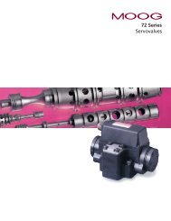
<strong>Servovalves</strong><strong>with</strong> <strong>integrated</strong> <strong>Electronics</strong><strong>D791</strong> <strong>and</strong> <strong>D792</strong> <strong>Series</strong>
<strong>D791</strong> <strong>and</strong> <strong>D792</strong> <strong>Series</strong>Three stage servovalvesThe flow control servovalves <strong>D791</strong><strong>and</strong> <strong>D792</strong> <strong>Series</strong> are throttle valvesfor 3-way <strong>and</strong> preferably 4-wayapplications. These three stageservovalves have been especiallydeveloped for such dem<strong>and</strong>ingapplications where high flow rates<strong>and</strong> at the same time extremedynamic performance requirementsmust be met. The design ofthese valves is based on the wellknown D079 <strong>Series</strong>. The <strong>integrated</strong>electronics has beenreplaced by a new design applyingSMD technology. The valves areoffered <strong>with</strong> pilot valves of D761or D765 <strong>Series</strong>, optional st<strong>and</strong>ardresponse or high response versionsare available. <strong>Series</strong> <strong>D791</strong> can deliverrated flow up to 250 l/min,<strong>Series</strong> <strong>D792</strong> is available <strong>with</strong> ratedflow up to 1000 l/min.These valves are suitable for pressureor force control, position <strong>and</strong>velocity control systems <strong>with</strong> highdynamic response requirements.Principle of operationAn electrical comm<strong>and</strong> signal (setpoint, input signal) is applied tothe <strong>integrated</strong> control amplifierwhich drives a current throughthe pilot valve coils. The pilot valveproduces differential pressure inits control ports. This pressuredifference results in a pilot flowwhich causes main spool displacement.The position transducer which isexcited via an oscillator measuresthe position of the main spool(actual value, position voltage).This signal then is demodulated<strong>and</strong> fed back to the controlamplifier where it is compared<strong>with</strong> the comm<strong>and</strong> signal. Thecontrol amplifier drives the pilotvalve until the error betweencomm<strong>and</strong> signal <strong>and</strong> feedbacksignal is zero. Thus, the position ofthe main spool is proportional tothe electrical comm<strong>and</strong> signal.Operational featuresr Electrical position feedback <strong>with</strong> pressure isolated positiontransducer (LVDT), no wearr Integrated SMD electronics <strong>with</strong> false polarity protectionr Optional external pilot supply <strong>and</strong> return connections via fifth<strong>and</strong> sixth port in valve bodyr Low threshold <strong>and</strong> hysteresis, excellent null stabilityr Preadjusted at factoryThe valves <strong>D791</strong> <strong>and</strong> <strong>D792</strong> <strong>Series</strong>described in this catalogue havesuccessfully passed EMC testsrequired by EC Directive. Pleasetake notice of the respectivereferences in the electronicssection.The actual flow depends on theelectrical comm<strong>and</strong> signal <strong>and</strong>the valve pressure drop, <strong>and</strong> maybe calculated using the squareroot function for a sharp-edgedorifice.The flow value Q calculated inthis way should not exceed anaverage flow velocity of 30 m/s inports P, A, B <strong>and</strong> T.Q = QNQ [l/min] = calculated flowQ N[l/min] = rated flowDp [bar] = actual valve pressuredropDp N[bar] = rated valve pressuredrop∆pIf large flow rates <strong>with</strong> high valvepressure drops are required, an∆p-2 QNappropriate higher pilot pressure p X ≥ 2,5⋅10⋅ ∆pAKhas to be chosen to overcome theflow forces. An approximate valuecan be calculated as follows:Q [l/min] = max. flowDp [bar] = valve pressure drop<strong>with</strong> QA K[cm 2 ] = spool drive area[bar] = pilot pressurep XThe pilot pressure p Xhas to be atleast 15 bar above the returnpressure of the pilot stage.Our quality management systemis certified in accordance <strong>with</strong>DIN EN ISO 9001.This catalogue is for users <strong>with</strong>technical knowledge. To ensurethat all necessary characteristicsfor function <strong>and</strong> safety of thesystem are given, the user has tocheck the suitability of theproducts described here.In case of doubt please contactMOOG.2
<strong>D791</strong> <strong>and</strong> <strong>D792</strong> <strong>Series</strong>General technical dataOperating pressure rangeMain stagePorts P, A <strong>and</strong> B<strong>with</strong> X internal<strong>with</strong> X externalPort T <strong>with</strong> Y internalPort T <strong>with</strong> Y externalup to 315 barup to 350 barup to 210 barup to 350 barPilot valvePorts P, A <strong>and</strong> BD761, D765 <strong>Series</strong> up to 315 barPort Tup to 210 barTemperature rangeAmbient -20 to +60 °CFluid -20 to +80 °CSeal materialFPM, others on requestOperating fluidMineral oil based hydraulic fluid(to DIN 51524), others on requestViscosityClass of cleanlinessrecommended 15 to 100 mm²/sThe cleanliness of the hydraulicfluid greatly effects the performance(spool positioning, highresolution) <strong>and</strong> wear (meteringedges, pressure gain, leakage) ofthe valve.Recommended cleanliness classfor normal operation: ISO 4406 < 14/11for longer life: ISO 4406 < 13/10System filtrationPilot valve:Main stage:Filter rating recommendedfor normal operation:for longer life:Installation optionsVibrationDegree of protectionShipping plateHigh pressure filter (<strong>with</strong>out bypass,but <strong>with</strong> dirt alarm) mountedin the mainflow <strong>and</strong> if possible,directly upstream of the servovalve.Main stage: high pressure filter asfor the pilot stage. In combination<strong>with</strong> a fast regulating VD-pump abypass filter is possible.ß 10³ 75 (10 µm absolute)ß 5³ 75 ( 5 µm absolute)any position, fixed or movable30 g, 3 axesEN 60529: IP 65 (<strong>with</strong> mating connectormounted)Delivered <strong>with</strong> an oil sealed shippingplate3 stage Servovalve<strong>D791</strong> / <strong>D792</strong> <strong>Series</strong> <strong>with</strong>Pilot valve D765 <strong>Series</strong>T B P A3
<strong>D791</strong> <strong>Series</strong>Technical dataModel . . . .Type <strong>D791</strong> . . . . S . . .Mounting pattern ISO, but X <strong>and</strong> Y do not corres- ISO 10372-06-05-0-92pond to ISOValve body version4-way3-stage <strong>with</strong> bushing spool assemblyPilot valve2-stage, optional D761 or D765 <strong>Series</strong>Pilot connection optional, internal or external X <strong>and</strong> YMass [kg] 13Rated flow(± 10%) at Dp N= 35 barper l<strong>and</strong> [l/min] 100 160 250Response time*for 0 to 100% stroke (dependenton pilot valve) [ms] 3 to 10Threshold* [%] < 0,2Hysteresis* [%] < 0,5Null shift <strong>with</strong> DT = 55 K [%] < 2Null leakage flow* total, max. [l/min] 5 7 10Pilot leakage flow*max., for 100% step input (dependenton pilot valve) [l/min] 4 to 11Main spool stroke [mm] 1,6 1,6 2,0Main spool drive area [cm²] 2,85* measured at 210 bar pilot or operating pressure, fluid viscosity of 32 mm²/s <strong>and</strong> fluid temperature of 40 °CTypical characteristic curves measured at 210 bar pilot or operating pressure, fluid viscosity of 32 mm²/s <strong>and</strong> fluid temperature of 40 °CValve flow diagramFrequency responsefor valves <strong>with</strong> different rated flows <strong>and</strong> different pilot valvesRated flow 100/160 l/minPilot valve D761 Std 10 l/minRated flow 100/160 l/minPilot valve D765 HR10 l/minValve flow for maximum valve opening (100% comm<strong>and</strong>signal) as a function of the valve pressure dropRated flow 250 l/minPilot valve D761 Std10 l/minRated flow 250 l/minPilot valve D761 HR 20 l/min4
<strong>D792</strong> <strong>Series</strong>Technical dataModel . . . .Type <strong>D792</strong> . . . . S . . .Mounting patternMoog St<strong>and</strong>ardValve body version4-way3-stage <strong>with</strong> bushing spool assemblyPilot valve2-stage, optional D761 or D765 <strong>Series</strong>Pilot connection optional, internal or external X <strong>and</strong> YMass [kg] 17Rated flow(± 10%) at Dp N= 35 barper l<strong>and</strong> [l/min] 400 630 800 1000Response time*for 0 to 100% stroke (dependenton pilot valve) [ms] 4 to 12Threshold* [%] < 0,2Hysteresis* [%] < 0,5Null shift <strong>with</strong> D T = 55 K [%] < 2Null leakage flow* total, max. [l/min] 10 14 14 14Pilot leakage flow*max., for 100% step input (dependenton pilot valve) [l/min] 6 to 16Main spool stroke [mm] 1,8 1,9 2,6 4,0Main spool drive area [cm²] 3,8 7,14 7,14 7,14* measured at 210 bar pilot or operating pressure, fluid viscosity of 32 mm²/s <strong>and</strong> fluid temperature of 40 °CTypical characteristic curves measured at 210 bar pilot or operating pressure, fluid viscosity of 32 mm²/s <strong>and</strong> fluid temperature of 40 °CValve flow diagramFrequency responsefor valves <strong>with</strong> different rated flows <strong>and</strong> different pilot valvesRated flow 400 l/minPilot valve D761 HR 20 l/minRated flow 630 l/minPilot valve D765 HR 20 l/minValve flow for maximum valve opening (100% comm<strong>and</strong>signal) as a function of the valve pressure dropRated flow 800 l/minPilot valve D761 HR 20 l/minRated flow 800 l/minPilot valve D765 HR 20 l/min5
<strong>D791</strong> <strong>Series</strong>Installation drawing <strong>with</strong>Pilot valve D761 <strong>Series</strong>Conversion instructionThe mounting manifold mustconform toISO 10372-06-05-0-92.Note: The X port to ISO St<strong>and</strong>ardmust not be machined.The X <strong>and</strong> Y ports of MOOGvalve body do not correspondto ISO St<strong>and</strong>ard.Mounting surface needs to beflat <strong>with</strong>in 0,02 mm. Averagesurface finish value, Ra, betterthan 1µm.P A B T G X Y F1 F2 F3 F4Ø16 Ø16 Ø16 Ø16 Ø8 Ø6 Ø6 M10 M10 M10 M10x 36,5 11,1 61,9 36,5 11,1 36,5 36,5 0 73 73 0y 17,4 42,8 42,8 68,2 23,7 -2,6 88,2 0 0 85,6 85,6Conversion instructionfor main stage operation <strong>with</strong>internal or external pilot connectionPilot flow Set screw M 6 x 6 Pilot flow Set screw M 6 x 6Supply Bore 1 Bore 2 Return Bore 3 Bore 4Internal P open closed Internal T open closedExternal X closed open External Y closed open6
<strong>D791</strong> <strong>Series</strong>Installation drawing <strong>with</strong>Pilot valve D765 <strong>Series</strong>Spare parts, AccessoriesSpare parts <strong>and</strong> accessories for <strong>D791</strong> <strong>Series</strong>O-rings (included in delivery)FPM 85 Shorefor P, T, A, B 4 pieces ID 20,3 x 1,78 42082 040for X, Y 2 pieces ID 7,65 x 1,78 42082 012Mating connector, waterproof IP 65 (not included in delivery) for cable dia6+PE-pole DIN 43563 min. Ø 10 mm, max. Ø 12 mm B97007 061Flushing plate (internal supply) 55118 001(external supply)A26133Mounting bolts (not included in delivery)M 10 x 50 DIN 912-10.9 4 pieces required torque 65 Nm A03665 100 050Replaceable filter for pilot valve 65 µm nominal A67999 065O-rings for filter replacementFPM 85 Shore2 pieces ID 13 x Ø 1,5 A25163 013 015Set screws for X <strong>and</strong> Y 2pieces M 6 x 6 DIN 13 66166 060 0067
<strong>D792</strong> <strong>Series</strong>Installation drawing <strong>with</strong>Pilot valve D761 <strong>Series</strong>Conversion instructionNote: The X <strong>and</strong> Y tubes have tobe connected to the MOOG valvebody by fittings.Mounting surface needs to be flat<strong>with</strong>in 0,02 mm. Average surfacefinish value, Ra, better than 1µm.P A B T G F1 F2 F3 F4 F5 F6 F7 F8Ø28 Ø28 Ø28 Ø28 Ø8 M16 M16 M16 M16 M16 M16 M16 M16x 55,4 15,8 95,0 55,4 55,4 0 110,8 110,8 0 31,5 79,3 79,3 31,5y 30,1 58,7 58,7 87,3 0 0 0 117,4 117,4 0 0 117,4 117,4Conversion instructionfor main stage operation <strong>with</strong>internal or external pilot connection(externally by tubes)Pilot flow Set screw 1 Screw Pilot flow Set screw 3 ScrewSupply NPTF 1/16 plug 2 Return NPTF 1/16 plug 4M14 x 1,5 M14 x 1,5Internal P open closed Internal T open closedExternal X closed Tube External Y closed Tube8
<strong>D792</strong> <strong>Series</strong>Installation drawing <strong>with</strong>Pilot valve D765 <strong>Series</strong>Spare parts, AccessoriesSpare parts <strong>and</strong> accessories for <strong>D792</strong> <strong>Series</strong>O-rings (included in delivery)FPM 85 Shorefor P, T, A, B 4 pieces ID 36 x 3,5 42082 264Mating connector, waterproof IP 65 (not included in delivery) for cable dia6+PE-pole DIN 43563 min. Ø 10 mm, max. Ø 12 mm B97007 061Flushing plate 76216 001Mounting bolts (not included in delivery) requiredM 16 x 60 DIN 912-10.9 8 pieces required torque 290 Nm A03665 160 060Replaceable filter for pilot valve 65 µm nominale A67999 065O-rings for filter replacementFPM 85 Shore2 pieces ID 13 x Ø 1,5 A25163 013 015Screw plug (X <strong>and</strong> Y ports) <strong>with</strong> seal 2 pieces M 14 x 1,5 66149 014Set screw (X <strong>and</strong> Y ports) 2 pieces 1 / 16 NPTF A03668 0019
<strong>D791</strong> <strong>and</strong> <strong>D792</strong> <strong>Series</strong>Valve electronics <strong>with</strong>supply voltage ± 15 VoltComm<strong>and</strong> signal 0 to ±10 VValves <strong>with</strong> voltage comm<strong>and</strong>inputThe spool stroke of the valve isproportional to (U D– U E). 100%valve opening P ç A <strong>and</strong> B ç T isachieved at (U D– U E) = +10 V. At0 V comm<strong>and</strong> the spool is in acentred position.The input stage is a differentialamplifier. If only one comm<strong>and</strong>signal is available, pin D or E isconnected to signal ground ^(pin C) according to the requiredoperating direction (to be done atthe mating connector).Comm<strong>and</strong> signal 0 to ±10 mAValves <strong>with</strong> current comm<strong>and</strong>inputThe spool stroke of the valve isproportional to (I D– I E). 100%valve opening P ç A <strong>and</strong> B ç T isachieved at (I D– I E) = +10 mA. At0 mA comm<strong>and</strong> the spool is in acentred position.Either pin D or E is used accordingto the required operating direction.The unused pin is left open(not connected at the mating connector).The input pins D <strong>and</strong> E areinverting.Actual value 0 to ±10 VValves <strong>with</strong> voltage comm<strong>and</strong>inputThe actual spool position valuecan be measured at pin F. Thissignal can be used for monitoring<strong>and</strong> fault detection purposes.The spool stroke range correspondsto ±10 V. 100% valve openingP ç A <strong>and</strong> B ç T correspondsto +10 V.Actual value 0 to ±10 mA or4 to 20 mAValves <strong>with</strong> current comm<strong>and</strong>inputThe actual spool position valuecan be measured at pin F. Thissignal can be used for monitoring<strong>and</strong> fault detection purposes.The spool stroke range correspondsto ±10 mA (4 to 20 mA).100% valve opening P ç A <strong>and</strong>B ç T corresponds to +10 mA(20 mA).General requirementsr Supply ± 15 VDC ± 3%. Ripple
<strong>D791</strong> und <strong>D792</strong> <strong>Series</strong>Ordering information<strong>D791</strong>, <strong>D792</strong>Model-Numbern n n n nnType designationnn n n n n n n n n n nSpecification status- <strong>Series</strong> specificationE Preseries specificationZ Special specificationModel designationassigned at the factoryFactory identificationassigned at the factoryValve versionS Servovalve 3-stageSupply voltage0 ± 15 VDC ± 3%, Ripple < 50 mV ppSignals for 100% spool strokeComm<strong>and</strong> OutputA ±10 V ±10 VB ±10 mA ±10 mAP ±10 mA 4 to 20 mAValve connectorS 6 + PE-pole DIN 43563Rated flowQ N[l/min] at Dp N= 35 bar per l<strong>and</strong> <strong>Series</strong>10 100 <strong>D791</strong>16 160 <strong>D791</strong>25 250 <strong>D791</strong>40 400 <strong>D792</strong>63 630 <strong>D792</strong>80 800 <strong>D792</strong>99 1 000 <strong>D792</strong>Maximum operating pressure p PJ 315 bar. At p X£ 315 bar (X <strong>and</strong> Y external) operating pressurein ports P, A, B <strong>and</strong> T up to 350 bar possibleK 350 barMain spool typeO 4-way: axis cut, linear characteristicSeal materialU FPM (Viton), PUR (Ultrathan) only for bushing, only <strong>D791</strong>V FPM (Viton) only <strong>D792</strong>others on requestPilot connections <strong>and</strong> pressurePressure Supply Return[bar] X YE 15 to 315 internal internalF 15 to 315 external externalG 15 to 315 external internalH 15 to 315 internal externalJ 25 to 350 internal internalK 25 to 350 external externalL 25 to 350 external internalM 25 to 350 internal externalPilot valveP D761 St<strong>and</strong>ardQ D761 High responseR D765 High responseS D765 St<strong>and</strong>ardSpool position of main stage <strong>with</strong>out electrical supplyPosition Pilot pressure [bar]O undefined ³15A P ç B, A ç T ³15B P ç A, B ç T ³15Preferred configurations are highlighted.All combinations may not be available.Options may increase price.Technical changes are reserved.11
Australia MelbourneAustriaViennaBrazil São PauloDenmark BirkerødEngl<strong>and</strong> TewkesburyFinl<strong>and</strong> EspooFranceRungisGermany BöblingenHong Kong Kwai ChungIndiaBangaloreIrel<strong>and</strong> RingaskiddyItaly MalnateJapan HiratsukaKorea KwangjuPhilippines BaguioRussia PavlovoSingapore SingaporeSpain OrioSweden GotenborgUSA East Aurora (NY)BAM/WA/3000 Printed in GermanyMOOG Controls LimitedAshchurchTewkesburyGloucestershireGL20 8NATelephone (01684) 29 66 00Telefax (01684) 29 67 60MOOG GmbHHanns-Klemm-Straße 28D - 71034 BöblingenPostfach 1670D - 71006 BöblingenTelefon (07031) 622-0Telefax (07031) 622-191<strong>D791</strong>/2 - En / Rev1 / 05.98