1SDC210018D0201 - SACE, Isomax, Emax, Tmax
1SDC210018D0201 - SACE, Isomax, Emax, Tmax
1SDC210018D0201 - SACE, Isomax, Emax, Tmax
- No tags were found...

Create successful ePaper yourself
Turn your PDF publications into a flip-book with our unique Google optimized e-Paper software.
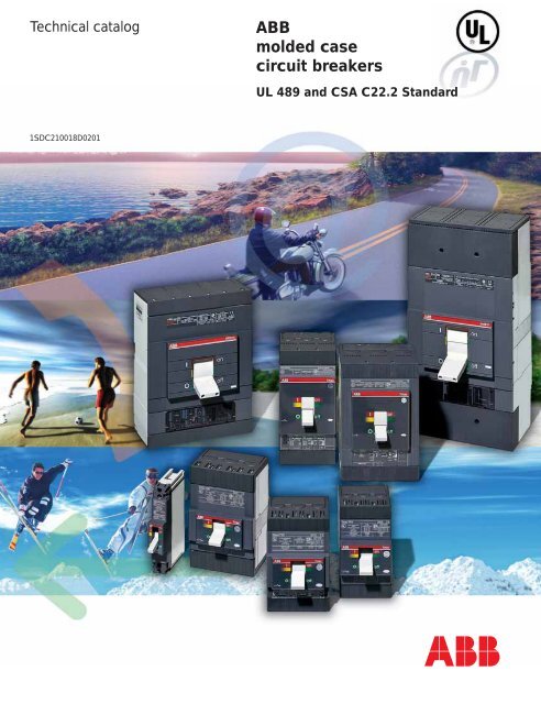
Technical catalogABBmolded casecircuit breakersUL 489 and CSA C22.2 Standard<strong>1SDC210018D0201</strong>
VERVIEWMAINCHARACTERISTICSTHE RANGESACCESSORIESCHARACTERISTIC CURVESAND TECHNICALINFORMATIONWIRING DIAGRAMSOVERALLDIMENSIONSORDERINGCODES
COMPLETE AND PERFECTLY INTEGRATEDIn the range of molded case circuit breakers conforming with the UL 489 and CSA C22.2 Standard, ABB proposes anentire range which covers current ratings between 15 A and 2500 A and interrupting ratings, at 480 V AC, which canreach 150 kA.The ranges available are as follows:– circuit breakers for power distribution (fitted with thermomagnetic or electronic trip units starting from 100 A)– circuit breakers with adjustable magnetic only trip units for motor protection (MCP: Motor Control Protection)– molded case switches for use as isolators or switching devices for lines, busbars or parts of a plant (MCS:Molded Case Switch)With the introduction of the new <strong>Tmax</strong> UL series, a single-pole circuit breaker with interrupting rating of 18 kAat 277 V AC is available on the American market for the first time.480 VAll ABB circuit breakers in accordance with theUL 489 and CSA C22.2 Standard can beused in installations with wye or deltadistribution systems since use of the circuitbreaker at 480 V AC is guaranteed, evenfor the smallest <strong>Tmax</strong> T1 size.COMPACT DIMENSIONSABB molded case circuit breakers ensurehigh performances in extremely small andcompact dimensions. Standardization ofthe depth of the smaller sizes allows morerational and less deep enclosure to be usedthan in the past.DOUBLE INSULATIONThanks to the double insulation technique,with all ABB molded case circuit breakers*the electrical accessories can be mounteddirectly on field with the circuit breakerinstalled: this allows considerable savings intime and therefore in costs.* Except for <strong>Isomax</strong> S8.
GENERATION<strong>Tmax</strong> hasgrown. ABBexperience in designing andmanufacturing molded casecircuit breakers has made itpossible to create circuit breakerswhich, up to 600 A, allow any application to befaced practically and simply.The new <strong>Tmax</strong> have been thought up to worktogether, to help you carry out selections andcorrect sizing, to make installation simpler, butabove all to give you top level performances.The latest generation technology is present forthe first time even in the smallest sizes.With <strong>Tmax</strong> you have everything you need athand to make your job easier, from all types ofaccessories and terminals. The T Generation grows,TMAX.BE FREE.and so does freedom.The <strong>Tmax</strong> T4 and T5 circuitbreakers have obtained theprestigious “INTEL Design 2003– Augusto Morello award” in theProduct Technologies andProduction processes section.
ECHNOLOGYIt was not easy to find solutions which would allow the<strong>Tmax</strong> circuit breakers to achieve such high performancesin such limited dimensions, but thanks to theexperience which has been recognised to a leaderTMAX.BE FREE TORIDE THE MOSTADVANCEDTECHNOLOGY.such as ABB for decades, the objectives we had setourselves have been achieved. So this has meantbeing able to equip such a small circuit breakeras the T2 with an electronic trip unit, to fit thecircuit breakers with new arcing chamberswhich allow the arc extinction time to bereduced, or, still further, to provide doubleinsulation for ever greater safety right from thesmallest size. A complete series of latestgeneration trip units is available, from theelectronic to the thermomagnetic or magneticonly ones - all interchangeable.The new <strong>Tmax</strong> T4 and T5 are an example of thegreat technology expressed by this family of circuitbreakers with high breaking capacity and highlimitation of the specific let-through energy.Being free is also all this.
IZINGAll the circuit breakers in the <strong>Tmax</strong> family come fromoptimisation of installation sizing. With T1,T2 and T3you can find the ideal product for sizing an installationup to 225 A, and with T4 and T5 up to 600 A.Furthermore, with the latter, high selectivity valuesare obtained for optimal coordination with othercircuit breakers. You can also choose the bestTMAX.BE FREE TOCHOOSEOPTIMAL SIZING.solution for motor protection with the motorcontrol protection (MCP).Higher performances in less space. Moreapplications up to 600 A. Easier selection of thecircuit breakers and accessories. Optimal sizing ofthe installation and better protection of cables,busbar ducts and supports. Less space required inthe switchgear and in the metal structures.Less oversizing and therefore lower costs.Less time for coordinating the installations.Fewer stock complications. With <strong>Tmax</strong>, all thesolutions needed can be chosen, as well as thatof feeling freer to choose.
NSTALLATIONHaving circuit breakers available with smaller dimensionsthan all the others on the market undoubtedly offersgreat advantages - more space for cabling operations andTMAX.BE FREE TODRIBBLE ROUNDALL INSTALLATIONDIFFICULTIES.simpler installation, therefore notable savings in time -five sizes, just two depths - 2.76 inches (70 mm) forT1, T2, T3 and 4.07 inches (103.5 mm) for T4and T5, and the latter also have the same height.They are also available in all the versions: fixed,plug-in and draw out and, thanks to special kits,passing from a fixed circuit breaker to a plug-in/draw out one is child’s play. Flexibility of use overthe whole series is ensured by the complete rangeof connection terminals and by the large numberof accessories.Being free also means having much more timefor yourself.
100% UL RATED CIRCUIT BREAKERSThe 100% rated versions for <strong>Isomax</strong> circuit breakers are available thanks to the excellent thermal sizing ofthe latter.ALL THE APPLICATIONSABB offers the right solution for any application up to 2500 A thanks to <strong>Isomax</strong> S6, S7 and S8 circuitbreakers, perfectly integrated with the <strong>Tmax</strong> family:– MCCB: S6, S7 and S8 molded case circuit breakers for power distribution;– MCP: S6, S7 and S8 circuit breakers with magnetic only trip unit for motor control protection;– MCS: S6, S7 and S8 molded case switches for using as isolators or switching devices for lines, busbars orparts of plants.MAXIMUM VERSATILITY<strong>Isomax</strong> circuit breakers can be fitted with a wide range ofterminals for every kind of connections. Modular designalso makes installation and assembly extremely simple.COMPLETE RANGE OF ACCESSORIES<strong>Isomax</strong> circuit breakers are complemented by acomplete range of accessories to satisfy the widelydiffering operational and automation requirements.Accessories are standardized for groups of circuitbreakers to streamline storage logistics and simplifyinstallation.<strong>Isomax</strong> circuit breakers can be customized as requiredunder conditions of absolute safety.All the accessories can be mounted with simpleoperations without exposing the main contacts (except forthe <strong>Isomax</strong> S8).
Circuit breakers for power distributionElectrical characteristics<strong>Tmax</strong> T1 1P <strong>Tmax</strong> T1 <strong>Tmax</strong> T2 <strong>Tmax</strong> T3IEC 60947-2Rated uninterrupted current, Iu [A] 160 160 160 250Number of poles [Nr] 1 3,4 3,4 3,4Rated service voltage, Ue AC (50-60Hz) [V] 240 690 690 690DC [V] 125 500 500 500Rated ultimate short circuit breaking capacity, Icu B B C N N S H L N SAC (50-60 Hz) 220/230 V [kA] 25 25 40 50 65 85 100 120 50 85380/415 V [kA] 16 25 36 36 50 70 85 36 50440 V [kA] 10 15 22 30 45 55 75 25 40500 V [kA] 8 10 15 25 30 36 50 20 30690 V [kA] 3 4 6 6 7 8 10 5 8DC 250 V - 2 poles in series [kA] 16 25 36 36 50 70 85 36 50250 V - 3 poles in series [kA] 20 30 40 40 55 85 100 40 55500 V - 2 poles in series [kA]500 V - 3 poles in series [kA] 16 25 36 36 50 70 85 36 50750 V - 3 poles in series [kA]Trip units TMF ■TMD/TMA ■ ■ ■ELTMF<strong>Tmax</strong> T1 1P <strong>Tmax</strong> T1 <strong>Tmax</strong> T2 <strong>Tmax</strong> T3UL 489 CSA C22.2Frame size [A] 100 100 100 225Number of poles [Nr] 1 3,4 3,4 3,4Rated voltage AC (50-60Hz) [V] 277 600Y/347 480 600Y/347DC [V] 500 500Interrupting ratings B N S H N SAC 240 V [kA] 50 (2) 65 100 50 65277 V [kA] 18 (1)480 V [kA] 22 (2) 35 65 25 35600Y/347 V [kA] 10 10 10600 V [kA]DC 250 V - 2 poles in series [kA] 25 25 35500 V - 3 poles in series [kA] 25 25 35500 V - 2 poles in series [kA]600 V - 3 poles in series [kA]Trip units TMF ■ ■ ■ ■TMD/TMAELTMA ■ ■Versions MCCB ■ ■ ■ ■MCS ■ ■MCP ■ ■MA ■ ■■■■UL 489 CSA C22.2 and IEC 60947-2Dimensions H [in/mm] 5.12/130 5.12/130 5.12/130 5.9/150W 1p or 3p [in/mm] 1/25.4 3/76 3.54/90 4.13/105W 4p [in/mm] 4/102 4.72/120 5.51/140D [in/mm] 2.76/70 2.76/70 2.76/70 2.76/70Mechanical life [No.operations] 25000 25000 25000 25000[No. Hourly operations] 240 240 240 240Electrical life @ 415 V AC [No.operations] 8000 8000 8000 8000[No. Hourly operations] 120 120 120 120(1)In15A = 10kA @ 277 V AC(2)In15A = 35 kA @ 240 V AC, 14 kA @ 480Y/277 V ACTMF = Thermomagnetic trip unit with fixed thermaland magnetic thresholdTMD = Thermomagnetic trip unit with adjustablethermal threshold and fixed magneticthreshold
<strong>Tmax</strong> T4 <strong>Tmax</strong> T5 <strong>Isomax</strong> S6 <strong>Isomax</strong> S7 <strong>Isomax</strong> S8250 400 - 600 800 1200 1600, 2000, 25003,4 3,4 2,3,4 2,3,4 3600 600 600 600 600600 600 600N S H L V N S H L V N H L H V65 100 150 200 200 65 100 150 200 200 65 150 200 100 12525 35 65 100 150 25 35 65 100 150 50 65 100 65 10018 25 35 65 100 18 25 35 65 100 25 35 42 50 8525 35 50 65 100 25 35 50 65 100 35 50 6516 25 35 50 65 16 25 35 50 65 20 35 50■■ ■ ■■ ■ ■ ■ ■■ ■ ■ ■ ■■ ■ ■ ■ ■■ ■ ■ ■ ■<strong>Tmax</strong> T4 <strong>Tmax</strong> T5 <strong>Isomax</strong> S6 <strong>Isomax</strong> S7 <strong>Isomax</strong> S8250 - 320 400 - 630 630 - 800 1250 - 1600 2000, 2500, 32003,4 3,4 3,4 3,4 3,4690 690 690 690 690750 750 750N S H L V N S H L V N S H L S H L H V70 85 100 200 300 70 85 100 200 300 65 85 100 200 85 100 200 85 12036 50 70 120 200 36 50 70 120 200 35 50 65 100 50 65 100 85 12030 40 65 100 180 30 40 65 100 180 30 45 50 80 40 55 80 70 10025 30 50 85 150 25 30 50 85 150 25 35 40 65 35 45 70 50 7020 25 40 70 80 20 25 40 70 80 20 22 25 30 20 25 35 40 5036 50 70 120 200 36 50 70 120 200 35 50 65 10025 36 50 70 100 25 36 50 70 100 20 35 50 6516 25 36 50 70 16 25 36 50 70 16 20 35 50■ ■ ■■ ■ ■ ■ ■■8.07/205 8.07/205 10.55/268 15.98/406 15.75/4004.13/105 5.51/140 8.27/210 8.27/210 15.98/4065.51/140 7.24/184 11.02/280 11.02/280 21.89/5564.07/103.5 4.07/103.5 4.07/103.5 5.45/138.5 9.53/24220000 20000 20000 10000 10000240 120 120 120 208000(250A)-6000(320A) 7000(400A)-5000(630A) 7000(630A)-5000(800A) 7000(1250A)-5000(1600A) 2500(2500A)-1500(3200A)120 60 60 20 20(2500A)-10(3200A)TMA = Thermomagnetic trip unit with adjustablethermal and magnetic thresholdMFMA= Magnetic fixed trip unit= Magnetic adjustable trip unitELT = Electronic trip unit
Circuit breakers for specificapplications in accordance withIEC 60947-2<strong>Tmax</strong> T1 1P <strong>Tmax</strong> T1 <strong>Tmax</strong> T2 <strong>Tmax</strong> T3Circuit breakers for distribution AC-DCRated uninterrupted current [A] 160 160 160 225Numbers of poles Nr 1 3/4 3/4 3/4Rated voltage (AC) 50-60Hz [V] 240 690 690 690Icu [kA rms] B B C N N S H L N S380/415 V AC [kA rms] 25* 16 25 36 36 50 70 85 36 50440 V AC [kA rms] 10 15 22 30 45 55 75 25 40690 V AC [kA rms] 3 4 6 6 7 8 10 5 8Ics/Icu @ 380/415 V AC % 100 100 50 100 100 100 75 75 50Dimensions fixed version (3p) H [in-mm] 5.12-130 5.12-130 5.12-130 5.0-150W [in-mm] 1-25.4 3-76 3.54-90 4.13-105D [in-mm] 2.76-70 2.76-70 2.76-70 2.76-70Circuit breakers for motor protectionIu [A] 160 250Poles 3 3In [A] 1…100 100…200Ue [V] 690 690Trip unit Adjustable magnetic only (6…12xIn) ■ ■Electronic PR221DS-I ■PR222/MP (IEC 60947-4-1)PR212/P-IPR212/MP (IEC 60947-4-1)T2T3Switch-disconnectorsPoles [Nr] 3/4 3/4Ith [A] 160 250Ue [V] 690 690Uimp [KV] 8 8Ui [V] 800 800Icm [KA] 2.8 5.3Icw (1s) [KA] 2 3.6* For In 16A and In 20A: Icu @ 220/230 V AC = 16 KAT1DT3D
<strong>Tmax</strong> T4 <strong>Tmax</strong> T5 <strong>Isomax</strong> S6 <strong>Isomax</strong> S7 <strong>Isomax</strong> S8250 400-630 800 1250-1600 2000-2500-32003/4 3/4 3/4 3/4 3/4690 690 690 690 690N S H L V N S H L V N S H L S H L H V36 50 70 120 200 36 50 70 120 200 35 50 65 100 50 65 100 85 12030 40 65 100 180 30 40 65 100 180 30 45 50 80 40 55 80 70 10020 25 40 70 80 20 25 40 70 80 20 22 25 30 20 25 35 40 50100 100 100 100 100 100 100 100 100 100 100 100 100 75 100 75 50 50 508.07/205 8.07/205 14.25-268 16-406 15.75-4004.13/105 5.51/140 8.27-210 8.27-210 15.98-4064.07/103.5 4.07-103.5 4.07-103.5 5.45-138.5 9.25-235T4 T5 S7250 400 1250-16003 3 380…250 320-400 1000…1600690 690 690■■■■■■■T4D T5D S6D S7D S8D3/4 3/4 3/4 3/4 3/4250-320 400-630 800 1000-1250-1600 2000-2500-3200690 690 690 690 6908 8 8 8 8800 800 800 800 8005.3 11 30 52.5 853.6 6 15 25 40
Main characteristics1IndexGeneral information ........................................................................................................... 1/3Construction characteristicsModularity of the series ....................................................................................................... 1/4Distinguishing features of the series .................................................................................... 1/6ABB 1/1
General information227211191823 2014171615514631082129713111/2ABB
24The ABB family of molded case circuit breakers in conformity withUL 489 and CSA C22.2 No. 5.1 Standard - <strong>Tmax</strong> and <strong>Isomax</strong> - isdivided into different, perfectly integrated, ranges (<strong>Tmax</strong> T1B 1p,T1, T2, T3, T4, T5 and <strong>Isomax</strong> S6, S7, S8), able to cover a rangeof service currents from 15 to 2500 A.The power distribution circuit breakers are available, with UL 489and CSA C22.2 approval, in the fixed, plug-in or draw out, twopole,three-pole and four-pole versions.The <strong>Tmax</strong> T1 circuit breaker is also available in the single pole<strong>Tmax</strong> T1B 1p version, with an interrupting rating of 18 kA at 277 VAC. The circuit breakers can be selected among different interruptingrating levels from 22 kA to 150 kA at 480 V AC and from18 kA up to 100 kA at 600 V AC.125Starting from the fixed version circuit breaker, all the other versionsused for various requirements are obtained by means ofmounting conversion kits.The following are available:– kit for converting a fixed circuit breaker into the moving part ofa plug-in and draw out one– circuit breaker fixed parts for plug-in and draw out circuitbreakers– conversion kit for the connection terminals.Various accessories are also available:1. Breaking unit (1)2. Trip units (1)3. Front4. Auxiliary contacts - AUX (2)5. Undervoltage release - UVR (2)6. Shunt trip - SOR (2)7. Terminal covers8. Front for lever operating mechanism - FLD (2)9. Direct rotary handle - RHD (2)10. Stored energy motor operator - MOE (2)11. Key lock - KLF12. Early auxiliary contact - AUE13. Transmitted rotary handle - RHE (2)14. Front terminal for copper cable - FC Cu (UL listed for <strong>Tmax</strong> T1)15. Front extended terminal - EF16. Multi-cable terminal (only for T4) - MC17. Front terminal for copper-aluminium - FC CuAl (UL listed)18. Front extended spread terminal - ES19. Rear orientated terminal - R20. Conversion kit for plug-in/draw out versions (2)21. Guide of fixed part in the draw out version (2)22. Fixed part - FP (2)23. Auxiliary position contact - AUP24. Phase separators25. PR010T26. TT127. Racking out crank28. Residual current release.2627281SDC210141F0023(1)UL file E93565(2)UL file E116596ABB1/3
Construction characteristicsDistinguishing features of the series11SDC210142F0023Compliance with Standards and companyQuality SystemThe <strong>Tmax</strong> and <strong>Isomax</strong> circuit breakers and their electrical accessoriesconform to the UL 489 (Underwriters Laboratories Incorporated)and CSA C22.2 No.5.1 (Canadian Standard Association)North American Standards, and to the international IEC 60947-2Standards and comply with the EC directive:– “Low Voltage Directives” (LVD) no. 73/23 EEC– “Electromagnetic Compatibility Directive” (EMC) no.89/336 EEC.Certification of compliance with the above-mentioned productStandards is carried out, in respect of the European EN 45011Standard, by the Italian certification body ACAE (Association forCertification of Electrical Apparatus), a member of the EuropeanLOVAG organization (Low Voltage Agreement Group).The ABB test laboratory is accredited by SINAL (certificate no.062/2002).The ABB Quality System complies with the international ISO 9001- 2000 Standard (model for quality assurance in design, development,construction, installation and service) and with the equivalentEuropean EN ISO 9001 and Italian UNI EN ISO 9001 Standards.The independent certifying Body is RINA S.p.A. ABB obtained itsfirst certification with three-year validity in 1990, and has nowreached its fourth reconfirmation.The new <strong>Tmax</strong> series has a hologram on the front, obtained usingspecial anti-imitation techniques, which guarantees the quality andthat the circuit breaker is an original ABB product.Attention to protection of the environment and to health and safetyin the work place is another priority commitment for ABB and, asconfirmation of this, the company environmental management systemhas been certified by RINA in 1997, in conformity with theinternational ISO 14001 Standard. This certification has been integratedin 1999 with the Management System for Healt and Safetyin the workplace, according to OHSAS 18001 (British Standards),obtaining one of the first certification of integrated managementSystem, QES (Quality, Environment, Safety) issued by RINA.ABB - the first industry in the electromechanical section in Italy toobtain this recognition - thanks to a revision of the production processwith an eye to ecology, has been able to reduce the consumptionof raw materials and waste from processing by 20%.ABB’s commitment to safeguarding the environment is also shownin a concrete way by the Life Cycle Assessments of its productscarried out directly by the ABB Research and Development in collaborationwith the ABB Research Center. Selection of materials,processes and packing materials is made optimising the true environmentalimpact of the product, also foreseeing the possibilityof its being recycled.1/4ABB
Double insulation *This construction characteristic consists of the presence of double insulation between the live powerparts (excluding the terminals) and the front parts of the apparatus where the operator works duringnormal operation of the installation. The seat of each electrical accessory is completely segregatedfrom the power circuit, thereby preventing any risk of contact with live parts, and, in particular, theoperating mechanism unit is completely insulated in relation to the powered circuits. As a consequencemost accessories are field installable.Furthermore, the insulation distances, both between the live internal parts and in the terminal connectionarea, comply with what is foreseen by the UL 489 Standard and are higher than thoserequired by the international IEC Standards.1* Except for <strong>Isomax</strong> S81SDC210143F0023Positive operationThe operating lever always indicates the exact positionof the circuit breaker moving contacts, therebyguaranteeing safe and reliable signals in compliancewith the prescriptions of the IEC 60417-2 Standard(I = Closed; O = Open; yellow-green line = Open due torelease trip). The circuit breaker operating mechanismhas trip free operation. Trip unit intervention automaticallyopens the moving contacts: to close them again,the operating mechanism must be reset by pushingthe operating lever from the intermediate position intothe lowest open position.1SDC210144F0023Isolation behaviourIn the open position, the circuit breakerguarantees circuit isolation in compliancewith the IEC 60947-2 Standard. The oversizedinsulating distances guarantee thereare no leakage currents and dielectricresistance to any overvoltages betweeninput and output. For plug in and draw outversion circuit breakers, in the racked-outposition, the power and auxiliary circuits areinsulated, guaranteeing that no part is live. By means of special socket-plugs, it is possible to carryout blank tests under these conditions, operating the circuit breaker in complete safety.1SDC210145F0023ABB1/5
Construction characteristicsDistinguishing features of the series1Operating temperatureThe <strong>Tmax</strong> and <strong>Isomax</strong> circuit breakers can be used in ambientconditions where the surrounding air temperature varies between–13 °F and +158 °F (–25 °C and +70 °C) and stored in ambientwith temperatures between –40 °F and + 158 °F (–40 °C and+70 °C). The circuit breakers fitted with thermomagnetic trip unithave their thermal element set for a reference temperature of104 °F (40 °C).For temperatures other than 104 °F (40 °C), with the same setting,there is a variation of the thermal threshold as shown in the tableson page 4/38 and 4/39.The electronic PR211/P, PR212/P, PR221DS and the newPR222DS/P electronic trip units do not undergo any variations inperformance as the temperature varies but, in the case of temperaturesexceeding 104 °F (40 °C), the maximum setting for protectionagainst overloads, L, must be reduced, as indicated in thederating graphs on page 4/37, to take into account the heatingphenomena which occur in the copper parts of the circuit breakerpassed through by the phase current. For temperature above158 °F (70 °C) the circuit breaker performances are not guaranteed.1SDC210146F00231/6ABB
AltitudeUp to an altitude of 6600 ft (2000 m) the <strong>Isomax</strong> and <strong>Tmax</strong> do notundergo any alterations in their rated performances. As the altitudeincreases, the atmospheric properties are altered in terms ofcomposition, dielectric resistance, cooling capacity and pressure.For this reason, the rated voltage and the nominalcurrent at this altitudes must be derated to the values shown inthe table.Altitude [ft] 6600 9900 13200 16500Ratedvoltage [V] 600 522 435 348Continuouscurrentrating % 100 98 93 9011SDC210147F0023Electromagnetic compatibilityWith the use of the PR211/P, PR212/P, PR221DS and PR222DS/Pelectronic trip units and the RC211, RC212, RC221, RC222 andRC223 electronic residual current releases, operation of the protectionsis guaranteed in the presence of interferences caused by electronicapparatus, atmospheric disturbances or electrical discharges.No interference with other electronic apparatus near the placeof installation is generated either. This is in compliance with theIEC 60947-2 Appendix F Standards and European DirectiveNo. 89/336 regarding EMC – electromagnetic compatibility.ABB1/7
Construction characteristicsDistinguishing features of the series1TropicalizationCircuit breakers and accessories in the ABB family of moldedcase circuit breakers have been tested in compliance with theIEC 60068-2-30 Standard, carrying out two cycles at 131 °F(55 °C) with the “variant 1” method (clause 6.3.3). The suitabilityof their use under the most severe environmental conditions istherefore ensured with the hot-humid climate defined inclimatograph 8 of the IEC 60721-2-1 Standards thanks to:– insulating cases made of synthetic resins reinforced with glassfibers;– anti-corrosion treatment of the main metallic parts– Fe/Zn 12 galvanization (ISO 2081), protected by a conversionlayer mainly consisting of chromates (ISO 4520)– application of anti-condensation protection for electronic trip units and relative accessories.1SDC210148F0023Resistance to shocks and vibrationsThe circuit breakers are unaffected by vibrations generated mechanically and due to electromagneticeffects, in compliance with the IEC 60068-2-6 Standards and the regulations of the majorclassification organizations:– ABS (American Bureau of Shipping)*– RINA– Det Norske Veritas– Bureau Veritas– Lloyd’s register of shipping– Germanischer Lloyd.The <strong>Isomax</strong> and <strong>Tmax</strong> circuit breakers are also tested, according to the IEC 60068-2-27 Standard,to resist shocks up to 12g.Please contact ABB for information regarding the types of circuit breakers approved, the performancesapproved and their relative validity.*Most of ABB circuit breakers are certified with ABS approval, according to IEC 60947-2; the whole <strong>Tmax</strong> family has ABSapproval according both with IEC 60947-2 and UL 489.1/8ABB
InstallationMolded case circuit breakers can beinstalled in the switchboards, mountedin any horizontal, vertical or lying downposition on the back plate or on rails,without undergoing any derating oftheir rated characteristics (1) . ABB circuitbreakers can be installed easily inall types of switchboards, above allthanks to the possibility of being suppliedeither by top or bottom terminals, without jeopardising the apparatus functionality.Apart from fixing on the base plate, T1, T2 and T3 can also be installed on DIN 50022 rails, thanks tothe special fixing brackets. Furthermore, the depth of 2.76 inches (70 mm) takes <strong>Tmax</strong> T3 to thesame standard as the two smaller sizes, making assembly of circuit breakers up to 225 A in standardswitchboards even simpler. In fact, it is possible to prepare standardised support structures, facilitatingthe design stage and construction of the switchboard metalwork.1SDC210150F002311SDC210151F0023(1)<strong>Isomax</strong> S8 can be mounted just in vertical position.Racking-out with the door closedWith <strong>Tmax</strong> T4 and T5 and <strong>Isomax</strong> S6 and S7 in the draw out version, the circuit breaker can beracked-in and out with the compartment door closed, thereby increasing operator safety and allowingrationalisation of low voltage arc proof switchboards. Racking out can only be carried out withthe circuit breaker open (for obvious safety reasons), using a special racking-out crank supplied withthe conversion kit from fixed circuit breaker to moving part of draw out circuit breaker.1SDC210152F0023ABB1/9
The rangesIndexCircuit breakers for power distributionElectrical characteristics ........................................................................................................ 2/2General characteristics .......................................................................................................... 2/42Thermomagnetic trip units ..................................................................................................... 2/6Electronic trip units ................................................................................................................ 2/8Motor control protection circuit breakers: MCPMagnetic and electronic overcurrent trip units .................................................................... 2/18Molded case switches: MCSElectrical characteristics ...................................................................................................... 2/20ABB 2/1
Circuit breakers for power distributionElectrical characteristics2T1 1P T1 T2 T3Frame size [A] 100 100 100 225Numbers of poles Nr 1 3-4 3-4 3-4Rated voltage (AC) 50-60Hz [V] 277 600Y/347 480 600Y/347(DC) [V] 500 500Test voltage (1min) 50-60 Hz [V] 3000 3000 3000 3000Interrupting ratings [kA rms] B N S H N S240 V AC [kA rms] 50 (2) 65 150 50 65277 V AC [kA rms] 18 (1)480 V AC [kA rms] 22 35 65 25 35600Y/347 V AC [kA rms] 10 10 10600 V AC [kA rms]250 V DC (2 poles in series) [kA rms] 25 25 35500 V DC (3 poles in series) [kA rms] 25 25 35500 V DC (2 poles in series) [kA rms]600 V DC (3 poles in series) [kA rms]Trip units Thermomagnetic ■ ■ ■ ■Electronic■Dimensions fixed version (3p) H [in-mm] 5.12-130 5.12-130 5.12-130 5.9-150W [in-mm] 1-25.4 3-76 3.54-90 4.13-105D [in-mm] 2.76-70 2.76-70 2.76-70 2.76-70Mechanical life [operations] 25000 25000 25000 25000Weights (fixed 3p) [lbs] 1.06 2.34 2.86 5.45Note: for S6 4 poles only for N versions(1)In 15A = 10 KA @ 277 V AC(2)In 15A = 35 KA @ 240 V AC 14 KA @ 480Y/277 V AC(3)Ask ABB for <strong>Tmax</strong> two-pole version availability2/2ABB
T4 T5 S6 S7 S82250 400-600 800 1200 1600-2000-25003-4 3-4 2-3-4 2-3-4 3600 600 600 600 600600 600 6003500 3500 3000 3000 3000N S H L V N S H L V N H L H V65 100 150 200 200 65 100 150 200 200 65 150 200 100 12525 35 65 100 150 25 35 65 100 150 50 65 100 65 10018 25 35 65 100 18 25 35 65 100 25 35 42 50 8525 35 50 65 100 25 35 50 65 100 35 50 6516 25 35 50 65 16 25 35 50 65 20 35 50■ ■ ■■ ■ ■ ■ ■8.07/205 8.07/205 10.55-268 16-406 15.75-4004.13/105 5.51/140 8.27-210 8.27-210 15.98-4064.07/103.5 4.07-103.5 4.07-103.5 5.45-138.5 9.25-23520000 20000 20000 10000 100006.18 8.55 22 37.5 135ABB 2/3
Circuit breakers for power distributionGeneral characteristicsGeneral characteristics2The ABB family of molded case circuit breakers, complying withthe UL 489 and CSA C22.2 No. 5.1 Standards, is divided intodifferent sizes, with an application range from 15 to 2500 A andinterrupting ratings up to 150 kA at 480 V AC.Selection of the size allows the basic electrical characteristics tobe identified simply and immediately, whereas selection of theovercurrent trip unit is made according to the type of applicationrequired.Furthermore, for the first time ABB has also developed a moldedcase circuit breaker with a single-pole construction characteristic:T1B 1p. This is a 100 A frame size circuit breaker, able to operateat rated voltages up to 277 V AC.For protection of alternating current networks, the following areavailable:– <strong>Tmax</strong> T1B 1p, T1, T2, T3 and T4 (15 A, 20 A) circuit breakers,equipped with TMF thermomagnetic trip units, with fixed thermaland magnetic threshold (I 3= 10 x In);– <strong>Tmax</strong> T4 (up to 50 A) circuit breaker equipped with TMDthermomagnetic trip units with adjustable thermal threshold(I 1= 0.7…1 x In) and fixed magnetic threshold (I 3= 10 x In).– T4, T5 and <strong>Isomax</strong> S6 circuit breakers with TMA thermomagnetictrip units, with adjustable thermal threshold (I 1= 0.7…1 xIn) and adjustable magnetic threshold (I 3= 5…10 x In).– T2 with PR221DS electronic trip unit– T4 and T5 with PR221DS, PR222DS/P and PR222DS/PD-Aelectronic trip unit– <strong>Isomax</strong> S6, S7 and S8 with PR211/P and PR212/P electronictrip unit.Interchangeability<strong>Tmax</strong> T4 and T5 circuit breakerscan be equipped eitherwith TMD or TMA thermomagnetictrip units, PR221DS,PR222DS/P and PR222DS/PD-A electronic trip units.Thanks to their simplicity of assembly,the end customer can,in fact, change the type of tripunit extremely rapidly, accordingto their own requirementsand needs: in this case, correctTrip unitTMF TMD TMACircuit breakersIn [A] 15 20 30 40 50 80 100 125 150 200 250 300 400T4 250 ■ ■ ■ ■ ■ ■ ■ ■ ■ ■ ■T5 400 ■ ■T5 600■ = complete circuit breaker already coded▲ = circuit breaker to be assembled (separate codes of the circuit breaker part plus trip unit)2/4ABB
Range of application of the alternating anddirect current circuit breakersTrip unitRange [A]ACT1B 1p TMF 15…100T1 TMF 15…100T2 TMF 15…100PR221DS 25…100T3 TMF 60…225T4 TMF/TMD/TMA 15…250PR221DS 100…250PR222DS/P 100…250PR222DS/PD-A 100…250T5 TMA 300-400PR221DS 300-400-600PR222DS/P 300-400-600PR222DS/PD-A 300-400-600S6 TMA 600-800PR211/P 400…800PR212/P 400…800S7 PR211/P 1000-1200PR212/P 1000-1200S8 PR212/P 1600…2500<strong>Tmax</strong> T2 and T3 offer a magneticonlytrip unit: I 3= 6…12 x In.Finally, <strong>Tmax</strong> T1, T2, T3, T4 andT5 and <strong>Isomax</strong> S6 circuit breakersfitted with thermomagnetictrip units can also be used indirect current plants, with an applicationrange from 15 to 800 Aand a minimum operating voltageof 24 V DC.2DCT1 TMF 15…100T3 TMF 60…225T4 TMF/TMD/TMA 15…250T5 TMA 300-400S6 TMA 800TMF = Fixed thermomagnetic trip unitTMD = Thermomagnetic trip unit with adjustable thermal and fixed magnetic thresholdTMA = Thermomagnetic trip unit with adjustable thermal and adjustable magnetic thresholdELT = Electronic trip unitassembly is under the customer’sresponsibility. Above all, thismeans into increased flexibilityof use of the circuit breakerswith considerable savings interms of costs thanks to betterrationalisation of stock management.PR221DS-LS/I or I PR222DS/P-LSI or LSIG PR222DS/PD-A-LSI or LSIG100 150 250 300 400 600 100 150 250 300 400 600 100 150 250 300 400 600■ ■ ■ ■ ■ ■ ▲ ▲ ▲■ ■ ■ ■ ▲ ▲■ ■ ▲ABB 2/5
Circuit breakers for power distributionThermomagnetic trip unitsThermomagnetic trip units<strong>Tmax</strong> T1B 1p, T1, T2, T3, T4 and T5, and <strong>Isomax</strong> S6 circuit breakerscan be fitted with thermomagnetic trip unit and are used in protectionof alternating current networks or direct current networks with a rangeof application from 15 A to 800 A. They allow protection against overloadswith a thermal device (fixed threshold for T1B 1P, T1, T2, T3, T4up to 20 A; adjustable threshold between 0.7÷1 x In for T4, T5 andS6), made using the bimetal technique, and protection against2Thermomagnetic trip unit TMF, TMD and TMATMDThermal thresholdAdjustable from 0.7 to 1 x InMagnetic thresholdFixed (I 3= 10 x In)1SDC210170F0023TMAThermal thresholdAdjustable from 0.7 to 1 x InMagnetic thresholdAdjustable from 5 to 10 x InTMFTMDTMA= thermomagnetic trip unit with fixedthermal threshold (I 1= In) and fixedmagnetic thresold (I 3= 10 x In).= thermomagnetic trip unit with adjustablethermal threshold (I 1= 0,7…1 x In) andfixed magnetic threshold (I 3= 10 x In).= thermomagnetic trip unit with adjustablethermal threshold (I 1= 0.7…1 x In)and adjustable magnetic threshold(I 3= 5…10 x In).1SDC210172F00232/6ABB
short-circuit with a magnetic device (fixed threshold for T1 1P, T1, T2,T3 and T4 up to 50 A, adjustable threshold between 5÷10 x In for T4,T5 and S6; <strong>Isomax</strong> S6 can also offer a fixed magnetic threshold of2.5 x In).The four-pole circuit breakers are always supplied with the neutralprotected by the trip unit and protection of the neutral at 100% of thephase setting.Thermomagnetic trip unitsIn [A] 15 20 25 30 35 40 50 60 70 80 90 100 125 150 175 200 225 250 300 400 600 8002Neutral [A] 15 20 25 30 35 40 50 60 70 80 90 100 125 150 175 200 225 250 300 400 600 800T1 (I 1=In) ■ ■ ■ ■ ■ ■ ■ ■ ■ ■ ■T2 (I 1=In) ■ ■ ■ ■ ■ ■ ■ ■ ■ ■ ■ ■T3 (I 1=In) ■ ■ ■ ■ ■ ■ ■ ■ ■ ■T4 (I 1=In) ■ ■T4 (I 1=0.7...1xIn) ■ ■ ■ ■ ■ ■ ■ ■ ■T5 400 (I 1=0.7...1xIn) ■ ■S6 (I 1=0.7...1 x In) ■ ■T1I 3[A] 1000 1000 1000 1000 1000 1500 1500 1500 1500 1500 1500Neutral [A] 1000 1000 1000 1000 1000 1500 1500 1500 1500 1500 1500T2, T3I 3[A] 500 500 500 500 500 500 500 600 700 800 900 1000 1250 1500 1750 2000 2250Neutral [A] 500 500 500 500 500 500 500 600 700 800 900 1000 1250 1500 1750 2000 2250T4, T5, S6I 3[A] 500 500 500 500 500 400 500 625 750 1000 1250 1500 2000 3000 4000800 1000 1250 1500 2000 2500 3000 4000 6000 8000Neutral [A] 500 500 500 500 500 400 500 625 750 1000 1250 1500 2000 3000 4000800 1000 1250 1500 2000 2500 3000 4000 6000 8000S6I 3= 2.5 x In [A] 1500 2000ABB 2/7
Circuit breakers for power distributionElectronic trip unitsGeneral characteristics2<strong>Tmax</strong> T2, T4 and T5 circuit breakers for uses in alternating currentcan be equipped with PR221DS, the new PR222DS/P andPR222DS/PD-A electronic trip units. On the other hand, <strong>Isomax</strong>S6, S7 and S8 can be fitted with PR211/P and PR212/P. Theelectronic technology used to realise these trip units guaranteesgreat reliability, trip precision and immunity to electromagnetic componentsin compliance with the standards on the matter. The powersupply required for correct operation is supplied directly by the tripunits current transformers and tripping is always guaranteed, evenunder single-phase load conditions and in correspondence withthe minimum setting.The protection trip units are made up of the current transformers(three or four depending on the number of conductors to beprotected), the protection unit (PR221DS, PR222DS/P,PR222DS/PD-A, PR211/P or PR212/P), and of a trip coil withdemagnetisation, which acts directly on the circuit breaker operatingmechanism unit. It is possible to test the trip coil by means ofthe TT1 device. A positive test will trip the breaker.The current transformers are housed inside the trip unit box andsupply the energy required for correct operation of the protectionand the signal needed to detect the current. They are availablewith primary rated current as indicated in the table.Characteristics of PR221DS, PR222DS/P, PR222DS/PD-A, PR211/P, PR212/P electronic trip unitsOperating temperature-13 °F...+158 °F (-25 °C...+70 °C)Relative humidity 90%Service Frequency45...66 Hz able to measure harmonics up to 550 HzElectromagnetic compatibility (LF and HF)IEC 60947-2 Annex F2/8ABB
Current transformersPR221DS In [A] 25 60 100 150 250 300 400 600T2 ■ ■ ■T4 ■ ■ ■T5 400 ■ ■T5 600L 10…25 24…60 40…100 60…150 100…250 120…300 160…400 240…600S 25…250 60…600 100…1000 150…1500 250…2500 300…3000 400…4000 600…6000I 25…250 60…600 100…1000 150…1500 250…2500 300…3000 400…4000 600…6000■PR222DS/P or In [A] 100 150 250 300 400 600PR222DS/PD-A T4 ■ ■ ■T5 400 ■ ■T5 600■L 40…100 60…150 100…250 120…300 160…400 240…600S 60…1000 90…1500 150…2500 180…3000 240…4000 360…6000I 150…1200 225…1800 375…3000 450…3600 600…4800 900…7200G 20…100 30…150 50…250 60…300 80…400 120…6002PR211/P In [A] 400 600 800 1000 1200S6 ■ ■ ■S7 ■ ■L 160…400 240…600 320…800 400…1000 480…1200I 600…4800 900…7200 1200…9600 1500…12000 1800…14400PR212/P In [A] 400 600 800 1000 1200 1600 2000 2500S6 ■ ■ ■S7 ■ ■S8 ■ ■ ■L 160…400 240…600 320…800 400…1000 480…1200 640…1600 800…2000 1000…2500S 400…4000 600…6000 800…8000 1000…10000 1200…12000 1600…16000 2000…20000 2500…25000I 600…4800 900…7200 1200…9600 1500…12000 1800…14400 2400…19200 3000…24000 3750…30000G 80…400 120…600 160…800 200…1000 240…1200 320…1600 400…2000 500…2500ABB 2/9
Circuit breakers for power distributionElectronic trip units2PR221DS - <strong>Tmax</strong> T2, T4 and T5The PR221DS trip unit, available for T2, T4 and T5, provides protection functions against overload L,and short-circuit S or I (version PR221DS-LS/I): with this version, you can choose between protectionS or I simply by moving the dip-switch. Alternatively, the version with only the function of protectionagainst instantaneous short-circuit I is available (version PR221DS-I).The PR221DS for <strong>Tmax</strong> T2 has some differences if compared with the one used with T4 and T5.With <strong>Tmax</strong> T2, the trip unit is not interchangeable, protection against overload L can be set manuallyat I 1= 0.4…1 x In, with 16 thresholds by means of a dip switch on the front of the circuit breaker, andit is possible to select between 2 trip curves 3s at 6 x I 1and 6s at 6 x I 1.On the other side, with <strong>Tmax</strong> T4 and T5, the trip unit is interchangeable; furthermore, protection Lcan be set manually at I 1= 0.4…1 x In with 16 thresholds by means of a dip switch and it is possibleto select between 2 different trip curves 3s at 6 x I 1and 12s at 6 x I 1.PR221DS-LS/IProtection SAgainst short-circuit withdelayed tripProtection LAgainst overloadDip-switches for setting theneutral (only for T4 and T5)Socket forTT1 test unit1SDC210173F0023Protection IAgainst short-circuit withinstantaneous trip2/10ABB
The protection function against short-circuit with delayed trip S, with inverse short time delay and tripcharacteristic with inverse time (I 2 t = const), can be set to I 2= 1…10 x In with 15 thresholds. Thisprotection is selectable as an alternative to protection function I. The protection time delay can beselected by adjusting the dip switches on one of the two available curves (0.1s at 8 x In, 0.25s at8 x In).The protection function against instantaneous short-circuit I can be adjusted to I 3= 1…10 x In with15 thresholds.Concerning to neutral protection, for <strong>Tmax</strong> T2 the protection of the neutral is set to 100% of thephase protection setting, whereas for T4 and T5 it is possible to select the protection threshold OFF,50% or 100% directly from the front of the trip unit by means of the specific dip switch.2PR221DS - Protection functions and settingsProtection functions Trip threshold Trip curves (1)CANNOT BEEXCLUDEDAgainst overload with long inversetime delay trip and tripcharacteristic according to aninverse time curve (I 2 t=constant)I 1= 0.40 - 0.44 - 0.48 - 0.52 -0.56 - 0.60 - 0.64 - 0.68 -0.72 - 0.76 - 0.80 - 0.84 -0.88 - 0.92 - 0.96 - 1 x InRelease between 1.1...1.3 x I 1(IEC 60947-2 and UL 489)at 6 x I 1at 6 x I 1at 6 x I 1t 1= 3s t 1= 6s t 1= 12sonly for T2 only forT4, T5Tolerance: ± 10% up to 6 x In;± 20% above 6 x InCAN BEEXCLUDEDAgainst short-circuit with inverseshort time delay trip and trip characteristicwith inverse time(I 2 t=constant) (selectable as an alternativeto protection function I)I 2= 1 - 1,5 - 2 - 2,5 - 3 - 3,5 - 4,5 -5,5 - 6,5 - 7 - 7,5 - 8 - 8,5 - 9 -10 x InTolerance: ± 10% (T4-T5)± 10% up to 2 x In (T2)± 20% above 2 x In (T2)I 3= 1 - 1,5 - 2 - 2,5 - 3 - 3,5 - 4,5 -5,5 - 6,5 - 7 - 7,5 - 8 - 8,5 - 9 -10 x InTolerance: ± 10% (T4-T5)± 20% (T2)a 8 x In a 8 x Int 2= 0,1s t 2= 0,25sTolerance: ± 10% up to 6 x In (T4-T5)± 20% above 6 x In (T4-T5)± 20% (T2)CAN BEEXCLUDEDAgainst short-circuit with instantaneoustrip (selectable asan alternative to protection functionS)istantaneous(1)These tolerances hold in the following conditions:– self-powered relay at full power and/or auxiliary supply;– two or three-phase power supply.In conditions other than those considered, the following tolerances hold:Trip timeS ± 20 %I≤ 40msABB 2/11
Circuit breakers for power distributionElectronic trip units2PR222DS/P - <strong>Tmax</strong> T4 and T5The PR222DS/P trip unit, available for T4 and T5, has protectionfunctions against overload L, delayed S and instantaneous I shortcircuit(version PR222DS/P-LSI) and, alternatively, as well as thefunctions L, S, I also has protection against earth fault G (versionPR222DS/P-LSIG).Function L, which cannot be excluded, can be set manually toI 1= 0.4…1 x In with 32 thresholds by means of the dip switches orelectronically by means of the PR010T test and configuration unit:in this case the thresholds are 61 (steps of 0.01 In). Furthermore,it is possible to select among 4 different trip curves: 3s at 6 x I 1, 6sat 6 x I 1, 9s at 6 x I 1, 12s at 6 x I 1for T4 In = 250 A and T5 = 600 A,and 18s at 6 x I 1for all the other settings.The protection function against short-circuit with delayed trip S,with inverse short time delay and trip characteristic with inversetime (I 2 t = const) can be set to I 2= 0.6…10 x In with 15 thresholdsby means of the dip switches or electronically by means of thePR010T test and configuration unit, with 95 thresholds (steps of0.1 x In). The time delay of the protection can be selected eithermanually by adjusting the dip switch to one of the 4 curves available(with delay of 0.05s at 8 x In, 0.1s at 8 x In, 0.25s at 8 x In or0.5s at 8 x In) or electronically by means of PR010T between 0.05and 0.5s at 8 x In with 46 thresholds (steps of 0.01s).The protection function against instantaneous short-circuit Ican be adjusted to I 3(1)= 1.5…12 x In with 15 thresholds, by meansof the dip switches or electronically by means of the PR010T testand configuration unit, with 86 thresholds (steps of 0.1 x In).The function of protection against earth fault G is adjustable eithermanually, by means of dip switches, to I 4= 0.2…1 x In, with7 thresholds or electronically with PR010T, with 81 thresholds (stepsof 0.01 In). It is also possible to select among 4 different trip curves:0.1 s at 3.25 x I 4, 0.2s at 2.25 x I 4, 0.4s at 1.6 x I 4and 0.8s at1.25 x I 4, or to set the trip time electronically between 0.1 and 0.8swith 71 thresholds (steps of 0.01s).Concerning to neutral protection, it is possible to select the protectionthreshold OFF, 50% or 100% directly from the front of therelease by means of the specific dip switch.Furthermore, on the front of the trip unit, signalling of pre-alarmand alarm of protection L is available. The pre-alarm thresholdvalue is equal to 0.9 x I 1(cannot be modified or excluded).(1)For T5 In = 600 A ⇒ I 3max = 10 x In2/12ABB
PR222DS/PD-AApart from the protection functionsagainst overload L, delayedS and instantaneous Ishort-circuit (version PR222DS/PD-A-LSI) or, alternatively,plus the extra protection G(version PR222/PD-A-LSIG),the PR222DS/PD-A trip unit,available for T4 and T5, also hasthe dialogue unit integrated withCommunication functions PR222DS/P PR222DS/PD-AProtocolModbus RTUstandardPhysical mediumEIA RS485Speed (maximum)19200bpsMeasurement functionsPhase currents ■ ■Neutral ■ ■Earth ■ ■Signalling functionsL pre-alarm and alarm LED ■ ■L alarm output contact (1) ■ ■Data availableState of the circuit-breaker (open, closed)Mode (local, remote)Protection parameters set ■ ■AlarmsProtections: L, S, I, G ■ ■Release control for failed fault ■ ■MaintenanceTotal number of operationsTotal number of tripsNumber of trip testsNumber of manual operationsNumber of trips for each individualprotection functionRecord of last trip dataSafety functionAutomatic opening in the case of failedrelease for fault (with motor operator)EventsChanges in circuit breaker state,in the protections and all the alarams■■■■■■■■■■Modbus RTU protocol.PR222PD allows <strong>Tmax</strong> T4 andT5 circuit breakers to be integratedin a communication networkbased on the ModbusRTU protocol. The devices usethe EIA RS485 standard as thephysical means for data transmissionat a maximum transmissionspeed of 19200 bit/sec.If the power for protection functionis supplied directly by thecurrent transformers of the release,communication is onlypossible with an auxiliary powersupply of 24 V DC.All the information provided bythe trip unit (measurement functions,alarms, maintenancedata, state of the circuit breaker)can be consulted both locally,directly on the front of the circuitbreaker, and remotely bymeans of supervision and controlsystems.The PR222DS/PD-A trip unitcan be associated with theAUX-E auxiliary contacts in electronicversion, to know the stateof the circuit breaker (open/closed).2(1)Typical contact: MOS photo Vmax: 48 V DC/30 V ACImax: 50 mA DC/35 mA ACAuxiliary power supply - Electrical characteristicsPR222DS/PD-AAuxiliary power supply (galvanically insulated) 24 V DC ± 20%Maximum ripple 5%Inrush current @ 24 VRated current @ 24 VRated power @ 24 V1 A for 30 ms100 mA2.5 WABB 2/13
Circuit breakers for power distributionElectronic trip unitsPR222DS/PProtection SAgainst short-circuitwith delayed tripProtection IAgainst short-circuitwith instantaneous trip2Protection LAgainst overloadSocket for testTT1 test unitSocket for connection ofPR010/T test unitProtection GAgainst earth faultDip-switches forsetting the neutral1SDC210174F0023Selection for electronicor manual settingPR222DS/PD-AProtection SAgainst short-circuitwith delayed tripProtection LAgainst overloadSocket for testTT1 test unitSocket for connection ofPR010/T test unitProtection IAgainst short-circuitwith instantaneous tripProtection GAgainst earth faultDip-switches forsetting the neutral1SDC210780F0023Selection for electronicor manual setting2/14ABB
PR222DS/P and PR222DS/PD-A - Protection functions and settingsProtection functions Trip threshold Trip curves (1)CANNOT BEEXCLUDEDAgainst overload with long inversetime delay trip and tripcharacteristic according to aninverse time curve (I 2 t= constant)Manual settingI 1= 0.40 - 0.42 - 0.44 - 0.46 -0.48 - 0.50 - 0.52 - 0.54 -0.56 - 0.58 - 0.60 - 0.62 -0.64 - 0.66 - 0.68 - 0.70 -0.72 - 0.74 - 0.76 - 0.78 -0.80 - 0.82 - 0.84 - 0.86 -0.88 - 0.90 - 0.92 - 0.94 -0.96 - 0.98 - 1 x InManual settingat 6 x I 1at 6 x I 1at 6 x I 1at 6 x I 1t 1= 3s t 1= 6s t 1= 9s t 1= 18s (2)Electronic settingI 1= 0.40…1 x In (step 0.01 x In)Release between 1.1...1.3 x I 1(IEC 60947-2 and UL 489)Electronic settingat 6 x I 1t 1= 3…18s (step 0.5s) (2)Tolerance: ± 10%2CAN BEEXCLUDEDAgainst short-circuitwith inverse shorttime delay trip andtrip characteristicwith inverse time(I 2 t= constant) or definitetimeI 2 t=const ONManual settingI 2= 0.6 - 1.2 - 1.8 - 2.4 - 3.0 -3.6 - 4.2 - 5.8 - 6.4 - 7.0 -7.6 - 8.2 - 8.8 - 9.4 - 10 x InElectronic settingI 2= 0.60…10 x In (step 0.1 x In)Tolerance: ± 10%Manual settingat 8 x In at 8 x In at 8 x In at 8 x Int 2= 0.05s t 2= 0.1s t 2= 0.25s t 2= 0.5sElectronic settingat 8 x In t 2= 0.05…0.5s (step 0.01s)Tolerance: ± 10% (4)Manual settingI 2= 0.6 - 1.2 - 1.8 - 2.4 - 3.0 -3.6 - 4.2 - 5.8 - 6.4 - 7.0 -7.6 - 8.2 - 8.8 - 9.4 - 10 x InManual settingt 2= 0.05s t 2= 0.1s t 2= 0.25s t 2= 0.5sI 2 t=const OFFElectronic settingI 2= 0.60…10 x In (step 0.1 x In)Tolerance: ± 10%Electronic settingt 2=0.05…0.5s (step 0.01s)Tolerance: ± 10% (4)CAN BEEXCLUDEDAgainst short-circuit withinstantaneous tripManual settingI 3= 1.5 - 2.5 - 3 - 4 - 4.5 - 5 -5.5 - 6.5 - 7 - 7.5 - 8 - 9 -9.5 - 10.5 - 12 x In (3)Electronic settingI 3= 1.5…12 x In (step 0.1 x In) (3)Tolerance: ± 10%istantaneousCAN BEEXCLUDEDAgainst earth fault with inverseshort time delay trip and tripcharacteristic according to aninverse time curve (I 2 t= constant)Manual settingI 4= 0.2 - 0.25 - 0.45 - 0.55 -0.75 - 0.8 - 1 x InElectronic settingI 4= 0.2…1 x In (step 0.01 x In)Tolerance: ± 10%Manual settingup to up to up to up to3.15 x I 42.25 x I 41.6 x I 41.10 x I 4t 4= 0.1s t 4= 0.2s t 4= 0.4s t 4= 0.8sElectronic settingt 4= 0.1...0.8 x In (step 0.01s)Tolerance: ± 20%(1)These tolerances hold in the following conditions:– self-powered relay at full power and/or auxiliary supply;– two or three-phase power supplyIn conditions other than those considered, the following tolerances hold:Trip timeS ± 20 %G ± 20 %(2)for T5 In = 600 A ⇒ t 1= 12s(3)for T5 In = 600 A ⇒ I 3max = 10 x In(4)tolerance: ± 10 ms up to t 2= 0.1sABB 2/15
Circuit breakers for power distributionElectronic trip unitsPR211/P - <strong>Isomax</strong> S6 and S7PR211/P trip unit (available for <strong>Isomax</strong> S6 and S7) provides protection functions against overload Land instantaneous short-circuit I, and is available in the versions with functions I and LI.Function L, which cannot be excluded, can be set manually to I 1= 0.4…1 x In by means of the dipswitches on the front of the circuit-breaker. Furthermore, it is possible to select among 4 different tripcurves: 3s at 6 x I 1, 6s at 6 x I 1, 12s at 6 x I 1and 18s at 6 x I 1.The protection function against instantaneous short-circuit I can be adjusted to I 3= 1.5…12 x In bymeans of the dip switches.Neutral protection is set to 50% of the phase protection. Ask ABB for the 100% version.2PR212/P - <strong>Isomax</strong> S6, S7 and S8PR212/P trip unit (available from <strong>Isomax</strong> S6 to S8) provides protection functions against overload L,delayed short-circuit S and instantaneous short-circuit I, and against earth fault G. It is available inthe versions PR212/P with functions LSI and LSIG.PR211/PProtection LAgainst overloadProtection IAgainst short-circuit withinstantaneous tripSocket forTT1 test unit1SDC210466F0003PR212/PProtection IAgainst short-circuit withinstantaneous tripDip-switch forsetting the neutralProtection SAgainst short-circuitwith delayed tripProtection LAgainst overloadSocket forTT1 test unit1SDC210467F0003Protection GAgainst earth faultSocket for connection ofPR010/T Test unitSelection for electronicor manual setting2/16ABB
Function L, which cannot be excluded, can be set manually to I 1= 0.4…1 x In by means of the dipswitches on the front of the circuit-breaker. Furthermore, it is possible to select among 4 different tripcurves: 3s at 6 x I 1, 6s at 6 x I 1, 12s at 6 x I 1and 18s at 6 x I 1.The protection function against short-circuit with delayed trip S, with inverse short time delay and tripcharacteristic with inverse time (I 2 t = const), can be set to I 2= 1…10 x In by means of the dipswitches or electronically by means of the PR010T test and configuration unit. The time delay of theprotection can be selected either manually by adjusting the dip switch to one of the 4 curves available(with delay of 0.05s at 8 x In, 0.1s at 8 x In, 0.25s at 8 x In or 0.5s at 8 x In) or electronically bymeans of PR010T between 0.05 and 0.5s at 8 x In. The protection functions against instantaneousshort-circuit I and earth fault G can be adjusted respectively to I 3 = 1.5…12 x In and I 4= 0.2…1 x In,by means of the dip switches or electronically by means of the PR010T.For four-pole circuit breakers, protection of the neutral can be set to 50% or 100% of the phaseprotection setting, by means of dip-switches on the front of the trip unit.Setting the adjustment parameters of the protection functions is carried out directly from the front ofthe trip unit or remotely, thanks to the use of the PR212/D (IEC only) dialogue unit, available withModbus or LON communication protocols.2PR211/P and PR212/P - Protection functions and settingsProtection function Trip threshold Trip curvesA B C DCANNOT BEEXCLUDEDAgainst overload with inverselong time delay andtrip characteristic accordingto a time dependentcurve (I 2 t = constant)I 1= 0.4 - 0.5 - 0.6 - 0.7 - 0.8 - 0.95 -1 x In - PR211/P0.4 - 0.5 - 0.55 - 0.6 - 0.65 -0.7 - 0.75 - 0.8 - 0.85 - 0.875 -0.9 - 0.925 - 0.95 - 0.975 -1 x In - PR212/PRelease between 1.05…1.30 x I1(IEC 60947-2 and UL 489)at 6 x I1 at 6 x I1 at 6 x I1 at 6 x I1t1 = 3s t1 = 6s t1 = 12s t1 = 18s(tolerance: + 10% up to 2 x In; + 20% above 2 x In)CAN BEEXCLUDEDAgainst short-circuit withinverse short time delayand trip characteristicwith dependent time(I 2 t = constant) or independenttimeI 2 t=constONI 2 t=constOFFI 2= 1 - 2 - 3 - 4 - 6 - 8 - 10 x InTolerance ± 10%I 2= 1 - 2 - 3 - 4 - 6 - 8 - 10 x InTolerance ± 10%at 8 x In at 8 x In at 8 x In at 8 x Int2 = 0.05s t2 = 0.1s t2 = 0.25s t2 = 0.5s(tolerance: + 20% )t2 = 0.05s t2 = 0.1s t2 = 0.25s t2 = 0.5s(tolerance: + 20% )CAN BEEXCLUDEDAgainst short-circuit withadjustable instantaneoustripI 3= 1.5 - 2 - 4 - 6 - 8 - 10 - 12 x InTolerance ± 20%istantaneousCAN BEEXCLUDEDAgainst earth fault withshort inverse time delayand trip characteristic accordingto a dependenttime curve (I 2 t = constant)I 4= 0.2 - 0.3 -0.4 - 0.6 - 0.8 - 0.9 -1xInTolerance ± 20%up to up to up to up to3.25 x I4 2.25 x I4 1.6 x I4 1.25 x I4t4 = 100ms t4 = 200ms t4 = 400ms t4 = 800ms(tolerance: + 20% )ABB 2/17
Motor control protection circuit breakers: MCPMagnetic and electronic trip unitsGeneral characteristics2MCP circuit breakers are used to protect three phase asynchronousmotors.The traditional system used for this purpose is based on threedifferent devices: a circuit breaker for protection against short-circuit,a thermal relay for protection against overload and phaseloss or unbalance of phase, and a contactor for motor switching.All this has to take into account the problems that arise at themoment of the motor starting.In particular, when selecting these devices, different factors mustbe taken into consideration, such as:– the motor power– the diagram and type of starting– the type of motor: with cage rotor or with wound rotor– the fault current at the point of the network where the motor isinstalled.1SDC210178F0023MCP T2 T3 T4 T5 S6 S7 S8Frame size 100 225 250 400-600 800 1200 1600-2000-2500Poles 3 3 3 3 3 3 3Ratings 20…100 100…200 100-150-250 300-400-600 800 1000-1200 1600-2000-2500Interrupting ratings S H S N S H L N S H L N H L H V240 V AC 65 150 65 65 100 150 200 65 100 150 200 65 150 200 100 120480 V AC 35 65 35 25 35 65 100 25 35 65 100 50 65 100 65 100600Y/347 V AC 10600 V AC 18 25 35 65 18 25 35 65 25 35 42 50 85500 V DC 35600 V DCTrip unitAdjustablemagnetic only (6…12 x In) ■ ■ ■Electronic PR221DS-I ■ ■ ■ ■ ■ ■ ■ ■ ■ ■PR211/P-I ■ ■ ■ ■ ■2/18ABB
ABB offers two different protection types:– a magnetic only trip unit (MA) for <strong>Tmax</strong> T2 and T3, with adjustablethreshold between 6…12 x In– an electronic trip unit with only an instantaneous short-circuitprotection function I, PR221DS-I for <strong>Tmax</strong> T2, T4 and T5, andPR211/P-I for <strong>Isomax</strong> S6, S7 and S8. For PR221DS-I, protectionI is adjustable between 1…10 x In, whereas the range forPR211/P is 1.5…12 x In.Electronic trip unitsIn [A] 25 60 100 150 250 300 400 600 800 1000 1200 1600 2000 2500T2 ■ ■ ■T4 ■ ■ ■T5 ■ ■ ■S6 ■ ■S7 ■ ■S8 ■ ■ ■2Trip current function II 3[A] 25 60 100 150 250 300 400 600 1200 1500 1800 2400 3000 3750÷ ÷ ÷ ÷ ÷ ÷ ÷ ÷ ÷ ÷ ÷ ÷ ÷ ÷250 600 1000 1500 2500 3000 4000 6000 1600 12000 14400 19200 24000 30000PR221DS-I (<strong>Tmax</strong> T2, T4 and T5) - Protection functions and settingsProtection functionAgainst short-circuit with adjustableinstantaneous tripI 2 t=constONTrip thresholdI 3= 1 - 1.5 - 2 - 2.5 - 3 - 3.5 - 4.5 - 5.5 - 6.5 - 7 - 7.5 - 8 - 8.5 - 9 - 10 x InTolerance ± 20%PR211/P (<strong>Isomax</strong> S6…S8) - Protection functions and settingsProtection functionAgainst short-circuit with adjustableinstantaneous tripTrip thresholdI 3= 1.5 - 2 - 4 - 6 - 8 - 10 - 12 x InTolerance ± 20%MA - Magnetic only trip unitIn [A] 20 50 100 125 150 200T2 ■ ■ ■I 3= 6…12 x InT3 ■ ■ ■ ■I 3[A] 120…240 300…600 600…1200 750…1500 900…1800 1200…2400ABB 2/19
Molded case switches: MCSElectrical characteristicsGeneral characteristics2The MCS can be used as general circuit breakers in sub-switchboards,as switching and isolation parts for lines, busbars or groupsof apparatus, or as bus-ties. They can be part of general isolationdevices of groups of machines or of complexes for motor operationand protection.The MCS are derived from the corresponding circuit breakers, ofwhich they keep the overall dimensions, versions, fixing systemsand the possibility of mounting accessories.The MCS up to 1200 A are available in three-pole and four-poleversions, whereas the 2500 A size is only available in the threepoleversion.All the molded case switches in accordance with UL 489 and CSAC22.2 Standards are self protected.MCS T1N-D T3S-D T3S-D T4H-D T5H-D S6H-D S7H-D S8V-DRating [A] 100 150 225 250 400 600 600 800 1200 2500Poles [No] 3-4 3-4 3-4 3-4 3-4 3-4 3-4 3Magnetic override [A] 1000 1500 2250 3000 5000 6000 8000 10000 20000 35000Rated VoltageAC (50-60 Hz) [V] 600Y/347 600Y/347 600Y/347 600 600 600 600 600DC [V] 500 500 500 600 600 600 600 6002/20ABB
AccessoriesIndexVersions and types .................................................................................................................. 3/3Connection terminals .............................................................................................................. 3/7Service releases .................................................................................................................... 3/14Electrical signals .................................................................................................................... 3/20Remote controls .................................................................................................................... 3/26Operating mechanisms with locks ......................................................................................... 3/303Residual current releases - IEC only ...................................................................................... 3/37Accessories for electronic trip units ....................................................................................... 3/41Installation and testing accessories ....................................................................................... 3/46Spare parts ........................................................................................................................... 3/47Controller for automatic transfer switch - ATS010 (IEC only) .................................................. 3/48ABB 3/1
Accessories31SDC210200F00233/2ABB
AccessoriesVersions and types1SDC210201F0023FixedFixed ABB molded case circuit breakers, in accordance withUL/CSA standards up to 2500 A, are available in the two-pole,three-pole and four-pole version up to 1200 A and only in thethree-pole version from 1600 A up to 2500 A.The circuit breakers have:– single depth of 2.76” (70 mm) up to 225 A and 4.07”(103.5 mm) from 150 to 800 A– standardized front 1.77” (45 mm) up to 225 A– possibility of assembly on back plate or on DIN rail up to 225 A(except T1B 1p)– thermomagnetic or electronic trip units– UL file: E93565 for circuit breakers and MCP; CSA file: LR54280– UL file: E116595 for MCS; CSA file: LR54280.1SDC210202F0023Plug-inThe plug-in version circuit breaker consists of:– fixed part to be installed directly on the back plate of thecubicle– moving part, obtained from the fixed circuit breaker with additionof the isolating contacts (in correspondence with the connectionterminals), of the rear frame (for fixing the fixed part),and of the terminal covers.Circuit breaker removal is carried out by unscrewing the top andbottom fixing screws. A special lock prevents circuit breaker rackingin and racking out with the contacts in the closed position.<strong>Tmax</strong> T2 T3, T4 and T5 circuit breakers, starting from the fixedversion, can be changed into the various types using the conversionkits.When the circuit breaker has electrical accessories mounted (SOR,UVR, MOS, MOE, AUX, AUX-E, AUE and RC222), the socketplugconnectors or the adapters for isolation of the relative auxiliarycircuits must also be ordered.3ABB 3/3
AccessoriesVersions and types31SDC210203F0023Draw outThe draw out version circuit breaker consists of:– fixed part to be installed directly on the back plate of the cubiclewith the side group mounted on the fixed part to allow theracking-out/racking-in movement– moving part, obtained from the fixed circuit breaker with additionof the isolating contacts (in correspondence with the connectionterminals), of the rear frame (for fixing the fixed part),and of the terminal covers– accessory to be mounted on the front of the circuit breaker,with selection between front flange for lever operating mechanism,motor operator and rotary handle operating mechanism;application of one of these accessories allows the circuit breakerlock to be made in the withdrawn position.Racking-in/racking-out of the moving part is carried out by meansof the special crank supplied with the conversion kit of the fixedcircuit breaker into moving part of draw out circuit breaker. Thespecial mechanism allows the circuit breaker to be racked out inthe isolated position (with power and auxiliary circuits disconnected)with the compartment door closed, increasing the safety of theoperation.Once racked out or removed, the circuit breaker can be operatedin open or closed position and, by means of the special connectors,blank operating tests of the auxiliary control circuits can becarried out.The draw out version T4 and T5 circuit breaker can only be fittedwith pre-cabled electrical accessories, provided with ADP adapterssuitable for isolation of the relative auxiliary circuits.Versions availableF P WFixed Plug-in Draw outT1B 1p ■ – –T1 ■ – –T2 ■ ■ –T3 ■ ■ –T4 ■ ■ ■T5 ■ ■ ■S6 ■ – ■S7 ■ – ■S8 ■ – –3/4ABB
1SDC210204F0023Conversion kit into part of plug-in forT2, T3, T4 and T5(UL file: E116596)Allows conversion of a fixed circuit breaker with front terminals intothe moving part of a plug-in circuit breaker. The kit consists of:– isolating contacts– anti-racking out safety device– assembly nuts and screws– terminals covers.The circuit breaker is completed with the fixed part.T2-T33T4-T51SDC210205F00231SDC210206F00231SDC210207F0023T2-T3T4-T51SDC210208F0023Conversion kit into moving part of draw outcircuit breaker for <strong>Tmax</strong> T4, T5 and <strong>Isomax</strong>S6 and S7 (UL file: E116596 for <strong>Tmax</strong>)This allows the fixed circuit breaker with front terminals tobe converted into the moving part of a draw out circuitbreaker. The kit consists of isolating contacts, frame, andassembly nuts and screws. The circuit breakers in the drawout version must be completed, alternatively, with one ofthe following accessories:– front for lever operating mechanism– rotary handle operating mechanism– motor operator– terminal coversin order to prevent the racking-out operation with the circuit breakerclosed. The circuit breaker is completed with the fixed part.1SDC210209F0023ABB 3/5
AccessoriesVersions and types31SDC210210F0023Fixed part(UL file: E116596 for <strong>Tmax</strong>)The fixed part completes the circuit breaker in the plug-in or drawout version. For plug-in or draw out version circuit breakers, differentpositions are available:– plug-in: plugged-in, unplugged– draw out version: racked-in/racked-out, removed.The fixed part for draw out version is fitted with a guide for supportingthe moving part during the isolation or withdrawal operations.For <strong>Isomax</strong> S6 and S7 circuit breakers, there are two guides.For <strong>Tmax</strong> T2 and T3 circuit breakers, the fixed parts are available,in the standard version, with front terminals (F): a distinguishingcharacteristic of these two sizes of circuit breakers is the possibilityof equipping the fixed parts with the same kit of terminals, terminalcovers and phase separators, used for the fixed circuit breakers.With <strong>Tmax</strong> T4 and T5, codes of fixed parts are available withdifferent types of terminals (EF, HR, VR). The fixed parts with EFterminals, moreover, can be also equipped with ES, FC Cu andFC CuAl terminals.1SDC210211F0023Conversion kit for fixed part of plug-in intofixed part of draw out for <strong>Tmax</strong> T4 and T5(UL file: E116596)A guide for converting the fixed part of a plug-in version circuitbreaker into the fixed part of a draw out version circuit breaker isavailable for <strong>Tmax</strong> T4 and T5 circuit breakers.1SDC210212F0023Racking out crankThis allows racking out and racking in of the circuit breaker in thedraw out version into the fixed part, with the door closed. Thecrank handle is the same for the whole range of circuit breakersand is automatically supplied with the fixed part of draw out circuitbreakers or with the conversion kit for fixed part of plug-in intofixed part of draw out.3/6ABB
AccessoriesConnection terminalsThe basic version of the circuit breakers is supplied with:– lugs for copper and aluminium cables (FC CuAl) or lugs for copper cables (FC Cu) for the <strong>Tmax</strong> T1circuit breaker– front terminals (F) for <strong>Tmax</strong> T2, T3, T4, T5 and <strong>Isomax</strong> S6, S7 and S8 circuit breakers.Different types of terminals are also available and these can be combined in various ways (top of onetype, bottom of a different type), allowing the circuit breaker to be connected to the plant in the mostsuitable way for the installation requirements.The following distinctions can be made between:– front terminals, which allow connection of cables or busbars by acting directly from the front ofthe circuit breaker– rear terminals, which allow installation in switchboards with rear access to both cable and busbarconnections. For <strong>Tmax</strong> T2, T3, T4 and T5 the rear terminals are adjustable.Terminals are available for direct connection of bare copper or aluminium cables (UL listed) andterminals for connection of busbars or cables terminated with cable terminals.An important feature of the <strong>Tmax</strong> T2 and T3 circuit breakers is that all the different types of terminalscan be mounted either on the fixed version circuit breaker or on the fixed part of the plug-in circuitbreaker. On the other hand, T4 and T5 fixed part can mount EF, HR or VR terminals, and, moreover,fixed part with EF terminals can be equipped also with ES, FC Cu and FC CuAl terminals.The information needed to make the connections is given for each type of terminal on page 3/9 andfollowing. The minimum and maximum cross-section of the cables, which can be tightened in theterminals and the diameter of the terminal, are indicated for connection with bare cables. Flat bars ofdifferent size and composition are recommended for connections with busbars. The required minimumdepth is also indicated, if it is different to the one recommended.The torque values to be applied to the tightening screws for cable terminals and to the screws usedto connect the busbars to the flat bar terminals are given.31SDC210213F0023Insulating terminal coversThe terminal covers are applied to the terminals of the circuit breakerto prevent accidental contact with live parts.The following are available:– low terminal covers (LTC), which guarantee IP40 degree ofprotection for fixed circuit breakers with rear terminals and formoving parts of plug-in or draw out circuit breakers– high terminal covers (HTC), for fixed circuit breakers with front,front extended, front for cables and rear terminals; guaranteeIP40 degree of protection– terminal covers for fixed parts, of plug-in or draw out circuitbreakers for T4, T5, S6 and S7 circuit breakers, guarantee IP40degree of protection on the front with moving part connected.They are available in a single version. The fixed parts of plug-inT2 and T3 circuit breakers can use the same terminal coversas the corresponding fixed circuit breakers. For fixed partsof T4 and T5 400, the proper terminal covers (TC-FP) areavailable.The degrees of protection indicated are valid for circuit breakerinstalled in switchboards.1SDC210214F0023ABB 3/7
AccessoriesConnection terminals31SDC210215F0023Phase separating partitionsThese allow the insulation characteristics between the phases atthe connections to be increased. They are mounted from the front,even with the circuit breaker already installed.Two versions are available for <strong>Tmax</strong> circuit breakers:– 3.94” (100 mm) high– 7.87” (200 mm) high.The H = 3.94” (100 mm) phase separators are supplied as standardwith front extended type terminals (EF), whereas those withH = 7.87” (200 mm) are standard with the front extended spreadtype of terminals (ES).They are incompatible with both the high and low insulating terminalcovers.The fixed parts of plug-in <strong>Tmax</strong> circuit breakers can use the samephase separating partitions as the corresponding fixed circuit breakers.With the phase separating partitions mounted, a special kit isavailable on request to reach IP40 degree of protection from thefront of the circuit breaker.Moreover, it is possible to mount the phase separating partitionsbetween two circuit breakers or fixed parts side by side.Phase separating partitions must always be requested for <strong>Isomax</strong>S6 and S7 circuit breakers. They are always an alternative to thehigh or low terminal covers.1SDC210216F0023Screws for sealing the terminal coversThese are applied to the terminal covers of fixed circuit breakersor to the moving parts of plug-in or draw out circuit breakers. Theyprevent removal of both the high and low terminal covers and canbe locked with a wire and lead seal.1SDC210217F0023Kit for taking up the auxiliary power supplySpecial kits are available with the <strong>Tmax</strong> T2, T3, T4 and T5 circuitbreakers for taking up the auxiliary power supply directly from theconnection terminals. They can only be combined with the frontterminals for copper cables (FC Cu) or with the front terminals (F)for T3, T4 and T5.3/8ABB
Connection terminalsF EF ES FC Cu FC CuAl (1) R RC HR VR MCFrontExtendedfrontFrontextendedspreadFrontfor coppercablesFront forcopper andaluminiumcables (3)Rear (4)Rearfor Cu/AlcablesRearflathorizontalRearflatverticalMulti-cableterminalsT1 F F (2) F (2) FT2 F - P (2) F-P F-P F-P F-P F-PT3 F - P (2) F-P F-P F-P F-P F-PT4 F (2) F-P-W F-P-W F-P-W F-P-W F P-W P-W FT5 F (2) F-P-W F-P (5) -W (5) F-P-W F-P-W F P-W P-WS6 F (2) F-W F F F F W WS7 F (2) F-W F F F-W F-WS8 F (2) F(1)UL listed(2)Standard supply(3)External and standard versions(4)Orientated for <strong>Tmax</strong> and threaded for <strong>Isomax</strong>(5)Only for T5 600F = FixedP = Plug-inW = Draw-out3Front terminals - FT1-T5S6S71SDC210229F00231SDC210230F00231SDC210230F0023Allow connection of busbars or cables terminated with cable terminalsType Version Pieces Busbars/cable terminals [in-mm] Tightening [Ibin-Nm] Terminal covers Phase separatorsW H D Ø B high low fixed partT2 F - P 1 0.79-20 0.3-7.5 0.2-5 0.26-6.5 54-6 R R – RT3 F - P 1 0.94-24 0.37-9.5 0.31-8 0.33-8.5 71-8 R R – RT4 F 1 0.98-25 0.37-9.5 0.31-8 0.33-8.5 161-18 R R – RT5 F 1 1.38-35 0.43-11 0.40-10 0.41-10.5 250-28 R R – RS6 F 2 1.97-50 0.47-12 0.20-5 2 x 0.27-7 80-9 R R – RS7 F 2 1.97-50 0.79-20 0.31-8 2 x 0.43-11 161-18 – R – RS8 2000 F 3 3.94-100 – 0.20-5 4 x 0.59-15 625-70 – R – –S8 2500 F 4 3.94-100 – 0.20-5 4 x 0.59-15 625-70 – R – –A = Tightening the terminal onto the circuit breakerB = Tightening of the cable/busbar onto the terminalR = On requestS = StandardABB 3/9
AccessoriesConnection terminalsFront extended terminals - EFT1-T5S6 800S7PF S6PF S71SDC210231F00231SDC210230F00231SDC210230F00231SDC210230F00231SDC210230F0023Allow connection of busbars or cables terminated with cable terminalsType Version Pieces Busbars [in-mm] Cable terminals [in-mm] Tightening [Ibin-Nm] Terminal covers Phase separatorsW D Ø L Ø A B (1) high low fixed partT1 F 1 0.59-15 0.20-5 0.33-8.5 0.59-15 0.33-8.5 63-7 80-9 R – – ST2 F-P 1 0.79-20 0.16-4 0.33-8.5 0.79-20 0.33-8.5 54-6 80-9 R – – ST3 F-P 1 0.79-20 0.24-6 0.39-10 0.79-20 0.39-10 71-8 161-18 R – – ST4 F 1 0.79-20 0.39-10 0.39-10 0.79-20 0.39-10 161-18 161-18 R – – SP-W 1 0.79-20 0.39-10 0.31-8 0.79-20 0.31-8 – 80-9 – – R RT5 F 2 1.18-30 0.27-7 0.43-11 1.18-30 0.43-11 252-28 161-18 R – – SP-W 2 1.18-30 0.59-15 0.39-10 1.18-30 0.39-10 – 161-18 – – – SS6 F-W 2 1.97-50 0.20-5 0.55-14 1.97-50 0.55-14 80-9 268-30 R R – RS7 F-W 2 1.97-50 0.31-8 4 x 0.43-11 1.97-50 4 x 0.43-11 402-45 161-18 – R – R3Front extended spread terminals - EST1-T5S6S71SDC210232F00231SDC210230F00231SDC210230F0023Allow connection of busbars or cables terminated with cable terminalsType Version Pieces Busbars [in-mm] Cable terminals [in-mm] Tightening [Ibin-Nm] Terminal covers Phase separatorsW D Ø L Ø A B high low fixed partT2 F-P 1 1.18-30 0.16-4 0.41-10.5 1.18-30 0.41-10.5 54-6 161-18 – – – ST3 F-P 1 1.18-30 0.16-4 0.41-10.5 1.18-30 0.41-10.5 71-8 161-18 – – – ST4 F-P-W 1 1.18-30 0.24-6 0.41-10.5 1.18-30 0.41-10.5 161-18 161-18 – – – ST5 F-P (1) -W (1) 1 1.57-40 0.39-10 0.43-11 0.43-11 0.43-11 252-28 161-18 – – – SS6 F 1 3.54-90 0.31-8 3 x 0.51-13 4x1.77-45 0.51-13 80-9 268-30 – – – –S7 F 1 3.54-90 0.59-15 3 x 0.51-13 4x1.77-45 0.51-13 402-45 179-30 – – – –(1)Only for T5 600A = Tightening the terminal onto the circuit breakerB = Tightening of the cable/busbar onto the terminalR = On requestS = Standard3/10ABB
Front terminals for copper cables - FC Cu (1)1SDC210233F0023Allow connection of bare copper cables directly to the circuit breakerType Version Pieces Cable [AWG or Kcmil-mm 2 ] Tightening [Ibin-Nm] Ø [in-mm] Terminal covers Phase separatorsrigid flexible A B high low fixed partT1/T1P F 1 14…2/0-2.5…70 14…1-2.5…50 – 62-7 0.47-12 R R – RF 2 – 14…1-2.5…50 – 62-7 0.47-12 R R – RT2 F-P 1 18…3/0-1…95 18…2/0-1…70 – 62-7 0.55-14 R R R RF-P 2 – 18…0-1…50 – 62-7 0.55-14 R R R RT3 F-P 1 10…350-6…185 10…300-6…150 – 89-10 0.71-18 R R R RF-P 2 – 10…2/0-6…70 – 89-10 0.71-18 R R R RT4 F-P-W 1 14…350-2.5…185 14…300-2.5…150 – 89-10 0.71-18 R R S RF-P-W 2 – 14…3/0-2.5…95 – 89-10 0.71-18 R R S RT5 F-P-W 1 6…500-16…240 6…500-16…300 – 222-25 1.1-28 R R S RF-P-W 2 – 6…300-16…150 – 222-25 1.1-28 R R S RF 2 – 1…350-50…185 161-18 279-31 0.85-21.5 S – – –(1)UL listed for <strong>Tmax</strong> T1Front terminals for copper/aluminium cables - FC CuAl (UL listed)T2-T5 StandardT4-T5 ExternalS6 800S731SDC210234F00231SDC210235F00231SDC210236F00231SDC210236F0023Allow connection of bare copper or aluminium cables directly to the circuit breaker (solid aluminium cables cannot be used)CableType Assembly Version Pieces[AWG or Kcmil-mm 2 ]Tightening [Ibin-Nm] Ø [in-mm] Terminal covers Phase separatorsrigid A B high low fixed partT1 1P/T1 standard F 1 14…10-2.5…6 20-2.5 0.37-9.5 R R R8.0-10 40-4.56…1/0-16…50 45-5T2 standard F-P 1 14…1/0-2.5…50 80-9 50-5.6 R R R RT3 standard F-P 1 14…1/0-2.5…50 80-9 50-5.6 0.39-10 R R R Rstandard F-P 1 4…300-25…150 80-9 200-22.6 0.67-17 R R R RT4 standard F-P-W 1 6…350-6…185 274-31 80-9 0.7-18 R R S Rstandard F 1 14…1/0-2.5…50 50-5.6 80-9 0.39-9.9 R R RT5 400 external F 2 3/0…250-95…120 274-31 159-18 0.61-15.5 S Rexternal F 2 3/0…500-95…240 274-31 159-18 0.84-21.5 S RT5 standard F-P-W 1 250…500-120…240 380-43 159-18 0.84-21.5 R R S RS6 standard F 3 2/0…400-70…185 80-9 383-43 0.75-9 Sstandard F 2 250…500-120…240 44-5 276-31 0.87-22 SS7 standard F 4 4/0…500-95…240 311-35 383-43 0.85-21.5 SA = Tightening the terminal onto the circuit breakerB = Tightening of the cable/busbar onto the terminalR = On requestS = StandardABB 3/11
AccessoriesConnection terminalsRear orientated terminals for <strong>Tmax</strong> - R1SDC210237F0023Allow connection of busbars or cable terminal at the rearType Version Pieces Busbars [in-mm] Tightening [Ibin-Nm] Terminal covers Phase separatorsW D Ø A B high low –T2 F-P 1 0.79-20 0.16-4 0.33-8.5 54-6 80-9 – S –T3 F-P 1 0.79-20 0.24-6 0.33-8.5 54-6 80-9 – S –T4 F 1 0.79-20 0.39-10 0.33-8.5 54-6 80-9 – S –T5 F 2 1.18-30 0.27-7 0.43-11 161-18 161-18 – S –Threaded rear terminals for <strong>Isomax</strong> - RS61SDC210236F00233Allow connection of busbars at the rearType Version Pieces Busbars [in-mm] Cable terminals [in-mm] Tightening [Ibin-Nm] Terminal covers Phase separatorsW D Ø L Ø A B high low fixed partS6 F 2 1.97-50 0.20-5 0.98-25 1.97-50 0.98-25 161-18 890-100 – S – –Rear terminals for copper/aluminium cables for <strong>Isomax</strong> - RCAllow connection of copper or aluminium cables directly to the circuit breakerS6 8001SDC210236F0023Type Version PiecesCable terminals[AWG or Kcmil-mm 2 ]Tightening [Ibin-Nm] Ø [in-mm] Terminal covers Phase separatorsA B high low fixed partS6 F 3 2/0…300-70…150 80-9 276-31 0.689-17.5 S – – –A = Tightening the terminal onto the circuit breakerB = Tightening of the cable/busbar onto the terminalR = On requestS = Standard3/12ABB
Rear flat horizontal and verticalterminals - HR/VR1SDC210238F00231SDC210239F0023S71SDC210236F0023S61SDC210236F0023S71SDC210236F0023Allow connection of busbars at the rear.Type Version Pieces Busbars [in-mm] Cable terminal [in-mm] Tightening [Ibin-Nm] Terminal covers Phase separatorsW D Ø L Ø A B high low fixed partT1 F 1 0.55-14 0.20-5 0.24-6.2 0.55-14 0.24-6.2 63-7 45-5 – S – –T4 P-W 1 0.79-20 0.39-10 0.39-10 0.79-20 0.39-10 161-18 – – – – –T5 400 P-W 1 0.98-25 0.39-10 0.47-12 0.98-25 0.47-12 161-18 – – – – –T5 600 P-W 2 1.57-40 0.59-15 0.43-11 1.57-40 0.43-11 161-18 – – – – –S6 W 2 1.97-50 0.20-5 0.55-14 1.97-50 0.55-14 – 267-30 – – – –S7 F-W 2 1.97-50 0.31-8 4 x 0.43-11 – – – 179-20 – S – –S8 2000 F 3 3.94-100 0.20-5 4 x 0.59-15 – – – 625-70 – – – –S8 2500 F 4 3.94-100 0.20-5 4 x 0.59-15 – – – 625-70 – – – –Note: for T1 and S8 only the terminals are available.Multi-cable terminals for <strong>Tmax</strong> - MCAllow connection of cables directly to the circuit breaker1SDC210240F00233Type Version Pieces Cable [AWG or Kcmil-mm 2 ] Tightening [Ibin-Nm] Terminal covers Phase separatorsmax flexible rigid A B high low fixed partT4 F 6 14…4-2.5…25 14…4-2.5…35 161-18 62-7 S – – –A = Tightening the terminal onto the circuit breakerB = Tightening of the cable/busbar onto the terminalR = On requestS = StandardABB 3/13
AccessoriesService releasesThe shunt trip and undervoltage releases, housed and fixed in a slot on the left-hand side of thecircuit breaker, are always alternative to each other. They are supplied in the pre-cabled version with39.4” (1 m) long cables for <strong>Tmax</strong> T1, T2 and T3 circuit breakers, or socket-plug connectors, still with39.4” (1 m) long cables, for T4 and T5. For <strong>Isomax</strong> S6 and S7, the power supply is made by meansof special connectors.Assembly is carried out by pressure into the appropriate seat located in the left-hand part of thecircuit breaker and fixing with the screw provided.31SDC210241F0023SOR - Shunt trip(UL file: E116596)This allows circuit breaker opening by means of an electricalcommand. Operation of the release is guaranteed for a voltagebetween 75% and 110% of the value of the rated power supplyvoltage Un, both in AC and DC. It is always fitted with an auxiliarylimit contact.Furthermore, PS-SOR opening coils with permanent operation arealso available for T4 and T5, with a much lower power consumptionand these can be continuously supplied: in this case they arenot, in fact, fitted with an auxiliary limit contact. Again for thesecoils, either the pre-cabled or uncabled version can be selected.T1-T2-T3T4-T51SDC210242F00231SDC210243F0023S6-S7S81SDC210245F00231SDC210244F00233/14ABB
SOR - Electrical characteristicsAbsorbed power on inrush<strong>Tmax</strong> T1, T2, T3<strong>Tmax</strong> T4 and T5Version AC [VA] DC [W] AC [VA] DC [W]12 V DC – 50 – 15024…30 V AC/DC 50 50 150 15048…60 V AC/DC 60 60 150 150110…127 V AC-110…125 V DC 50 50 150 150220…240 V AC-220…250 V DC 50 50 150 150380…440 V AC 55 – 150 –480…500 V AC 55 – 150 –Opening times [ms] 15 15 15 15Absorbed power on inrush<strong>Isomax</strong> S6, S7<strong>Isomax</strong> S8Version AC [VA] DC [W] AC [VA] DC [W]12 V DC – 150 – –24 V AC/DC 150 150 – 15030 V DC – – – 15048 V AC/DC 150 150 200 15060 V DC – – – 150100…127 V AC/DC – – 200 150110…120 V AC-110…125 V DC 150 150 – –127…150 V AC – – 200 –160 V DC-150…180 V AC – – 200 150200…250 V AC/DC – – 200 150220…240 V AC-220…250 V DC 150 150 – –480 V AC 150 – – –380…500 V AC – – 200 –Opening times [ms] ≤15 – – –3PS-SOR - Electrical characteristicsAbsorbed power on inrush<strong>Tmax</strong> T4 and T5<strong>Isomax</strong> S6 and S7Version AC [VA] DC [W] AC [VA] DC [W]24-30 V DC – 4 – –110…120 V AC 4 – – –24 V AC/DC – – 3.9 4.2ABB 3/15
AccessoriesService releases1SDC210246F0023UVR - Undervoltage release(UL file: E116596)This opens the circuit breaker due to a power supply failure of therelease or to voltage drops to values of less than 0.7 x Un with atrip range from 0.69 to 0.35 x Un.After tripping, the circuit breaker can be closed again starting froma voltage higher than 0.85 x Un. With the undervoltage releasede-energized, it is not possible to close the circuit breaker.T1-T2-T3T4-T531SDC210247F00231SDC210243F0023S6-S7S81SDC210248F00231SDC210244F00233/16ABB
UVR - Electrical characteristicsPower consumption during permanent operation<strong>Tmax</strong> T1, T2, T3<strong>Tmax</strong> T4 and T5Version AC [VA] DC [W] AC [VA] DC [W]24…30 V AC/DC 1.5 1.5 6 348 V AC/DC 1 1 6 360 V AC/DC 1 1 6 3110…127 V AC-110…125 V DC 2 2 6 3220…240 V AC-220…250 V DC 2.5 2.5 6 3380…440 V AC 3 – 6 –480…500 V AC 4 – 6 –Opening times [ms] 15 15 ≤25 ≤25Power consumption during permanent operation<strong>Isomax</strong> S6, S7<strong>Isomax</strong> S8Version AC [VA] DC [W] AC [VA] DC [W]24 V DC – 4 – 1524 V AC 10 – 30 (50 Hz) –30 V DC – – – 1530 V AC – – 30 (50 Hz) –48 V AC 10 – 30 (50 Hz) –48 V DC – 4 – 1560 V DC – – – 1560 V AC – – 30 (50 Hz) –100 V AC – – 30 (50 Hz) –110…115 V AC – – 30 (60 Hz) –110…115 V AC – – 30 (50 Hz) –110…127 V AC 10 – 30 (50 Hz) –125…127 V AC – – 30 (60 Hz) –110…125 V DC – – – 15120 V AC – – 30 (60 Hz) –127…130 V AC – – 30 (50 Hz) –125 V DC – 4 – –240 V AC 10 – 30 (60 Hz) –250 V DC – 4 – –480 V AC 10 – – –208…220 V AC – – 30 (60 Hz) –220 V AC – – 30 (50 Hz) –220…250 V DC – – – 15230…240 V AC – – 30 (50 Hz) –277 V AC – – 30 (60 Hz) –380 V AC – – 30 (60 Hz) –380…400 V AC – – 30 (50 Hz) –440 V AC – – 30 (60 Hz) –480 V AC – – 30 (60 Hz) –500 V AC – – 30 (50 Hz) –Opening times [ms] ≤25 ≤25 ≤25 ≤253ABB 3/17
AccessoriesService releasesClosing coilUsed with <strong>Isomax</strong> S8 circuit breaker, this allows circuit breakerclosing by means of an electrical contact. Operation of the releaseis guaranteed for a voltage between 80% and 110% of thevalue of the rated power supply voltage Un, both in AC and in DC.1SDC210249F00231SDC210250F00233Closing coil<strong>Isomax</strong> S8Absorbed power on inrushVersion AC [VA] DC [W]24 V DC 22024 V AC (60Hz) 20048 V DC 220110…125 V DC 220120 V AC (60Hz) 200208…220 V AC (60Hz) 200220…250 V DC 220240 V AC (60Hz) 200415…440 V AC-480 V AC (60Hz) 200Opening times [ms] ≤ 25 ≤ 253/18ABB
1SDC210251F0023UVD - Time delay device for undervoltagereleaseThe undervoltage release can be combined with an external electronicpower supply time delay device, which allows circuit breakeropening to be delayed in the case of a drop or failure in the powersupply voltage of the release itself, according to preset and adjustabledelays, in order to prevent unwarranted trips caused bytemporary malfunctions. The delay device must be combined withan undervoltage release with the same corresponding voltage. Thistime delay device can also be combined either with the <strong>Tmax</strong>T1…T5 or <strong>Isomax</strong> circuit breakers.1SDC210252F0023Extension for testing releasesAvailable for <strong>Tmax</strong> T4 and T5 and <strong>Isomax</strong> S6 and S7 circuit breakers,this allows supply to the service releases with the circuit breakerin the racked out position. It is therefore possible to carry out blankoperating tests of the circuit breaker in safe conditions, i.e. isolatedin relation to the power circuits.31SDC210253F0023Connectors for service releases for <strong>Isomax</strong>These allow the shunt trip or undervoltage release to be connectedto the power supply circuit. They are available in the following versions:– for <strong>Isomax</strong> S6 and S7 fixed circuit breakers– for <strong>Isomax</strong> S6 and S7 draw out circuit breakers.Assembly is by means of pressure into special slots in the left sideof the circuit breaker.Cables of different lengths (UL/CSA) are available.Socket-plugs with 3, 6 or 12 poles and cable kit (UL/CSA) with alength of 78.8’ (2 meters) are available for <strong>Tmax</strong>: the socket-plugsare necessary only for plug-in version.1SDC210254F00231SDC210255F0023ABB 3/19
AccessoriesElectrical signalsThese allow information relative to the circuit breaker status to be taken outside the circuit breaker.Installation of these accessories takes place directly from the front of the circuit breaker, in specialslots on the right-hand side of the circuit breaker, completely segregated from the live parts, withincreased operator safety.They are supplied in the pre-cabled version with 39.4” (1 m) long cables for the T1, T2 and T3 circuitbreakers, or socket-plug connectors, still with 39.4” (1 m) long cables, for T4 and T5. For <strong>Isomax</strong> S6and S7, the power supply is made by means of special connectors.AUX - Auxiliary contacts and bell alarm(UL file: E116596)31SDC210256F0023These carry out electrical signallingof the operating state of thecircuit breaker:– open/closed, which indicatesthe position of the maincontacts– bell alarm, which signals thecircuit breaker open due toone of the following reasons:– overload or short circuit– shunt trip– UVR– residual current release– emergency openingpushbutton of the motoroperator– operation of the circuitbreakers test pushbutton.Auxiliary contacts can be supplied(according to the type) inthe pre-cabled version with 1 mlong cables for T1, T2 and T3or with connectors, still with 1mlong cables, for T4, T5, S6 andS7.AUX - Electrical characteristicsAUX 250 V - T1, T2, T3, T4 and T5Power supply voltage [V]Service current [A]ACDC125 6 0.3250 5 0.15AUX 400V - T4, T5Power supply voltage [V]Service current [A]ACDC125 – 0.5250 12 0.3400 3 –AUX 24 V - T1, T2, T3, T4 and T5Power supply voltage [V]Service current [A]ACDC24 0.3 ≥ 0.75 mA5 – ≥ 1 mAAUX 400V - S6, S7Power supply voltage [V]Service current [A]ACDC125 – 0.3250 6 0.15400 3 –AUX 500 V - S8Power supply voltage [V]Service current [A]ACDC220 – 1380 6 –500 3 –3/20ABB
The auxiliary contacts are available for use with different voltages either in direct or alternating current:T1, T2, T3, T4 and T5 (AUX) – 250 V AC/DC (UL file: E116596)In the pre-cabled version:– 1 contact for signalling (on changeover) open/closed plus 1 contact (on changeover) for bell alarm– 3 contacts for signalling (on changeover) open/closed plus 1 contact (on changeover) for bell alarm.T4 and T5 (AUX) – 400 V AC (UL file: E116596)Only in the pre-cabled version:– 1 contact for signalling (on changeover) open/closed plus 1 contact (on changeover) for bell alarm– 2 contacts for signalling (on changeover) open/closed.T1, T2, T3, T4 and T5 (AUX) – 24 V DCGold-plated in the pre-cabled and uncabled version for T4 and T5 and only in the uncabled versionfor T1, T2 and T3:– 3 contacts for signalling (on changeover) open/closed plus 1 contact (on changeover) for bell alarm.T2 with PR221DS electronic trip unit - 250 V AC/DCIn the pre-cabled version:– a contact for signalling alarm which signals intervention of one of the protection functions ofelectronic trip unit plus a contact for signalling (on changeover) open/closed plus a contact forsignalling (on changeover) release tripped– two open/closed signalling contacts (on changeover) plus one release tripped signalling contact(on changeover).T4 and T5 with PR221DS, PR222DS/P and PR222DS/PD-A (AUX-SA) – 250 V ACOnly in the pre-cabled version:– 1 contact for bell alarm.T4 and T5 (AUX-MO)Only in the uncabled version, to be combined with the MOE or MOE-E motor operator:– 1 contact for signalling the operating mode of the circuit breaker with the motor operator: manualor remote.3T4 and T5 with PR222DS/PD-A electronic trip unit (AUX-E)Only in the uncabled version and only combined with the PR222DS/PD-A, they communicate thestate of the circuit breaker to the electronic trip unit.– 1 contact for signalling (on changeover) open/closed + 1 contact (on changeover) for bell alarm.S6 and S7 (AUX) – 400 V AC/250 V DC (UL file: E116596)In the pre-cabled and uncabled version:– 1 contact during open/closed changeover + 1 bell alarm– 2 contacts for signalling (on changeover) open/closed– 1 open signal +1 closed signal +1 bell alarm.S8 (AUX) – 500 V AC/220 V DC (UL file: E116596)In the pre-cabled version:– 3 contacts during open/closed changeover– 1 bell alarm.SignalsT1 T2 TMF T2 PR221DS T3 T4 T5 S6 S7 S8AUX 250 V AC/DC 1 open/closed changeover contact + 1 bell alarm contact ■ ■ ■ ■ ■AUX 250 V AC/DC 3 open/closed changeover contacts + 1 bell alarm contact ■ ■ ■ ■ ■AUX 250 V AC/DC 1 contact signalling coil tripped + 1 open/closed changeover contact + 1 bell alarm contact ■AUX 250 V AC/DC 2 open/closed changeover contacts + 1 bell alarm contact ■AUX 400 V AC 1 open/closed changeover contact + 1 bell alarm contact ■ ■ ■ ■AUX 400 V AC 2 open/closed changeover contacts ■ ■ ■ ■AUX 400 V AC/250 V DC 1 contact signalling coil tripped + 1 open/closed changeover contact + 1 bell alarm contact ■ ■AUX 24 V AC/DC 3 open/closed changeover contacts + 1 bell alarm contact ■ ■ ■ ■ ■AUX-SA 1 contact signalling coil tripped ■ ■AUX-MO 1 contact signalling manual/remote ■ ■AUX 500 V AC/220 V DC 3 open/closed changeover contacts■AUX 500 V AC/220 V DC 1 bell alarm contact■ABB 3/21
AccessoriesElectrical signalsA change-over contact signalling residual current protection trip isalways supplied for the <strong>Tmax</strong> circuit breakers combined with theRC221 and RC222 residual current releases (in accordance withIEC 60947-2 Standard). Two change-over contacts for signallingpre-alarm and alarm are also available with RC222.T1-T2-T3T4S6-S71SDC210257F00231SDC210258F00231SDC210259F00233AUX-C 250 V AC/DC3/22ABB
1SDC210260F0023Connectors for auxiliary contacts for <strong>Isomax</strong>These allow the auxiliary contacts to be connected to the relativepower supply circuit.For <strong>Isomax</strong> S6 and S7 circuit breakers, the auxiliary contacts(fitted with plug connector) can only be supplied by means of thespecific connectors to be ordered specifying the size and versionof the circuit breaker (fixed or plug-in/draw out).Assembly is carried out by mounting into special slots on the rightside of the circuit breaker.Socket-plugs with 3, 6 or 12 poles and cable kit (UL/CSA) with alength of 78.8” (2 m) are available. For <strong>Tmax</strong>: the socket-plugs arenecessary only for plug-in version.31SDC210261F00231SDC210262F00231SDC210263F0023Extension for testing auxiliary contactsAvailable for <strong>Tmax</strong> T4 and T5, and <strong>Isomax</strong> S6 and S7 circuitbreakers, this allows the auxiliary contacts to be connected to therelative power supply circuit with the circuit breaker in thewithdrawn position. With the circuit breaker in safe conditions, i.e.isolated in relation to the power circuits, blank tests of circuit breakeroperation can be carried out.ABB 3/23
AccessoriesElectrical signals1SDC210264F0023AUE - Early auxiliary contactsOne auxiliary contact for <strong>Isomax</strong> S6 and S7 and two contacts for<strong>Tmax</strong> T1, T2, T3, T4 and T5 allow the undervoltage release or acontrol device to be supplied in advance, in relation to closing ofthe main contacts, in compliance with the IEC 60204-1, and VDE0113 Standards. They are mounted inside the direct rotary handleoperating mechanism.For <strong>Isomax</strong> S6 and S7, the contact is supplied complete with asocket connector with double slide for simultaneous connectionof the undervoltage release and of the consent contact itself. With<strong>Tmax</strong> T1, T2 and T3, the early contacts are supplied in the cabledversion with cables 39.4” (1 m) long, complete with socket-plugwith 6 poles, whereas for T4 and T5 early contacts are providedwith socket-plug connectors with 39.4” (1 m) cables.3T1-T51SDC210265F0023S6…S71SDC210266F00231SDC210267F00233/24ABB
AUP - Auxiliary position contacts1SDC210268F00231SDC210269F0023For the fixed part of circuit breakers <strong>Tmax</strong> T2, T3, T4 and T5, and<strong>Isomax</strong> S6 and S7 they provide electrical signalling of the circuitbreaker position in relation to the fixed part: racked-in, drawn outand removed. They can only be connected by means of free wiresand are available in the following versions:– contacts signalling circuit breaker racked-in for <strong>Tmax</strong> and<strong>Isomax</strong> circuit breakers– contacts signalling circuit breaker racked-out for <strong>Tmax</strong> T4 andT5 for the draw-out version– contacts signalling circuit breaker racked-in for <strong>Tmax</strong> T4 andT5 in 24 V DC– contacts signalling circuit breaker racked-out for <strong>Tmax</strong> T4 andT5 in 24 V DC for the draw-out version.A maximum of three contacts for <strong>Tmax</strong> and a maximum of fivecontacts for S6 and S7, in any combination, can be installed onthe fixed part.The circuit breaker position contacts are also available in the goldplatedversion for digital signals, also suitable for use for Un
AccessoriesRemote controlsThese allow remote control of circuit breaker opening and closing and are particularly suitable for usein electrical network supervision and control systems.A selector allows changeover from automatic to manual operation. They are always fitted with apadlock in the open position.MOS - Solenoid operating mechanism for <strong>Tmax</strong> T1, T2 and T3(UL file: E116596)31SDC210273F0023This operates both opening andclosing of the circuit breaker,acting directly on its lever. It isproposed in two versions, one“side-by-side” (IEC only), withT1 and T2, for installation on apanel or DIN rail, the other onthe front of the circuit breaker(UL file: E116596), with T1, T2and T3. The latter is completewith operating handle. The frontversion can also be used withplug-in circuit breakers.Coupling with the residual currentrelease is only allowed fora circuit breaker with solenoidoperator side-by-side, to allowaccess to the user interface ofthe residual current release fromthe front of the switchgear.In fact, using the solenoid operatorsuperimposed would implythe circuit breaker positionon the rear of the door and itsresidual current release and theinterface would no longer be accessible.This combination canonly be installed directly on theback plate of the switchboard.Both versions can be used eitherin the three-pole or fourpoleversion.The solenoid operator is suppliedcomplete with free cables39.4” (1 m) long and socketplugconnector with 3 poles justfor the superimposed version.The table gives the power supplyvoltage values Un [V].Rated voltage, UnAC [V] 110…250DC [V] 48…60 / 110…250Operating voltage85…110% UnInrush power consumption1800 [VA] / 1000 [W]Time opening [s] < 0.1closing [s] < 0.1Mechanical life [no. Operations] 25000[no. Operations/h] 240 (T1 and T2); 120 (T3)Degree of protection, on the frontIP30Minimum control impulsetime on opening and closing [ms] >100Note: with the MOS in the 110...250 V AC/DC version, it is necessary to use theMOS-A adapter (supplied) for 220 V ≤ Un ≤ 250 V service voltage1SDC210274F00233/26ABB
1SDC210275F0023Stored energy motor operator for <strong>Tmax</strong> T4and T5 – MOE(MOE: UL file: E116596)With the stored energy motor operator, it is possible to controlboth opening and closing of the circuit breaker on which it is installed.During opening of the circuit breaker, the spring system isrecharged automatically: thestored energy is exploited in thisway to close the circuit breaker. MOE<strong>Tmax</strong> T4 and T5The motor operator is always Rated voltage, Un AC [V] DC [V]supplied complete with socketplug– 24connectors with 39.4’’ (1m)– 48…60110…125 110…125long cables and is always fitted220…250 220…250with a padlock. The connectors,380 –once inserted in the special slot Operating voltage85…110% Un 85…110% Unon the right-hand side of the circuitPower consumption on inrush Ps ≤ 300 VA ≤ 300 Wbreaker, extend in relation Power consumption in service Pc ≤ 150 VA ≤ 150 Wto the outline of the circuit Time opening [s] 1.5breaker itself.closing [s] < 0.1resetting [s] 3The device can be fitted bothMechanical life [no. operations] 20000with a key lock in the open position(with the same MOL-S Minimum opening andDegree of protection, on the frontIP30keys for groups of circuit breakersclosing control time [ms] ≥ 150or different MOL-D keys) andwith a MOL-M key lock againstmanual operation: in the former case, the lock in the open positionis both of electrical and mechanical type, in the latter case, only ofmechanical type, i.e. only closing from the front of the circuit breaker(remote closing is allowed).The motor operator is always fitted with an auxiliary contact tosignal “auto” or “manual (not on changeover). On request, it canalso be fitted with an AUX-MO auxiliary contact (on changeover),which provides a signal of its service state: “auto” (remote controlof the circuit breaker) or “manual”.31SDC210276F0023ABB 3/27
AccessoriesRemote controlsAdapters - ADPFor the pre-cabled electrical accessories, it is necessary to usethe adapters to be coupled with the plug, which will then be connectedto the socket located on the cradle for the moving parts ofthe plug-in or draw out version of <strong>Tmax</strong> T4 and T5.Depending on the electrical accessories required, it will be necessaryto ask for one or two adapters to be mounted on the left sideand/or on the right side of the moving partThere are four types of adapters available:– 5-way adapters– 6-way adapters– 10-way adapters– 12-way adapters.The table below indicates the adapters which must be used forthe various possible configurations of electrical accessories:ADP adapters for T4 and T5 cabled accessories3left sideSORUVRSA for residual current RC222SOR o UVR + SA for residual current RC222MOEMOE + SOR or UVRMOE + SOR or UVR + SA for residual current RC222AUEAUE + SOR or UVRAUE + SOR or UVR + SA for residual current RC222right sideAUX 1Q + 1SY 1 open/closed changeover contact +1 release tripped changeover contact ■AUX 2Q 2 open/closed changeover contacts5-way 6-way 10-way 12-wayAUX 3Q + 1SY 3 open/closed changeover contacts +1 release tripped changeover contact ■■■■■■■■■■■■3/28ABB
1SDC210277F0023Stored energy motor operator for <strong>Isomax</strong>S6 and S7 circuit breakers(UL file: E116596)With the stored energy operating mechanism, during circuit breakeropening the release mechanism automatically pre-charges asystem of springs: the stored energy is used for closing the circuitbreaker. It is supplied complete with shunt opening release(Ps=100VA/100W) and flange for the compartment door. Thetable shows the power supply voltages values Un [V].In case of interlocked circuit breakers, the key lock against manualoperation is necessary.Motor operator for S6, S7ACDCRated voltage, Un [V] 24[V] 48[V] 120 125[V] 240 250Operating frequency 50…60Operating voltage 85…110% Un 85…110% UnPower consumption on inrush Ps 660 VA 600 WPower consumption in service Pc 180 VA 180 WTime constant [ms] 22Duration opening [s] 1.2closing [s] 0.09Mechanical life [no. operations] 10000 (S6) - 5000 (S7)Degree of protection, on the frontIP30Minimum duration of the openingand closing command impulse [ms] ≥ 10031SDC210278F00231SDC210279F0023ABB 3/29
AccessoriesRemote controls1SDC210280F0023Geared motor for <strong>Isomax</strong> S8 circuit breakerThis allows the springs of the circuit breaker closing mechanismto be charged automatically, immediately following a closingoperation. It includes a limit microswitch for electrical signalling ofclosing springs charged.31SDC210281F0023Connectors for <strong>Isomax</strong> S6 and S7 motoroperatorsThe motor operators for S6 and S7 can only be supplied by meansof the specific connectors. They are of the slide type and allowsimultaneous connection of both the motor operator and theauxiliary contacts to the relative power supply circuit. They arean alternative to the corresponding connectors for the auxiliarycontacts only since they are housed in the same seat. They mustbe ordered specifying the size and version of the circuit breaker(fixed or plug-in/draw out).1SDC210282F00231SDC210283F0023Extension for testing motor operatorsFor <strong>Tmax</strong> T4 and T5 and <strong>Isomax</strong> S6 and S7 circuit breakers, thisallows both motor operators and the auxiliary contacts to beconnected to the relative power supply circuit with the circuitbreaker in the racked-out position. With the circuit breaker in safeconditions, i.e. isolated in relation to the power circuits, blankoperating tests of the circuit breaker can be carried out. It must beordered specifying the size and version of the circuit breaker(fixed or plug-in/draw out) and automatically excludes the correspondingextension for testing the auxiliary contacts.3/30ABB
AccessoriesOperating mechanisms with locksRotary handle operating mechanism – RHD/RHE(UL file: E116596 for <strong>Tmax</strong>)The rotary handle operating mechanism facilitates operation thanksto its ergonomic handle. It is always fitted with a padlock in the openposition, which prevents the circuit breaker being closed. The padlockslot can take up to three padlocks – stem Ø 0.27”(7 mm) for T1, T2, T3 T4 and T5, and 0.24” (6 mm) for S6 and S7(not supplied).The rotary handle operating mechanism for <strong>Tmax</strong> is always fitted witha compartment door lock and, on request, can be supplied with akey lock in the open position; for S6 and S7, on request, it can besupplied with a compartment door lock or key lock in the open position.Application of the rotary handle operating mechanism is analternative to the motor operator and to the front interlocking plate for<strong>Tmax</strong> T1, T2, T3 and to the front flange for the lever operating mechanismfor <strong>Tmax</strong> T4, T5 and <strong>Isomax</strong> S6 and S7.The rotary handle operating mechanism is available in either the directversion and in the transmitted version on the compartment door.The trip unit settings and the nameplate data remain accessible tothe user.For <strong>Isomax</strong> S6 and S7 circuit breakers, the direct rotary handle operatingmechanism on the circuit breaker is always supplied completewith flange for the compartment door.The rotary handle operating mechanism in the emergencyversion, complete with red-yellow handle and yellow plate,suitable for machine tool control, is also available for all the circuitbreakers. For <strong>Tmax</strong> circuit breakers, the rotary handle operatingmechanisms can be ordered by building up by ordering the followingthree devices:– rotary handle on the compartment door– transmission rod (19.68” / 500 mm)– base for circuit breakeror, alternatively, by using the code of the ready-configured version.1SDC210285F00231SDC210286F00231SDC210284F00233Type of RH operating mechanismT1, T2, T3 T4, T5 S6, S7F/P F/P W F WRHD Direct ■ ■ ■ ■ ■RHD_EM Emergency direct ■ ■ – ■ ■RHE Transmitted with adjustable distance 19.68" - 500 mm ■ ■ 19.68" - 500 mm 19.68" - 500 mmRHE_EM Emergency transmitted with adjustable distance 19.68" - 500 mm ■ ■ 19.68" - 500 mm –RHE_S Rod for transmitted adjustable handle 19.68" - 500 mm ■ – – –RHE_B Base for circuit breaker ■ ■ ■ – –RHE_H Handle for transmitted RH with adjustable distance ■ ■ ■ – –RHE_H_EM Emergency handle for transmitted RH with adjustable distance ■ ■ ■ – –ABB 3/31
AccessoriesOperating mechanisms with locksT2-T3T4-T51SDC210287F00231SDC210288F00233S6-S71SDC210289F00231SDC210291F00231SDC210290F00231SDC210292F0023IP54 protection for rotary handle(UL file: E116596 for <strong>Tmax</strong> T4-T5)Allows IP54 degree of protection to be obtained. It is available forthe transmitted rotary handle operating mechanism on the compartmentdoor (RHE) for the <strong>Tmax</strong> and <strong>Isomax</strong> circuit breakers.3/32ABB
Front flange for lever operating mechanism –FLD (UL file: E116596 for <strong>Tmax</strong>)S6-S71SDC210293F0023This can be installed on <strong>Tmax</strong> T4 and T5, and on <strong>Isomax</strong> S6 andS7 fixed, plug-in or draw out circuit breakers. In case of draw outcircuit breakers installed in compartments, it allows higher degreeof protection to be maintained for the whole isolation run of thecircuit breaker.It is always fitted with a padlock in the open position (stem Ø 0.24”- 6 mm up to three padlocks - not supplied) which prevents closingof the circuit breaker.On request, it can be fitted with a key lock in the open position forone or more circuit breakers and with the compartment door lock.It is available in the following versions:– for fixed or plug-in circuit breaker– for draw out circuit breaker.The front flange for lever operating mechanism is always an alternativeto the motor operator, to the rotary handle and, for T4 andT5, to the front display unit FDU.For <strong>Isomax</strong> S6 and S7 circuit breakers, it is alwayssupplied complete with flange for the compartmentdoor.1SDC210294F00231SDC210295F002331SDC210296F0023Key lock in open positionThis allows the mechanical closing operation of the circuit breakerto be locked.The following versions are available:– lock with different key for each circuit breaker– lock with the same key for groups of circuit breakers.For <strong>Isomax</strong> S6 and S7 circuit breakers, different locks are supplied,for stored energy motor operator, for rotary handle or frontfor lever operating mechanism.For <strong>Tmax</strong> T1, T2 and T3, the key lock is available for the rotaryhandle operating mechanism (RHL). Furthermore, it is also availablein the version which allows the lock both in the open and inthe closed position: the lock in the closed position does not preventtripping of the mechanism following a fault or a remote controlcommand.For T4 and T5 key locks in the open position are available eitherwith different keys (KLF-D) or with the same keys (KLF-S): in thiscase, up to four different key numbering codes are available.1SDC210297F00231SDC210298F0023ABB 3/33
AccessoriesOperating mechanisms with locks1SDC210299F0023KLC - Key lock on the circuit breakerAvailable for <strong>Tmax</strong> T1, T2 and T3, the key lock on the circuit breakerallows the mechanical closing operation of the circuit breaker tobe locked and is installed directly on the front inside the slot incorrespondence with the left pole. It cannot be mounted with afront operating mechanism, a rotary handle operating mechanism,a motor operator, or RC221/RC222 residual current releases and,only in the case of three-pole circuit breakers, with service releases(UVR, SOR).The key lock is the Ronis 622 type and is available in two versions:– standard type, with key only removable with the circuit breakerlocked (KLC)– special type, with key removable in both positions (KLC-S).31SDC210300F0023Compartment door lockThis prevents the compartment door being opened with the circuitbreaker closed. It can be used with <strong>Isomax</strong> S6 and S7 circuitbreakers in the fixed, plug-in or draw out version and fitted withrotary handle operating mechanism or front for lever operatingmechanism. It consists of two elements: one applied to the rotaryhandle operating mechanism or to the front for the lever operatingmechanism, the other, consisting of a metal striker, to be appliedonto the compartment door.For <strong>Tmax</strong> circuit breakers, the door lock is always supplied withthe rotary handle operating mechanism.1SDC210301F00233/34ABB
1SDC210302F0023Lock for fixed part of draw out circuitbreakers - <strong>Tmax</strong> T4, T5 and <strong>Isomax</strong> S6, S7Key locks or padlocks are available to be applied to the guide ofthe fixed part of a draw out circuit breaker to prevent the movingpart from being racked-in. The following different versions areavailable:– padlock, which can take up to three padlocks with stem Ø 0.24”- 6 mm (not supplied);– key lock in the open position with different key for each circuitbreaker;– key lock in the open position between two or more circuitbreakers with the same key for groups of circuit breakers;– key lock of Ronis type (without key).For T4 and T5 draw out circuit brakers, key or padlocks-locks areavailable to be applied onto the rail of the fixed part, to preventracking-in of the withdrawable part.Selection can be made among the following:– key lock with different keys (KLF-D FP)– key lock with the same keys for groups of circuit breakers(KLF-S FP)– padlock, which can take up to three padlocks with 6 mm stemØ, not supplied (PLL FP).31SDC210303F00231SDC210304F00231SDC210305F0023ABB 3/35
AccessoriesOperating mechanisms with locks*1SDC210306F0023PLL - Padlock for operating lever for <strong>Tmax</strong>T1, T2, T3This is applied to the <strong>Tmax</strong> T1, T2 and T3 covers to prevent thelever closing or opening operations. It allows installation of up to amaximum of three padlocks Ø 0.24” - 7 mm (not supplied).It is available in the following versions:– locking device only of the closing operation (it is applied withcircuit breaker ON/OFF)– locking device on the closing and opening operation accordingto its assembly position. The lock on the opening operationdoes not prevent release of the mechanism following a fault orremote control command.1SDC210307F00233* UL file E1165961SDC210308F0023Operating mechanisms with locksT1 T2 T3 T4 T5 S6 S7Sealable lock of thermal adjustment ■ ■ ■FDL_Key lock for fornt for lever operating mechanism ■ ■ ■ ■RHL_Key lock for rotary handle operating mechanism ■ ■ ■ ■ ■KLC_Key lock on the circuit breaker ■ ■ ■Compartment door lock ■ ■ ■ ■ ■ ■ ■KLF-FP and PLL-FP_locks in open position for fixed parts ■ ■ ■ ■PLL_Padlock for operating lever ■ ■ ■MOL-D and MOL-S_Key lock in open position for MOE ■ ■MOL-M_Key lock against manual operation for MOE ■ ■3/36ABB
S6-S71SDC210309F0023Mechanical interlock between circuit breakers (for <strong>Tmax</strong> UL file E116596)<strong>Tmax</strong> T1, T2, T3For <strong>Tmax</strong> T1, T2 and T3 circuit breakers a front mechanical interlock (MIF) is available, which can beapplied on the front of two (UL file E116596) both three-pole and four-pole fixed version circuitbreakers, preventing simultaneous closing of the two circuit breakers. Fixing is carried out directly onthe back plate of the switchboard. The front interlocking plate allows installation of a padlock in orderto fix the position (possibility of fixing the O-O position as well). It is also possible to interlock threecircuit breakers, even of different sizes, by using a special plate, making the following interlockingcombinations: IOO-OIO-OOI-OOO.<strong>Tmax</strong> T4, T5The mechanical interlock for <strong>Tmax</strong> T4 and T5 allows installation of two circuit breakers on a single supportand, by means of special lever mechanism, makes them mechanically interdependent. Unlike the interlockused with T1, T2 and T3 which is frontal, this is a rear interlock consisting of a vertical or horizontalframe group (MIR-HB or MIR-VB), made up of a metal frame and of the leverisms to interlock, and of twoplates (MIR-P) on which the circuit breakers are housed. Types of back plates:1SDC210310F0023InterlockTypeA T4 (F-P-W) + T4 (F-P-W)B T4 (F-P-W) + T5 400 (F-P-W) or T5 630 (F)C T4 (F-P-W) + T5 630 (P-W)D T5 400 (F-P-W) or T5 630 (F) + T5 400 (F-P-W) or T5 630 (F)E T5 400 (F-P-W) or T5 630 (F) + T5 630 (P-W)F T5 630 (P-W) + T5 630 (P-W)3<strong>Isomax</strong> S6, S7For <strong>Isomax</strong> S6 and S7 circuit breakers, the rear mechanical interlock allows installation of two circuitbreakers on a single support and, by means of a walking beam mechanism, makes them mechanicallyinter-dependent. It prevents operation in parallel of two power supply sources (e.g.: normal - emergency).It consists of a kit with levers and assembly accessories and a metallic support.The mechanical interlock is available in the version for side-by-side circuit breakers and for superimposedcircuit breakers. Only circuit breakers of the same size and in the same version can be interlocked.T1-T2-T3S6-S71SDC210311F0023Mechanical interlocksFront interlock between two fixed circuit breakers ■ ■ ■Front interlock among three fixed circuit breakers ■ ■ ■T1 T2 T3 T4 T5 S6 S7Rear interlock between two fixed or plug-in ordraw out circuit breakers side by side ■ ■ ■ ■Rear interlock between two fixed or plug-in ordraw out circuit breakers superimposed ■ ■ ■ ■1SDC210312F00231SDC210313F0023ABB 3/37
AccessoriesResidual current releases - IEC only3All the <strong>Tmax</strong> series of circuit-breakers are preset for combined assembly with residual current releases.In particular, the <strong>Tmax</strong> T1, T2 and T3 circuit-breakers can be combined with the new versionof the <strong>SACE</strong> RC221 or RC222 series of residual current releases and four-pole T4 and T5 withRC222 or RC223 to be installed below the circuit-breaker.Apart from the protection against overloads and short-circuits typical of automatic circuit-breakers,the residual current circuit-breakers derived from them also guarantee protection of people andprotection against earth fault currents, thereby ensuring protection against direct contacts, indirectcontacts and fire hazards. The residual current releases can also be mounted on the <strong>Tmax</strong> T1D,T3D, T4D and T5D switch-disconnectors. In that case, the derived apparatus is a “pure” residualcurrent circuit-breaker, i.e. one which only guarantees residual current protection and not the protectionstypical of circuit-breakers. “Pure” residual current circuit-breakers are only sensitive to the earthfault current and are generally applied as main switch-disconnectors in small distribution switchboardstowards end users.The use of “pure” and “impure” residual current circuit-breakers allows continual monitoring of thestate of plant insulation, ensuring efficient protection against fire and explosion hazards and, whenthe devices have I∆n ≤ 30 mA, ensure protection of people against indirect and direct earth contactsto fulfil the compulsory measures foreseen by the accident prevention regulations and prescriptions.The residual current releases are constructed in compliance with the following Standards:– IEC 60947-2 appendix B– IEC 60255-3 (<strong>SACE</strong> RCQ and RC223) and IEC 61000: for protection against unwarranted release– IEC 60755 (<strong>SACE</strong> RCQ): for insensitivity to direct current components.1SDC210314F00231SDC210315F0023RC221 and RC222 residual current releases for T1, T2 and T3The RC221 and RC222 residualcurrent releases can be installedeither on the <strong>Tmax</strong> T1, T2 andT3 circuit-breakers, or on theT1D and T3D switch-disconnectors.The versions availablemake their use possible bothwith three-pole and four-polecircuit-breakers, in the fixed version.They are constructed usingelectronic technology and actdirectly on the circuit-breaker bymeans of a trip coil, suppliedwith the residual current release,to be housed in the special slotmade in the left-hand pole area.They do not require an auxiliarypower supply as they are supplieddirectly by the network andtheir operation is guaranteedeven with only a single phaseplus neutral or only two phasessupplied with voltage and in thepresence of unidirectional pulsatingcurrents with direct components.All the possible connectioncombinations are allowed, exceptfor guaranteeing, in thefour-pole version, connection ofthe neutral to the first pole onthe left.The RC221 and RC222 residualcurrent releases can either besupplied from above or frombelow.The operating conditions of theapparatus can be continuallycontrolled by means of the electroniccircuit test pushbuttonand the magnetic indicator ofresidual current trip.A disconnection device of thepower supply during the insulationtest is available.The four-pole circuit-breakercomplete with residual currentrelease can be fitted with theelectrical accessories normallyavailable for the circuit-breaker.The shunt opening and undervoltagereleases are housed inthe special slot made in the neutralpole for the four-pole circuitbreakers,whereas they are incompatiblewith the three-polecircuit-breakers.3/38ABB
1SDC210316F00231SDC210317F0023The residual current releases aresupplied complete with:– a trip coil to be housed in thearea of the third pole, completewith an auxiliary contactsignalling residual current releasetrip– dedicated flange.The bracket for fixing ontoDIN 50022 rail is available on request.The configuration foresees insertionof the circuit-breaker onthe structure of the correspondingresidual current release,making access to the adjustmentson the left-hand side ofthe circuit-breaker available,whilst the toroid is in the underneathposition.A distinguishing characteristic isprovided by the type of cableconnection which is made directlyon the circuit-breaker,once the residual current releasehas been mounted, thereby ensuringsimplification and rationalisationof the installation procedure.With <strong>Tmax</strong> T2 and T3, only frontterminals for copper cables(FC Cu) at the bottom aremounted on the residual currentreleases. For this reason, whenthe residual current release is ordered,the FC Cu terminal semikitis always supplied (consultthe code section on page 7/36).On the other hand, for four-pole<strong>Tmax</strong> T1, it is also possible tomount the rear horizontal flatterminal kit below (HR forRC221/RC222).Furthermore, still for four-poleT1, a version of the RC222 residualcurrent release is availablein 200 mm modules. This releasekeeps the same technicalcharacteristics as the normalRC222 for T1, T2 and T3 but,thanks to its reduced height, allowsinstallation in 200 mmmodules. Its special shape alsoallows a reduction in the overalldimensions when two or moreunits are placed side by side.31SDC210318F00231SDC210319F0023RC222 residual current release for T4 and T5With T4 and T5, in the four-poleversion, it is possible to use anRC222 residual current releasebelow the circuit-breaker.This RC222 residual current release,in the fixed version, caneasily be converted into pluginby adding the special conversionkit.The RC222 release is constructedusing electronic technologyand acts directly on thecircuit-breaker by means of atrip coil, supplied with the residualcurrent release, to behoused in the special slot madein the left-hand pole area.It does not require an auxiliarypower supply as they are supplieddirectly by the network andtheir operation is guaranteedeven with only a single phaseplus neutral or only two phasessupplied with voltage and in thepresence of unidirectional pulsatingcurrents with direct components.All the possible connectioncombinations are allowed aslong as there is that of the neutralto the first pole on the left.The RC222 residual current releasecan either be suppliedfrom above or from below.The operating conditions of theapparatus can be continuallycontrolled by means of the electroniccircuit test pushbuttonand the magnetic indicator ofresidual current trip.A disconnection device of thepower supply during the insulationtest is available.The four-pole circuit-breakercomplete with residual currentrelease can be fitted with theelectrical accessories normallyavailable for the circuit-breaker.The shunt opening and undervoltagereleases are housed inthe special slot made in the neutralpole for the four-pole circuitbreakers.The residual current release issupplied complete with:– a trip coil to be housed in thearea of the third pole, completewith an auxiliary contactsignalling residual current releasetrip– dedicated flange.The release is supplied withstandard front terminals, but itcan also be combined with allthe terminals available for thecorresponding circuit-breaker.ABB 3/39
AccessoriesResidual current releases - IEC only3RC221 RC222 RC223Circuit-breakers size T1-T2-T3 T1-T2-T3 T4 and T5 T4 4pType “L” shaped “L” shaped Placed below Placed belowTechnology microprocessor-based microprocessor-based microprocessor-based microprocessor-basedAction with solenoid with solenoid with solenoid with solenoidPrimary service voltage (1) [V] 85…500 85…500 85…500 110...500Operating frequency [Hz] 45…66 45…66 45…66 0-1000Self-supply ■ ■ ■ ■Test operation range (1) 85…500 85…500 85…500 110...500Rated service current [A] up to 250 A up to 250 A up to 630 A up to 250 ARated residual current trip [A] 0.03 - 0.1 - 0.3 - 0.03 - 0.05 - 0.1 - 0.3 - 0.03 - 0.05 - 0.1 - 0.03 - 0.05 - 0.10.5 - 1 - 3 0.5 - 1 - 3 - 5 - 10 0.3 - 0.5 - 1 - 3 - 5 - 10 0.3 - 0.5 - 1Time limt for non-trip [s] istantaneous istantaneous - 0.1 - 0.2 - istantaneous - 0.1 - 0.2 - istantaneous - 0 - 0.1 -0.3 - 0.5 - 1 - 2 - 3 0.3 - 0.5 - 1 - 2 - 3 0.2 - 0.3 - 0.5 - 1 - 2 - 3Tolerance over trip times ± 20% ± 20% ± 20%Local trip signalling ■ ■ ■ ■Trip coil with changeover contact for trip signalling ■ ■ ■ ■Input for remote opening ■ ■ ■NO contact for pre-alarm signalling ■ ■ ■NO contact for alarm signalling ■ ■ ■Indication of pre-alarm from 25% I∆n (tollerance ±3%) ■ ■Indication of alarm timing at 75% I∆n (tollerance ±3%) ■ ■ ■ ■Automatic residual current reset ■ ■ ■ ■“A” type for pulsanting alternating current, AC for alternating current ■ ■ ■ ■“AE” type for remote release device ■ ■ ■Selective “S” type ■ ■ ■Button for insulation test ■ ■ ■ ■Power supply from above and below ■ ■ ■ ■Assembly with three-pole circuit-breakers ■ ■Assembly with four-pole circuit-breakers ■ ■ ■ ■Kit for conversion of circuit-breaker with residual currentrelease from fixed to plug-in ■ ■(1)Operation up to 50 V Phase-NeutralRC223 (B type) residual current release for T41SDC210320F0023Along with the family of residualcurrent releases illustrated previously,ABB <strong>SACE</strong> is developingthe RC223 (B type) residualcurrent release, which can onlybe combined with the <strong>Tmax</strong> T4four-pole circuit-breaker in thefixed or plug-in version. Therange of operation of the primaryline-to-line voltage of thisresidual current release variesbetween 110 V and 440 V, withoperation starting from 55 Vphase-neutral. It is characterisedby the same types of referenceas the RC222 (S and AEtype) release, but can also boastconformity with type B operation,which guarantees sensitivityto residual fault currents withalternating, alternating pulsatingand direct current components.The reference Standards are:IEC 60947-1, IEC 60947-2 AppendixB, and IEC 60755.Apart from the signals and settingstypical of the RC222 residualcurrent release, theRC223 also allows selection ofthe maximum threshold of sensitivityto the residual fault frequency(3 steps: 400 – 700 –1000 Hz). It is therefore possibleto adapt the residual currentdevice to the different requirementsof the industrial plant accordingto the prospective faultfrequencies generated on theload side of the release. Typicalinstallations which may requirefrequency thresholds differentfrom the standard ones (50 –60 Hz) are the welding plantsfor the automobile industry(1000 Hz), the textile industry(700 Hz), airports and threephasedrives (400 Hz).All the functions of the apparatus- even the most advancedones - can be checked by theuser by means of a carefulwatchdog test which is carriedout by a series of simple successivesteps.3/40ABB
1SDC210321F0023<strong>SACE</strong> RCQ residual current relayThe <strong>Tmax</strong> T1, T2, T3 T4 and T5, and <strong>Isomax</strong> S6 and S7 circuit breakers can be combined with theRCQ relay with separate toroid (to be installed externally on the line conductors) and these fulfillrequirements with thresholds up to 30 A trips and times up to 5 s or when the installation conditionsare particularly restrictive, such as with circuit breakers already installed, or limited space in thecircuit breaker compartment.Thanks to the wide range of settings, the RCQ relay is suitable for applications where a system ofresidual current protection coordinated with the various distribution levels. It is particularly recommendedwhen low sensitivity residual current protection is required, such as in partial (current) ortotal (chronometric) selective chains, and for high sensitivity applications (physiological sensitivity).In case of drops in the auxiliary power supply voltage, the opening control intervenes after a minimumtime of 100 ms and after the time set plus 100 ms.The RCQ relay is suitable for use in the presence of alternating currents only (Type AC), for alternatingand/or pulsating current with direct components (Type A) and allows residual current selectivity to beset up.The RCQ relay is of the type with indirect action and acts on the circuit breaker release mechanismby means of the shunt trip of the circuit breaker itself (to be ordered by the user), to be housed in thespecial slot made on the left-hand pole of the circuit breaker.Residual current relayRCQPower supply voltage AC [V] 80…500DC [V] 48…125Operating frequency [Hz] 50 ÷ 60 Hz ± 10%Trip threshold adjustment I∆n1st range of adjustments [A] 0.03-0.05-0.1-0.3-0.52nd range of adjustments [A] 1-3-5-10-30Trip time adjustment [s] 0-0.1-0.2-0.3-0;5-0.7-1-2-3-5Pre-alarm threshold adjustment [%] x I∆n 25…75% x I∆nRange of use of closed transformersToroidal transformer Ø 2.36” [60 mm] [A] 0.03…30Toroidal transformer Ø 4.33” [110 mm] [A] 0.03…30Toroidal transformer Ø 7.28” [185 mm] [A] 0.1…30Range of use of transformers which can be openedToroidal transformer Ø 4.33” [110 mm] [A] 0.03…30Toroidal transformer Ø 7.09” [180 mm] [A] 0.03…30Toroidal transformer Ø 9.06” [230 mm] [A] 1…30Signalling for alarm pre-thresholdResidual current relay trip signallingRemote opening controlConnection to the toroidal transformerYellow flashing LED 1 N.O. change-over contact6 A - 250 V AC 50/60 HzYellow magnetic flag change-over contacts (N.O. N.C.; N.O.)6 A - 250 V AC 50/60 HzN.O. contactTrip time 15 msBy means of 4 twisted conductors. Maximum length: 1270 inDimensions L x H x D [in] 3.78 x 3.78 x 5.18Drilling for assembly on door [in] 3.62 x 3.623ABB 3/41
AccessoriesAccessories for electronic trip units3<strong>SACE</strong> PR212/D-M Modbus and PR212/D-LLon dialogue unit for S6 and S7- (IEC only)The dialogue unit is a device which allows two-way communicationfrom the circuit breaker to the outside and vice versa. ABBhas built two distinct dialogue units able to support two differentcommunication protocols: PR212/D-M (Modbus RTU protocol) andPR212/D-L (LonTalk protocol by Echelon). Both units are housedin external modules, which can be installed on DIN rails, and canbe used with the <strong>Isomax</strong> S6 and S7 circuit breakers fitted withPR212/P electronic trip unit, both in the LSI and LSIG versions.They must be supplied with a stabilized voltage of 24 V DC (±20%with maximum ripple ±5%) and be earthed. Communication towardsthe outside is generally addressed to a supervision andcontrol unit, which has the task of collecting and storing the informationregarding the part of the plant controlled.In the case of an error in the serial communication due to a fault inthe dialogue unit or lack of auxiliary power supply, the PR212/Pprotection unit works according to the last parameters set and, inany case, in accordance with what has been set manually. ThePR212/D-M and PR212/D-L dialogue units are always fitted incombination with the PR212/T actuator unit, which allows remoteclosing or opening operation of the circuit breaker (Remote Control)by means of two digital outputs which can be disabled thanksto the dip-switch (LOC/REM) positioned on LOC.Information available– State of the circuit breaker: open; closed; tripped– installation alarms: pre-alarm L; tripped L-S-I-G-R-V-PTC– measurements: currents; N° operations; N° trips– reading and writing curves and trip thresholds: only manual reading(MAN), electronic or remote reading and writing (ELT)– circuit breaker commands: opening; closing; reset.3/42ABB
1SDC210322F0023<strong>SACE</strong> PR212/T actuator unit for S6 and S7The PR212/T actuator unit allows circuit breaker opening and closingby means of the motor operator mounted on the circuit breaker. It isalways supplied in combination with the PR212/D dialogue unit for<strong>Isomax</strong> S6 and S7. An auxiliary power supply with a stabilized voltageof 24 V DC (±20%, with maximum ripple ±5%) and earthed isrequired for operation of the unit.The PR212/D dialogue unit sends the digital opening and closingcommands, received from the supervision and control system, to theinputs of the PR212/T actuator unit, which carries out circuit breakerclosing and opening by means of a power relay. The motor operatorof the circuit breaker (use the versions with power supply voltage at110 V AC/DC or 220 V AC) must be connected to these relays.1SDC210323F0023<strong>SACE</strong> TT1 Test unitThis allows control of tripping of the PR211/P, PR212/P, PR221DS,PR222DS/P and PR222DS/PD-A electronic trip unit and the triptest of the trip coil. The device is supplied by means of a 12 Vreplaceable battery and is fitted with a two-pole polarized connector-tracerpoint housed on the bottom of the box, which allowsconnection of the device to the test input bushings locatedon the bottom of the electronic trip unit.The limited dimensions of the accessory make it practically pockettype.31SDC210324F0023<strong>SACE</strong> PR212/K signalling unit for S8The PR212/K signalling unit, only available for <strong>Isomax</strong> S8, is ableto convert the digital signals supplied by the PR212/P - (LSIG)protection unit into electric signals by means of normally openelectrical contacts. An auxiliary power supply is needed to operatethe unit. It is connected to the internal bus of the protectionunit by means of a dedicated serial line over which the informationregarding the state of activation of the protection functions passes,on the basis of which the relative power contacts are closed tosignal:– pre-alarm for protection function L (I>0.9 x I1)– protection function L, S, I, G trip– trip indication– communication error with protection unit.ABB 3/43
AccessoriesAccessories for electronic trip units3<strong>SACE</strong> PR021/K signalling unitThe <strong>SACE</strong> PR021/K signalling unit can convert the digital signalssupplied by the PR222DS/PD-A (LSI or LSIG) protection unit intoelectrical signals, via normally open electrical contacts.The unit is connected to the protection release by means of theModbus RTU standard serial changeover line, on which all theinformation about the activation status of the protection functionsflows. The corresponding power contacts are closed based onthis information.In particular, the following signalsare available:PR021/K (PR222DS/PD-A)Maximum changeover power (resistive load) 100W / 1250 VA (resistive load)– the alarm signal remains activethroughout the overload,until the release is trippedMaximum changeover voltageMaximum changeover currentBreaking capacity (resistive load) @ 30 V DC130 V DC / 250 V AC5 A3.3 A– the trip signals of the protectionsremain active during theBreaking capacity (resistive load) @ 250 V ACContact/coil insulation5 A2000 V eff (1 min @ 50 Hz)timing phase, and even afterthe release is tripped.Note: the PR021/K unit is an alternative to any supervision and control systems.A reset pushbutton allows the state of all the signals to be reset.The unit also has ten LEDs to visually signal the following information:– “Power ON”: auxiliary power supply present– “TX (Int Bus)”: flashing synchronised with dialogue with the internalBus– eight LEDs associated with the internal contacts.The table indicates the characteristics of the signalling relays availablein the <strong>SACE</strong> PR021/K unit.Available signalsK51PR222MP1 Protection L alarm2 Protection R alarm3 Protection I alarm4 Protection U alarmWelded conctactor alarm contacts (*)5 Bus K.O.6 PTC alarm (temperature sensor on motor)Generic input 0/1(*)7 Release trip8 Protection L pre-alarmBack-up protection alarm (*)(*) alternatively by means of dip-switch.K51 PR222DS1 Protection L alarm2 Protection S alarm3 Protection I alarm4 Protection G alarm5 Bus K.O.6-7 Release trip8 Protection L pre-alarm3/44ABB
<strong>SACE</strong> PR010/T Test and Configuration Unit1SDC210325F0023The PR010/T unit is an instrumentable to carry out the Test,programming and parameterreadout functions for the protectionunits which equip the <strong>Tmax</strong>,the <strong>Isomax</strong> S molded case circuitbreakers and the <strong>Emax</strong> aircircuit breakers.In particular, for circuit breakersfitted with PR212/P andPR222DS/P trip units, the test,programming and readout parameterfunctions are available.All the functions mentioned canbe carried out ON BOARD byconnection of the PR010/T unitto the multipin front flange connectoron the protection unit;connection is guaranteed bymeans of special interfacing cablessupplied as standard withthe unit.The human-machine interface isguaranteed by using a membranekeyboard and a multi-linealphanumerical display.There are also two LEDs on theunit which signal the following respectively:– POWER-ON and STAND BYsituation– situation of the battery chargingstate.Two different types of Testare provided: automatic andmanual.By means of connection to thePC (software provided), it is alsopossible to upgrade the SW ofthe PR010/T unit to allow adaptationof the Test unit to evolutionof new products.The most relevant test resultscan also be stored in the unit itselfand sent to the PersonalComputer on explicit request for“issue of report”.Both in automatic and manualmode, the PR010/T unit is ableto test the following:– protection functions L, S, I, G– monitoring of correct operationof the microprocessor.The same Tests can also berepeated using the manualmethod.The PR010/T unit is of the portabletype and operates with rechargeablebatteries and/or withan external power supply.In its standard supply, the unit includes:– PR010/T Test unit completewith rechargeable batteries– TT1 Test unit;– 100...240 V AC/12 V DC externalpower supply– connection cables betweenthe unit and the multipin connectorpresent on the rangesof releases which equip the<strong>Isomax</strong> S and the <strong>Emax</strong> series– connection cable betweenthe unit and the PC (serialRS232)– power supply cable– instruction manual and software– plastic case.31SDC210326F0023EP 010 - FBPIt is the “e-plug” interface which can connect T4 and T5, equippedwith the PR222DS/PD-A electronic trip unit, to the field bus plugsystem, allowing user to choose among several field bus system(ASI, Device Net, Profibus).It must be connected to the trip unit by means of the specific X3connector.ABB 3/45
AccessoriesAccessories for electronic trip unitsFront display unit - FDU1SDC210327F0023The front display is a display unit of the setting currents, alarms andparameters of the PR222DS/P and PR222DS/PD-A electronic tripunits of T4 and T5. The display unit can operate correctly with selfsupplywith I ≥ 0.35 x In on at least one phase. If the display is usedin combination with the PR222DS/PD-A trip unit, and therefore withan auxiliary power supply, it is also possible to detect the protection,which has caused the trip unit intervention and the fault current.It is not compatible with the front accessories: rotary handle operatingmechanism, motor operator and front for lever operating mechanism.3CT for external neutral (UL file: E116596)This is mounted onto the external neutral conductor and allowsprotection against earth faults with three-pole circuit breakers. Thecircuit breaker must be fitted with PR212/P – LSIG, PR222DS/Por PR222DS/PD-A trip units. The transformer must be connectedto the trip unit by means of the specific X3-X4 connectors, selectedaccording to the version of the circuit breaker and the typeof protection trip unit used.CT extT4 T5 S6 S7 S8100 300 600 1000 1600150 400 800 1200 2000250 600 2500ConnectorsConnectors X3 and X4 allow connection of the electronic trip unitwith external plant units or components. In fact, they are used tomake the L alarm signal available outside or to realise connectionto the PR021/K signalling unit. Both connectors are available forfixed and plug-in or draw out version circuit breakers.Connector Function Trip unitX3 PR021/K PR222DS/PD-A and PR211/P, PR212/PL alarm signalPR222DS/P, PR222DS/PD-A, PR211/P, PR212/PDialoguePR222DS/PD-A, PR212/DAuxiliary supplyPR222DS/P, PR222DS/PD-AEP 010PR222DS/PD-AX4 External neutral PR222DS/P, PR222DS/PD-A, PR212/P3/46ABB
AccessoriesInstallation and testing accessories1SDC210328F0023Bracket for fixing on DIN railThis is applied to the fixed circuit breaker and allows installation onDIN rails (1.38”/35 mm).It simplifies assembly of circuit breakers up to 225 A (<strong>Tmax</strong> T1, T2and T3, except for T1B 1p) in standard switchboards.The bracket for fixing onto DIN rails is also available for <strong>Tmax</strong>circuit breakers combined with RC221 and RC222 residualcurrent releases or with the solenoid operating mechanism of theside-by-side type.1SDC210329F00231SDC210330F0023Flange for compartment doorFor <strong>Isomax</strong> S6 and S7 circuit breakers with the rotary handle operatingmechanism, front for lever operating mechanism and motoroperator, a special flange is supplied for the purpose.All the flanges of the <strong>Tmax</strong> series (to be ordered) are of new conceptionand do not require the use of screws for their installation:fixing is greatly simplified by means of a simple dove-tailing operation.In the case of use of a rotary handle operating mechanism, solenoidoperating mechanism or residual current releases, a specialdedicated flange is supplied.For T4 and T5 draw out circuit breakers, the flange supplied withthe conversion kit must be used instead of the one supplied withthe fixed circuit breaker.31SDC210331F0023T1-T5S6-S7 fixedS6-S7 draw outS81SDC210332F00231SDC210334F00231SDC210333F00231SDC210335F0023ABB 3/47
AccessoriesSpare partsSpare partsWith <strong>Tmax</strong> series, the following spare parts are available:– opening solenoid for the RC221 and RC222 residual currentreleases– opening solenoid for PR221DS electronic trip unit– kit with washers, screws and plugs for assembly of the frontterminals (F)– flange for compartment door.For further details, please ask the Service Division of ABB for thespare parts catalogue.33/48ABB
AccessoriesController for automatic transfer switch - ATS0101SDC210336F0023Control for automatic transfer switch - ATS010 (IEC only)The ATS010 controller is the new network-group switching device offered by ABB. It is based onmicroprocessor technology in compliance with the leading electromagnetic compatibility and environmentalstandards (EN 50178, EN 50081-2, EN 50082-2, IEC 60068-2-1, IEC 60068-2-2, IEC60068-2-3).The device is able to manage the entire switching procedure between the normal line and emergencyline circuit breakers automatically, allowing great flexibility of settings.In case of fault in the normal line voltage, in accordance with the delays set, the normal line circuitbreaker is opened, the generator started and the emergency line circuit breaker closed. Similarly,when the normal line returns to range, the reverse switching procedure is automatically controlled.It is especially suited for use in all emergency power supply systems requiring a solution that is readyto install, easy to use and reliable.Some of the main applications include: power supply for UPS (Uninterrupted Power Supply) units,operating rooms and primary hospital services, emergency power supply for civilian buildings, airports,hotels, data banks and telecommunications systems, power supply of industrial lines for continuousprocesses.The switching system consists of the ATS010 unit connected to two motor-driven and mechanicallyinterlocked circuit breakers. <strong>Tmax</strong> T4 and T5, and <strong>Isomax</strong> S6 and S7 circuit breakers can be used.The built-in main sensor of the ATS010 device makes it possible to detect faults in the mains voltage.The three inputs may be directly connected to the three phases of the normal power supply line fornetworks with rated voltage up to 500 V AC. Networks with a higher voltage require the insertion ofpotential transformers (PT), setting a rated voltage for the device that matches their secondary voltage(typically 100 V).Two change-over contacts for each circuit breaker connect directly to the motor operator. The circuitbreaker connection is completed by wiring the status contacts: Open/Closed, Relay tripped, Rackedin(for draw out/plug-in circuit breakers).That is why on every circuit breaker connected to the ATS010 unit, the following are included inaddition to the mechanical interlock accessories:– motor operator from 48 V to 110 V DC or up to 250 V AC– open/closed contact– relay tripped contact– racked-in contact (for draw out versions)– signal and mechanical lock for protection relay tripped.On the motor operator for S6 and S7, the key lock is needed.The ATS010 device is designed to ensure extremely high reliability for the system it controls. It containsvarious safety systems intrinsically related to software and hardware operation.For software safety, a special logic prevents undesired operations, while a constantly operative watchdogsystem points out any microprocessor malfunctions via a LED on the front of the device.Hardware safety allows integration of an electrical interlock via power relay, so that there is no needto use an external electrical interlock system. The manual selector on the front of the device can alsocontrol the entire switching procedure, even in the event of a microprocessor fault, by working electromechanicallyon the control relays.3ABB 3/49
AccessoriesController for automatic transfer switch - ATS010General specificationsRated supply voltage 24 V DC ±20%(galvanically insulated from earth) 48 V DC ±10%(maximum ripple ±5%)Maximum absorbed power5 W @ 24 V DC10 W @ 48 V DCRated power (mains present and circuit breakers not controlled)1.8 W @ 24 V DC4.5 W @ 48 V DCOperating temperature -25 °C…+70 °CMaximum humidity90% without condensationStorage temperature -25 °C…+80 °CProtection ratingIP54 (front panel)Protection rating [mm] 144 x 144 x 85Weight [kg] 0.83Setting range for thresholds and timesMinimum voltage Un Min -5%…-30% UnMaximum voltage Un Max +5%…+30% UnFixed frequency thresholds10%…+10% fnt 1: opening delay of the normal line circuit breaker due to network error (CB-N) 0…32st 2: generator start-up delay due to network errort 3: stopping delay of the generatort 4: switching delay due to network stop0…32s0…254s0…254st 5: closing delay of the emergency line circuit breakerafter detecting the generator voltage (CB-E) 0…32sOperating sequenceVN okCaptionVN Main voltageCB-N Normal line circuit breakerclosedGE GeneratorVE Emergency line voltageCoCo Enable switching to emergencylineCB-E Emergency line circuit breakerclosedLOAD Disconnection of lower priorityconnected loadsCB-N onGE startVE okCoCo onCB-E onLOAD offt 1t 2t 5t 4t 33/50ABB
Side panel settings1231SDC210337F0023Caption1 Selectors to set the under- and overvoltagethresholds2 Dip-switches to set:– rated voltage– normal single-phase or three-phaseline– mains frequency– switching strategy3 Switching delay time settings forT1…T53Front panel2135741SDC210338F00236Caption1 Status of the ATS010 unit and logic2 Operating mode selector3 Normal line check4 Normal line circuit breaker status5 Voltage on the emergency line6 Emergency line circuit breaker status7 Generator statusABB 3/51
Characteristic curves andtechnical informationIndexCharacteristic curvesExamples of curve readout .................................................................................................... 4/2Trip curves for distributionCircuit breakers with thermomagnetic trip units .................................................................... 4/4Circuit breakers with electronic trip units ............................................................................ 4/11Trip curves for MCPCircuit breakers with magnetic only trip units ...................................................................... 4/17Circuit breakers with PR221DS-I electronic trip unit ........................................................... 4/18Specific let-through energy curves (1)240 V .................................................................................................................................... 4/19480 V .................................................................................................................................... 4/22600 V .................................................................................................................................... 4/25Limitation curves240 V .................................................................................................................................... 4/28480 V .................................................................................................................................... 4/31600 V .................................................................................................................................... 4/344Technical informationTemperature performancesCircuit breakers with electronic trip units ............................................................................ 4/37Circuit breakers with thermomagnetic trip units .................................................................. 4/38Power losses ...................................................................................................................... 4/40(1)For the T1 1P characteristic curves, please ask ABB directlyABB 4/1
Examples of curve readoutExample 1Trip curves fordistribution (thermomagnetictrip unit)Considering a S6N 800 TMDIn = 800 A circuit breaker. By meansof the thermal adjustment trimmer,the current threshold I1 is selected,for example at 0.8 x In (640 A); themagnetic trip threshold I3, adjustablefrom 5 to 10 x In, we select at8 x In, equal to 6400 A.It can be noted that, on the basis ofthe conditions in which the overloadis presented, i.e. with the circuitbreaker at thermal running or not,the thermal relay trip varies considerably.For example, for an overloadcurrent of 2 x I1, the trip time is between31 and 141.6 s for hot trip,and between 141.6 and 885 s forcold trip.For fault current values higher than6400 A, the circuit breaker trips instantaneouslywith the magneticprotection.t [s]S6 N 800~8851210 310 -1 10~141.610 2~31102 x I1110 -110 410 -2 10x I 11SDC210001F00234Example 2Current-limitingcurvesIp [kA]10 2 163T2H 100Curve AThe following figure shows the trendof the <strong>Tmax</strong> T2H 100, In = 100 circuitbreaker current-limiting curves.The r.m.s. of the prospective symmetricalshort-circuit current is indicatedon the abscissa of the diagram,whereas the peak short-circuitcurrent value is indicated on theordinates. The current-limiting effectcan be assessed by comparing, atthe same symmetrical short-circuitcurrent value, the correspondingpeak value at the prospective shortcircuitcurrent (curve A) with the limitedpeak value (curve B).The T2H 100 circuit breaker with In100 thermomagnetic trip unit at avoltage of 480 V, limits the shortcircuitcurrent to 12.2 kA for a faultcurrent of 30 kA, with a reductionof about 50.8 kA compared with thepeak value of the 63 kA prospectiveshort-circuit current.4/210 250.8Curve B12.210110 -1 10 3010 3I s [kA]10 -11SDC210002F0023ABB
Example 3Specific let-throughenergy curveI 2 t [(kA) 2 s]10T4V 250An example of reading the graph ofthe specific let-through energy curveof the T4V 250 In = 80 circuitbreaker at a voltage of 490 V is givenaside.The prospective symmetrical shortcircuitcurrent is indicated on theabscissa of the diagram, whereasthe ordinates show the specific letthroughenergy values expressed in[kA] 2 s.In correspondence with a short-circuitcurrent of 100 kA, the circuitbreaker lets through a value of I 2 tequal to 0.7 [kA] 2 s (700000 A 2 s).10.710 -110 -21 10 10 2 10 3I rms [kA]1SDC210003F0023Abbreviations usedIn = Ampère rating of the thermomagnetic or electronic trip unitI 1= Long-time pick-up settingI 3= instantaneous pick up settingI rms= prospective symmetrical short-circuit current4ABB 4/3
Trip curves for distributionCircuit breakers with thermomagnetic trip unitsT1 100 - T1 100 1P TMFt [s]10 4 10 -1 70A 50AIn = 15 ÷ 70 A10 310 210110 -140A60A30A20A25A 15A10 -2 11010 2x I11SDC210004F00234T1 100 - T1 100 1P TMFIn = 80 ÷ 100 At [s]10 4 10 -1 90A10 310 210110 -1100A80A10 -2 11010 2x I11SDC210005F00234/4ABB
T2 100 TMFt [s]10 4 10 -1 50AIn = 15 ÷ 50 A10 310 210110 -140A 30A 20A35A 25A15A10 -2 11010 2x I11SDC210006F0023T2 100 TMFIn = 60 ÷ 100 At [s]410 4 10 -110 310 210110 -110 -2 11010 2x I11SDC210007F0023ABB 4/5
Trip curves for distributionCircuit breakers with thermomagnetic trip unitsT3 225 TMFt [s]10 4 10 -1 60÷100AIn = 60 ÷ 100 A10 310 210110 -110 -2 11010 2x I11SDC210008F00234T3 225 TMFIn = 125 ÷ 225 At [s]10 4 10 -1 125÷225A10 310 210110 -110 -2 11010 2x I11SDC210009F00234/6ABB
T4 250 TMF/TMDt [s]10 4 10 -1 In=15A I 3=500AIn = 20 ÷ 50 AIn = 15, 20 TMFIn = 30, 40, 50 TMD10 310 210110 -1In=20A I 3=500AIn=30A I 3=500AIn=40A I 3=500AIn=50A I 3=500A10 -2 11010 2x I11SDC210010F0023T4 250 TMAIn = 80 ÷ 250 At [s]410 4 10 -1 I 3=5…10 x In10 310 210110 -110 -2 11010 2x I11SDC210011F0023ABB 4/7
Trip curves for distributionCircuit breakers with thermomagnetic trip unitsT5 400 TMAt [s]10 4 10 -1 I 3=5…10 x InIn = 300, 400 A10 310 210110 -110 -2 11010 2x I11SDC210012F00234S6 800 TMDIn = 600 AI 3= 2.5 Int [s]10 4 10 -1 600A10 310 210110 -110 -2 11010 2x I11SDC210013F00234/8ABB
S6 800 TMDt [s]10 4 10 -1 600AIn = 600 AI 3= 5 ÷ 10 In10 310 210110 -110 -2 11010 2x I11SDC210014F0023S6 800 TMDIn = 800 AI 3= 2.5 Int [s]10 4 10 -1 800A10 3410 210110 -110 -2 11010 2x I11SDC210015F0023ABB 4/9
Trip curves for distributionCircuit breakers with thermomagnetic trip unitsS6 800 TMDt [s]10 4 10 -1 800AIn = 800 AI 3= 5 ÷ 10 In10 310 210110 -110 -2 11010 2x I11SDC210016F002344/10ABB
Trip curves for distributionCircuit breakers with electronic trip unitsT2 100PR221DS-LSL-I Functionst [s]10 4 10 -110 310 20,4 1B1ABA1,50,4-0,44-0,48-0,52-0,56-0,60-0,64-0,68-0,72-0,76-0,80-0,84-0,88-0,92-0,96-122,533,54,55,56,5 7 7,5 8 8,5 9 101010 2110 -110 -210 -3 1 10 10-1 1 10x InIu [kA]1SDC210017F0023T2 100PR221DS-LSL-S Functionst [s]10 4 10 -110 310 20,4 1BA0,4-0,44-0,48-0,52-0,56-0,60-0,64-0,68-0,72-0,76-0,80-0,84-0,88-0,92-0,96-111,5BA22,533,54,55,56,5 7 7,5 8 8,5 9 10410CB10 2110 -110 -210 -3 1 10 10 -1 1 10x InIu [kA]1SDC210018F0023ABB 4/11
Trip curves for distributionCircuit breakers with electronic trip unitsT2 100PR221DS-II Functiont [s]10 4 10 -110 31 1,5 2 2,5 3 3,5 4,5 5,56,5 7 7,5 8 8,5 9 1010 21010 2110 -110 -210 -3 110 10-1 1 10x InIu [kA]1SDC210019F00234T4 250 - T5 400/600PR221DSL-I Functionst [s]10 4 10 -110 30,4-0,44-0,48-0,52-0,56-0,6-0,64-0,68-0,72-0,76-0,8-0,84-0,88-0,92-0,96-10,4 11,5 2 2,5 3 3,5 4,5 5,5 6,5 7 7,5 8 8,5 9 10110 21010 2110 -1T4T510 -210 -3 1 10 1 10x In Iu [kA]1SDC210005F00044/12ABB
T4 250 - T5 400/600PR221DSt [s]0,4-0,44-0,48-0,52-0,56-0,6-0,64-0,68-0,72-0,76-0,8-0,84-0,88-0,92-0,96-1L-S Functions10 4 10 -110 30,4 1 1,5 2 2,5 3 3,5 4,5 5,5 6,5 7 7,5 8 8,5 9 10110 21010 2110 -1T4T510 -210 -3 1 10 1 10x In Iu [kA]1SDC210021F0023T4 250 - T5 400/600PR222DS/P andPR222DS/PD-AL-S-I Functions(I 2 t const = ON)Note: For T5 In = 600 A ⇒ I 3max = 10 x In.t [s]10 4 10 -110 310 2100,4-0,42-0,44-0,46-0,48-0,5-0,52-0,54-0,56-0,58-0,6-0,62-0,64-0,66-0,68-0,7-0,72-0,74-0,76-0,78-0,8-0,82-0,84-0,86-0,88-0,9-0,92-0,94-0,96-0,98-10,4 1 1,2 1,8 2,4 3 3,6 4,2 5,8 6,4 7 7,6 8,2 8,8 9,4 100,61,52,5 3 44,555,56,577,5899,510,51241I 2 t ON10 210 -1T4T510 -210 -3 1 10x In10Iu [kA]1SDC210022F0023ABB 4/13
Trip curves for distributionCircuit breakers with electronic trip unitsT4 250 - T5 400/600PR222DS/P andPR222DS/PD-AL-S-I Functions(I 2 t const = OFF)Note: For T5 In = 600 A ⇒ I 3max = 10 x In.t [s]10 310 2100,4 10,60,4-0,42-0,44-0,46-0,48-0,5-0,52-0,54-0,56-0,58-0,6-0,62-0,64-0,66-0,68-0,7-0,72-0,74-0,76-0,78-0,8-0,82-0,84-0,86-0,88-0,9-0,92-0,94-0,96-0,98-11,21,51,8 2,4 3 3,6 4,2 5,8 6,4 7 7,6 8,2 8,8 9,4 102,5 3 4 4,5 55,56,577,5899,510,51210 4 10 -1I 2 t OFF110 -110 -210 -31 10x InT4T510 210Iu [kA]1SDC210023F00234T4 250 - T5 400/600PR222DS/P andPR222DS/PD-AG Functiont [s]10 4 10 -110 30,2 0,25 0,45 0,55 0,75 10,810 210110 -1I 4=0.2…0.49 x In inhibition at 4 x InI 4=0.5…0.79 x In inhibition at 6 x InI 4=0.8…1.00 x In inhibition at 8 x In10 -210 -3 1 1010 2x In1SDC210024F00234/14ABB
S6 800 - S7 1200PR211/PLI-I Functionst [s]10 4 10 -110 30,40,5 0,7 0,9 10,6 0,8 0,9510 210DCBA1,5 2 4 6 8 10 12DCBA110 -110 -210 -3 1 1010 2x In1SDC210025F0023S6 800 - S7 1200 -S8 1600/2000/2500PR212/PL-S (I 2 t ON)-I Functionst [s]10 4 10 -110 310 2100,4 1DCBA0,4-0,5-0,55-0,6-0,65-0,7-0,75-0,8-0,85-0,875-0,9-0,925-0,95-0,975-111,5 2 4 6 8 10 12DC2 3 4 6 8 10DCBA41I 2 t ONBA10 -110 -210 -3 1 1010 2x In1SDC210026F0023ABB 4/15
Trip curves for distributionCircuit breakers with electronic trip unitsS6 800 - S7 1200 -S8 1600/2000/2500t [s]0,4-0,5-0,55-0,6-0,65-0,7-0,75-0,8-0,85-0,875-0,9-0,925-0,95-0,975-1PR212/PL-S (I 2 t OFF)-I Functions10 4 10 -110 310 2100,4 1DCBA12 3 4 6 8 101,5 2 4 6 8 10 12DCBA110 -1I 2 t OFFDCBA10 -210 -3 1 1010 2x In1SDC210027F00234S6 800 - S7 1200 -S8 1600/2000/2500PR212/PG Functiont [s]10 4 10 -110 30,2 0,3 0,4 0,6 0,8 10,910 210110 -1DCBA10 -210 -3 1 1010 2x In1SDC210028F00234/16ABB
Trip curves for MCPCircuit breakers with magnetic only trip unitsT2-T3 100 MCPt [s]10 4 10 -1Adjustable magneticonly trip unitI 3= 6…12 x In10 310 21016 1210 -110 -210 -3 1 1010 2x In1SDC210029F00234ABB 4/17
Trip curves for MCPCircuit breakers with PR221DS-I electronic trip unitT2 100PR221DS-II Functiont [s]10 31 1,5 2 2,5 3 3,5 4,5 5,5 6,57 7,5 8 8,5 9 1010 210 4 10 -1Overload limit1010 2110 -110 -210 -3 110 10-1 1 10x InIu [kA]1SDC210047F00044T4 250 - T5 400/600PR221DS-II Functiont [s]10 4 10 -11 1,7 2 2,5 3 3,5 4,5 5,2 6,5 8 107 7,5 8,5 910 -310 310 2Overload limitOverload limitT4 320 - T5 630T4 250 - T5 40010110 -110 -21 1010 210-1 1 10x InIu [kA]1SDC210006F00044/18ABB
Specific let-through energy curvesT1 100I 2 t [(kA) 2 s]1240 V90-100A70-80A40-50-60A25-30A10 -120A15A10 -2 110 10 210 3I rms [kA]1SDC210033F0023T2 100240 VI 2 t [(kA) 2 s]1490-100A10 -170-80A60A40-50A25÷35A20A10 -2 15A10 -3 10 -1110 10 210 3I rms [kA]1SDC210034F0023ABB 4/19
Specific let-through energy curvesT3 225I 2 t [(kA) 2 s] 10240 V225A1200A175A125A90-100A70-80A60A10 -1 110 10 210 3I rms [kA]1SDC210035F00234T4 250240 VI 2 t [(kA) 2 s]101100-250A80A110 10 240-50A20-25A10 -110 -210 3I rms [kA]1SDC210036F00234/20ABB
T5 400/600I 2 t [(kA) 2 s] 10240 V300-600A110 -1110 10 210 3I rms [kA]1SDC210037F0023S6 800 - S7 1200 -S8 1600/2000/2500I 2 t [(kA) 2 s]4240 VS810 3 110 2S710S6110 -110 -2 10 10 210 3I rms [kA]1SDC210038F0023ABB 4/21
Specific let-through energy curvesT1 100I 2 t [(kA) 2 s]14480 VT2 100480 V90-100A70-80A40-50-60A25-30A20A15A10 -110 -2 110 10 2I rms [kA]I 2 t [(kA) 2 s] 190-100A70-80A60A40-50A25÷35A10 -110 -2 15A20A1SDC210039F002310 -3 10 -1110 10 210 3I rms [kA]1SDC210040F00234/22ABB
T3 225I 2 t [(kA) 2 s] 10480 V225A200A175A125A90-100A70-80A60A110 -1 110 10 210 3I rms [kA]1SDC210041F0023T4 250480 VI 2 t [(kA) 2 s]1041100-250A80A20-25A10 -110 -2110 10 240-50A10 3I rms [kA]1SDC210042F0023ABB 4/23
Specific let-through energy curvesT5 400/600I 2 t [(kA) 2 s]10480 V300-600A110 -1110 10 210 3I rms [kA]1SDC210043F00234S6 800 - S7 1200 -S8 1600/2000/2500I 2 t [(kA) 2 s]480 VS810 3 110 2S710S6110 -110 -2 10 10 210 3I rms [kA]1SDC210044F00234/24ABB
T1 R15...100I 2 t [(kA) 2 s]1600Y/347 V70-80A90-100A40-50-60A30A20-25A15A10 -110 -2110 10 2I rms [kA]1SDC210064F0023T3 R60...225600Y/347 VI 2 t [(kA) 2 s]10411225A125-200A90-100A70-80A60A10 -110 -210 10 2I rms [kA]1SDC210065F0023ABB 4/25
Specific let-through energy curvesT4 250I 2 t [(kA) 2 s]10600 V120-25A10 -110 -2110 10 2100-250A80A40-50A10 3I rms [kA]1SDC210045F00234T5 400/600600 VI 2 t [(kA) 2 s]10300-600A110 -1110 10 210 3I rms [kA]1SDC210046F00234/26ABB
S6 800 - S7 1200 -S8 1600/2000/2500I 2 t [(kA) 2 s]10 3 1600 VS810 2S710S6110 -110 -2 10 10 210 3I rms [kA]1SDC210047F00234ABB 4/27
Limitation curvesT1 100Ip [kA]10 2240 V1090-100A70-80A40-50-60A25-30A20A15A1110 10 210 3I rms [kA]1SDC210048F00234T2 100240 VIp [kA]10 2 10 -190-100A70-80A60A1040-50A25÷35A20A15A110 -1 110 10 210 3I rms [kA]1SDC210049F00234/28ABB
T3 225Ip [kA]10 2240 V225A200A175A125A90-100A70-80A60A101110 10 210 3I rms [kA]1SDC210050F0023T4 250240 VIp [kA]4100-250A1010 2 20-25A80A40-50A1110 10 210 3I rms [kA]1SDC210051F0023ABB 4/29
Limitation curvesT5 400/600Ip [kA]10 2 300-600A240 V101110 10 210 3I rms [kA]1SDC210052F00234S6 800 - S7 1200 -S8 1600/2000/2500Ip [kA]10 3240 VS8S710 2S6101110 10 210 3I rms [kA]1SDC210053F00234/30ABB
T1 100Ip [kA] 10 2 90-100A480 V70-80A40-50-60A1025-30A20A15A1110 10 2I rms [kA]1SDC210030F0003T2 100480 VIp [kA]10 2 90-100A70-80A60A40-50A25÷35A20A1015A110 -1 10 -1110 10 210 3I rms [kA]1SDC210031F00034ABB 4/31
Limitation curvesT3 225480 VIp [kA]10 2225A200A175A125A90-100A70-80A60A101110 10 210 3I rms [kA]1SDC210056F00234T4 250480 VIp [kA]10 2 20-25A100-250A80A40-50A101110 10 210 3I rms [kA]1SDC210057F00234/32ABB
10 2 S6T5 400/600Ip [kA]10 2 300-600A480 V101110 10 210 3I rms [kA]1SDC210058F0023S6 800 - S7 1200 -S8 1600/2000/2500Ip [kA]10 34480 VS8S7101110 10 210 3I rms [kA]1SDC210059F0023ABB 4/33
Limitation curvesT1 R15...100Ip [kA] 10 2 25-30A600Y/347 V1090-100A70-80A40-50-60A20A15A1110 10 2I rms [kA]1SDC210066F00234T3 R60...225600Y/347 VIp [kA] 10 2 70-80A10225A125-200A90-100A60A1110 10 2I rms [kA]1SDC210067F00234/34ABB
T4 250Ip [kA]10 2 20-25A600 V100-250A80A40-50A101110 10 210 3I rms [kA]1SDC210060F0023T5 400/600600 VIp [kA]410 2 300-600A101110 10 210 3I rms [kA]1SDC210061F0023ABB 4/35
Limitation curvesS6 800 - S7 1200 -S8 1600/2000/2500Ip [kA]10 3600 VS810 2 S6S7101110 10 210 3I rms [kA]1SDC210062F002344/36ABB
Temperature performancesCircuit breakers with electronic trip unitsPR221DSPR211/PPR212/PPR222DSImax [xIn]1.0510.950.90.850.80.750.70.650.695/35104/40 113/45 122/50 131/55 140/60 149/65 158/70Ambient temperature [°F/°C]1SDC210063F00234ABB 4/37
Temperature performancesCircuit breakers with thermomagnetic trip units<strong>Tmax</strong> T1 and T1 1PIn [A] 50 °F / 10 °C 68 °F / 20 °C 86 °F / 30 °C 104 °F / 40 °C 122 °F / 50 °C 140 °F / 60 °C15 18 17 16 15 14 1320 24 22 21 20 19 1725 29 28 27 25 23 2230 35 34 32 30 28 2640 47 45 43 40 37 3450 60 57 53 50 46 4260 71 68 64 60 56 5170 83 79 75 70 65 6080 94 90 85 80 75 6990 106 101 96 90 84 78100 121 114 107 100 92 84<strong>Tmax</strong> T2In [A] 50 °F / 10 °C 68 °F / 20 °C 86 °F / 30 °C 104 °F / 40 °C 122 °F / 50 °C 140 °F / 60 °C15 18 17 16 15 14 1220 24 23 21 20 18 1725 30 28 27 25 23 2130 35 33 32 30 28 2635 40 39 37 35 33 3140 46 44 42 40 38 3550 56 54 52 50 48 4560 71 68 64 60 56 5170 83 79 75 70 65 6080 96 91 86 80 74 6790 109 103 97 90 83 75100 115 110 105 100 95 894<strong>Tmax</strong> T3In [A] 50 °F / 10 °C 68 °F / 20 °C 86 °F / 30 °C 104 °F / 40 °C 122 °F / 50 °C 140 °F / 60 °C60 70 67 64 60 56 5270 82 78 74 70 66 6180 92 88 84 80 75 7190 104 100 95 90 85 79100 117 112 106 100 94 87125 145 139 132 125 118 110150 175 167 159 150 141 131175 205 195 185 175 164 152200 236 224 213 200 187 172225 264 251 239 225 211 1954/38ABB
<strong>Tmax</strong> T4In [A] 50 °F / 10 °C 68 °F / 20 °C 86 °F / 30 °C 104 °F / 40 °C 122 °F / 50 °C 140 °F / 60 °C20 24 22 21 20 19 1725 30 28 27 25 23 2140 47 44 42 40 37 3450 59 56 53 50 47 4380 94 90 85 80 75 68100 118 112 106 100 95 85125 148 140 133 125 119 106150 177 168 159 150 143 127200 236 224 212 200 190 170250 266 252 239 225 214 191<strong>Tmax</strong> T5 400/600In [A] 50 °F / 10 °C 68 °F / 20 °C 86 °F / 30 °C 104 °F / 40 °C 122 °F / 50 °C 140 °F / 60 °C300 241…345 230…328 220…314 210…300 200…286 187…267400 325…465 310…442 295…420 280…400 265…380 250…355600 483…690 459…656 440…628 420…600 400…572 374…534<strong>Isomax</strong> S6In [A] 50 °F / 10 °C 68 °F / 20 °C 86 °F / 30 °C 104 °F / 40 °C 122 °F / 50 °C 140 °F / 60 °C600 483…690 459…656 440…628 420…600 400…572 374…534800 685…965 640…900 605…855 560…800 520…740 470…6704ABB 4/39
Power losses4Type Trip unit In [A] P [W/pole]15 1.320 1.325 2.030 1.840 2.6T1 - T1B 1p TMF 50 3.760 3.970 5.380 4.890 6.1100 6.815 1.020 1.725 1.630 2.435 3.0TMF40 2.850 3.2T2 60 4.670 4.780 5.490 6.9100 7.710 0.5ELT25 1.063 3.5100 8.060 3.970 4.280 4.890 5.0T3TMF100 5.3125 6.6150 7.4175 11.6200 13.2225 15.0TMF15 3.620 3.630 3.6TMD 40 3.850 3.980 4.6100 5.2T4125 5.7TMA150 6.9200 9.9250 13.7100 1.7ELT 150 3.9200 10.7300 12.3TMA 400 19.5T5600 40.1300 9.3ELT 400 16.5600 37.14/40ABB
Type Trip unit In [A] P [W/pole]S6TMD600 27.8800 31.0ELT600 27.2800 32.0S7 ELT 1200 49.21600 42.7S8 ELT 2000 67.22500 101.74ABB 4/41
Wiring diagramsIndexWiring diagramsGraphic symbols (IEC 60617 and CEI 3-14...3-26 Standards) .............................................. 5/2<strong>Tmax</strong> T1…T5Information for reading .......................................................................................................... 5/3Circuit diagrams ..................................................................................................................... 5/7Electrical accessories ............................................................................................................ 5/9<strong>Isomax</strong> S6, S7 and S8Information for reading ........................................................................................................ 5/12Circuit diagrams ................................................................................................................... 5/15Electrical accessories .......................................................................................................... 5/165ABB 5/1
Wiring diagramsGraphic symbols (IEC 60617 and CEI 3-14...3-26 Standards)Thermal effectConnection of conductorsPosition switch (limitswitch), break contactDifferential current relayElectromagnetic effectTerminalPosition switch (limitswitch) change-over breakbefore make contactPhase-failure detectionrelay in a three-phasesystemDelayPlug and socket (maleand female)Contactor (contact openin the unoperatedposition)Locked-rotor detectionrelay operating bycurrent sensingMechanical connection(link)Resistor (general symbol)Circuit breakerdisconnector withautomatic releaseLamp, general symbolManually operatedcontrol (general case)Temperature dependentresistorSwitch-disconnector (onloadisolating switch)Mechanical interlockbetween two devicesOperated by turningMotor (general symbol)Operating device(general symbol)MOperated by electricmotorOperated by pushingInduction motor, threephase,squirrel cageThermal relayMotor with seriesenergizationMOperated by keyCurrent transformerInstantaneousovercurrent or rate-ofriserelayOperated by camCurrent transformer with fourthreaded winding and withone permanent winding withone tappingOvercurrent relay withadjustable short time-lagcharacteristic5Hearth, groung (generalsymbol)Make contactOvercurrent relay withinverse short time-lagcharacteristicConverter with galvanicseparatorBreak contactOvercurrent relay withinverse long time-lagcharacteristicConductors in ascreened cable, twoconductors shownChange-over breakbefore make contactEarth fault overcurrentrelay with inverse shorttime-lag characteristicTwisted conductors, twoconductors shownPosition switch (limitswitch), make contactPhase-balance currentrelay5/2ABB
Wiring diagramsInformation for reading – <strong>Tmax</strong> T1…T5State of operation representedThe diagram is shown in the following conditions:– fixed, plug-in or draw out version circuit breaker (depending on type of circuit breaker), open and racked-in– contactor for motor starting open– circuits de-energized– releases not tripped– motor operator with springs charged (for T4 and T5).VersionThe diagram shows a circuit breaker or MCS in the plug-in version (only T2, T3, T4 and T5), but is also valid for thefixed and draw out version circuit breakers or MCS.With the fixed version circuit breakers or MCS, the applications indicated in figures 26-27-28-29-30-31 and 32cannot be provided.Caption= Figure number of the diagram* = See note indicated by the letterA1 = Circuit breaker applicationsA11 = FDU unit (front display)A12 = AUX-E type auxiliary contacts, with auxiliary relays for electrical signalling of circuit breakeropen and circuit breaker trippedA13 = PR021/K type signalling unit, with auxiliary relays for electrical signalling of the protectionfunctions of electronic trip unitA15 = PR212/CI type contactor control unit for motor startingA2 = Applications of the solenoid operator or motor operatorA3 = Applications of the RC221 or RC222 type residual current releaseA4 = Indication apparatus and connections for control and signalling, outside the circuit breakerD= Electronic time-delay device of the undervoltage release (outside the circuit breaker)H, H1 = Signalling lampsK= Contactor for motor startingK51 = Electronic trip unit:– PR221DS trip unit, with the following protection functions:- L against overload with inverse long time delay- S against short-circuit with inverse short time delay- I against short-circuit with tempo of instantaneous trip– PR222DS/P or PR222DS/PD-A trip unit, with the following protection functions:- L against overload with inverse long time delay- S against short-circuit with inverse or definite short time delay- I against short-circuit with instantaneous trip time- G against earth fault with short time tripM= Motor for circuit breaker opening and circuit breaker closing spring chargingM1 = Three-phase asynchronous motorQ= Main circuit breakerQ/1…3 = Auxiliary circuit breaker contactsR = Resistor (see note F)S1, S2 = Contacts controlled by the cam of the motor operatorS3 = Contact controlled by the key lock of the solenoid operator or motor operatorS4/1-2 = Contacts activated by the circuit breaker rotary handle (see note C)K51/1…8 = Contacts for electrical signalling of the protection functions of the electronic trip unitS51/S = Contact for electrical signalling of overload in progressS75I/1…3 = Contacts for electrical signalling of circuit breaker in racked-in position (only provided with circuitbreakers in plug-in version)S751S/1…3 = Contacts for electrical signalling of circuit breaker in racked-out position (only provided withcircuit breakers in plug-in version)5ABB 5/3
Wiring diagramsInformation for reading – <strong>Tmax</strong> T1…T55S87/1 = Contact for electrical signalling of RC222 type residual current release pre-alarmS87/2 = Contact for electrical signalling of RC222 type residual current release alarmS87/3 = Contact for electrical signalling of circuit breaker open due to RC221 or RC222 type residualcurrent release tripSC = Pushbutton or contact for closing the circuit breakerSC3 = Pushbutton for motor startingSO = Pushbutton or contact for opening the circuit breakerSO3 = Pushbutton for stopping the motorSQ = Contact for electrical signalling of circuit breaker openSY = Contact (bell alarm) for electrical signalling of circuit breaker open due to YO, YO1, YO2 or YUthermomagnetic trip unit intervention (tripped position)TI= Toroidal current transformerTI/L1 = Current transformer placed on phase L1TI/L2 = Current transformer placed on phase L2TI/L3 = Current transformer placed on phase L3TI/N = Current transformer placed on the neutralW1 = Serial interface with the control system (EIA RS485 interface. See note D)X1,X2,X5…X9 = Connectors for the circuit breaker auxiliary circuits (in the case of circuit breakers in plug-inversion, removal of the connectors takes place simultaneously with that of the circuit breaker.See note E)X11 = Back-up terminal boxX3,X4 = Connectors for the circuits of the electronic trip unit (in the case of circuit breakers in the plug-inversion, removal of the connectors takes place simultaneously with that of the circuit breaker)XA = Interfacing connector of the PR222DS/P or PR222DS/PD-A trip unitXA1 = Three-way connector for YO/YU (see note E)XA10 = Three-way connector for solenoid operatorXA2 = Twelve-way connector for auxiliary contacts (see note E)XA5 = Three-way connector for contact of electrical signalling of circuit breaker open due to tripof the RC221 or RC222 type residual current release (see note E)XA6 = Three-way connector for contact of electrical signalling of circuit breaker open due to tripof the overcurrent release (see note E)XA7 = Six-way connector for auxiliary contacts (see note E)XA8 = Six-way connector for contacts operated by the rotary handle or for the motor operator(see note E)XA9 = Six-way connector for the electrical signalling of RC222 type residual current release pre-alarmand alarm and for opening by means of the release itself (see note E)XB,XC,XE = Interfacing connectors of the AUX-E unitXD = Interfacing connector of the FDU unitX0 = Connector for the YO1 trip coilX01 = Connector for the YO2 trip coilXV = Terminal boxes of the applicationsYC = Shunt closing release of the solenoid operator or motor operatorYO = Shunt tripYO1 = Shunt trip coil of the electronic trip unitYO2 = Shunt trip coil of the RC221 or RC222 type residual current releaseYO3 = Shunt trip of the solenoid operatorYU = Undervoltage release (see note B).5/4ABB
Description of figuresFig. 1Fig. 2Fig. 3Fig. 4Fig. 5Fig. 6Fig. 7Fig. 8Fig. 9Fig. 10Fig. 11Fig. 12Fig. 21Fig. 22Fig. 23Fig. 24Fig. 25Fig. 26Fig. 27Fig. 28Fig. 29Fig. 30Fig. 31Fig. 32Fig. 41= Shunt trip.= Permanent shunt trip.= Instantaneous undervoltage release (see note B and F).= Undervoltage release with electronic time-delay device outside the circuit breaker (see note B).= Instantaneous undervoltage release in version for machine tools with one contact in series (see noteB, C, and F).= Instantaneous undervoltage release in version for machine tools with two contacts in series (see noteB, C, and F).= One changeover contact for electrical signalling of circuit breaker open due to RC221 or RC222type residual current release trip.= RC222 type residual current release.= Two electrical signalling contacts for RC222 type residual current release pre-alarm and alarm.= Solenoid operator.= Stored energy motor operator.= One changeover contact for electrical signalling of motor operator locked with key.= Three changeover contacts for electrical signalling of circuit breaker open or closed and onechangeover contact for electrical signalling of circuit breaker open due to YO, YO1, YO2 and YUthermomagnetic trip unit intervention (tripped position).= One changeover contact for electrical signalling of circuit breaker open or closed and a changeovercontact for electrical signalling of circuit breaker open due to YO, YO1, YO2 or YU thermomagnetictrip unit intervention (tripped position).= Two changeover contacts for electrical signalling of circuit breaker open or closed.= One changeover contact for electrical signalling of circuit breaker open due to trip unit intervention.= One contact for electrical signalling of circuit breaker open due to trip unit intervention.= First position of circuit breaker changeover contact, for electrical signalling of racked-in.= Second position of circuit breaker changeover contact, for electrical signalling of racked-in.= Third position of circuit breaker changeover contact, for electrical signalling of racked-in.= First position of circuit breaker changeover contact, for electrical signalling of isolated.= Second position of circuit breaker changeover contact, for electrical signalling of isolated.= Third position of circuit breaker changeover contact, for electrical signalling of isolated.= Circuit of the current transformer on neutral conductor outside the circuit breaker (for plug-in versioncircuit breaker).= Auxiliary circuits of the PR222DS/P electronic trip unit connected with FDU front display unit.5ABB 5/5
Wiring diagramsInformation for reading – <strong>Tmax</strong> T1…T5IncompatibilityThe circuits indicated by the following figures cannot be supplied at the same time on the same circuit breaker:1 - 2 - 3 - 4 - 5 - 65 - 6 - 1110 - 1110 - 1221 - 22 - 2324 - 2526 - 32NotesA) The circuit breaker is supplied fitted with the applications specified in the ABB order confirmation.B) The undervoltage release is supplied for power supply branched on the supply side of the circuit breaker orfrom an independent source: circuit breaker closing is only allowed with the release energised (the lock onclosing is made mechanically).C) The S4/1 and S4/2 contacts shown in figures 5-6 open the circuit with the circuit breaker open and close itagain when a manual closing command is given by means of the rotary handle, in accordance with theStandards regarding machine tools (in any case, closing does not take place if the undervoltage release is notsupplied).D) For connection of the EIA RS485 serial line, see the following documentation:– ITSCE-RH0199 for MODBUS communication.E) Connectors XA1, XA2, XA5, XA6, XA7, XA8 and XA9 are supplied on request. They are always supplied withT2 and T3 circuit breakers in the plug-in version.Connectors X1, X2, X5, X6, X7, X8 and X9 are supplied on request. They are always supplied with circuitbreakers in the plug-in version and with T4 and T5 circuit breakers in the fixed version.F) Additional external resistor for undervoltage release supplied at 250 V DC, 380/440 V AC and 480/500 V AC.G) In the case of fixed version circuit breaker with current transformer on external neutral conductor outside thecircuit breaker, when the circuit breaker is to be removed, it is necessary to short-circuit the terminals of theTI/N transformer.H) With MOS 110…250 V AC, only use MOS-A for 200 V ≤ Un ≤ 250 V.I) SQ and SY are opto-insulated contacts.55/6ABB
Wiring diagramsCircuit diagram – <strong>Tmax</strong> T1…T5<strong>Tmax</strong> T1…T5State of operation1SDC210370F00231SDC210370F00231SDC210370F0023Two pole, three-pole or four-polecircuit breaker with thermomagnetictrip unitThree-pole circuit breaker withmagnetic trip unitThree-pole or four-pole MCS(on-load isolating switch)1SDC210370F00231SDC210371F0023Three-pole or four-pole circuit breaker withPR222DS electronic trip unitThree-pole or four-pole circuit breaker withPR222DS/P or PR222DS/PD-A electronictrip unit5Three-pole or four-pole circuit breaker withRC221 or RC222 residual current release1SDC210371F0023ABB 5/7
Wiring diagramsCircuit diagram – <strong>Tmax</strong> T1…T5<strong>Tmax</strong> T1…T51SDC210372F0023Fixed version three-pole circuit breaker with current transformeron neutral conductor, external to circuit breaker51SDC210372F0023Plug-in or draw out version three-pole circuit breaker with current transformeron neutral conductor, external to circuit breaker5/8ABB
Wiring diagramsElectrical accessories – <strong>Tmax</strong> T1…T5<strong>Tmax</strong> T1…T5Shunt opening and undervoltage releases1SDC210373F0023Residual current releases and remote controls*I)*I)+~11A4XA8X8XVHSOSC53454 A1 U154A1U12C11C11554A1U1C11A17S1S2A2MYCS3U2XVU2X8XA8A4-~U211SDC210385F0023ABB 5/9
Wiring diagramsElectrical accessories – <strong>Tmax</strong> T1…T5<strong>Tmax</strong> T1…T5Auxiliary contacts1SDC210375F0023Position contacts51SDC210376F00235/10ABB
PR222DS/P electronic trip unit connected with the FDU frontdisplay unitFDU1SDC210377F00235ABB 5/11
Wiring diagramsInformation for reading – <strong>Isomax</strong> S6, S7 and S8State of the operation representedThe circuit is shown in the following conditions:– fixed, plug in or draw out circuit breaker (depending on type of circuit breaker), open and racked in– circuits de-energized– releases not tripped– motor operator with springs loaded (for S6-S7 circuit breakers).VersionsThe diagram indicates a circuit breaker or a MCS in draw out version but it may be applied to circuit breaker or aMCS in the fixed version too.Circuits given in figures 21-22-23-24-25-31-32-33-34-35 cannot be supplied with circuit breaker or MCS in fixedversion.Caption5= Reference number of diagram figure* = See note indicated by the letterA1 = Circuit breaker accessoriesA2 = Motor operator accessoriesA4 = Indicative devices and connections for control and signallings, external to the circuit breakerA11 = Dialogue unit type PR212/D-L or PR212/D-M, for connection with a central control systemA12 = Actuating unit type PR212/T, with auxiliary relays for the execution of dialogue unit controlsA12/KC = Closing control of the actuating unitA12/KO = Opening control of the actuating unitA13 = Signalling unit type PR021/K, with auxiliary relays for electrical indication of the electronic tripunit protective functionsD= Solid-state time-delaying device for undervoltage release (external to the circuit breaker)H1 = Signalling lampK51 = Electronic trip unit:– PR211/P trip unit, with the following protective functions:- L against overload with inverse long time-delay trip- I against short-circuit with instantaneous trip– PR212/P trip unit, with the following protective functions:- L against overload with inverse long time-delay trip- S against short-circuit with inverse or definite short time-delay trip- I against short-circuit with instantaneous trip- G against earth fault with inverse short time-delay tripK51/1…B = Contacts for electrical indication of the electronic trip unit protective functionsK51/YO1 = Alarm indication of YO1 release tripped (bell alarm) for overcurrent and for “trip test”KO = Opening relay and spring charging device with a slay put make contact disengaged by a cam ofthe motor operating mechanism when the circuit breaker reaches the open position and theclosing springs are chargedM= Motor for the circuit breaker opening and for the closing springs chargingM1 = Induction motorQ= Main circuit breakerQ/O…2 = Circuit breaker auxiliary contactsR1 = ThermistorS1 = Contact operated by the cam of the motor operating mechanism: it closes when the circuitbreaker is in closed position and it opens when the circuit breaker is in open position (it does notswitch when the circuit breaker is in tripped position)S2 = Contact operated by the cam of the motor operating mechanism: it opens when the circuitbreaker is in closed position and it closes when the circuit breaker is in open position (it does notswitch when the circuit breaker is in tripped position). The contact is also operated by the keylock device (if provided)S3 = Contact operated by the cam of the motor operating mechanism: it opens after closing ofcontact KO and it closes when the circuit breaker is in open position (it does not switch when thecircuit breaker is in tripped position5/12ABB
S75I/1…5 = Contacts signalling circuit breaker in the connected position (provided with circuit breaker indraw out version only. See note D)S75S/1…5 = Contacts signalling circuit breaker in the isolated position (provided with circuit breaker in drawout version only. See note D)SC = Pushbutton or contact for circuit breaker closingSC3 = Pushbutton for motor startSO = Pushbutton or contact for circuit breaker openingSO1,SO2 = Pushbutton or contact for circuit breaker openingSO3 = Pushbutton for motor stopSY = Contact signalling circuit breaker tripped through thermomagnetic, Y0, Y01, YU releasesoperation (bell alarm)TI/L1 = Current transformer located on the phase L1TI/L2 = Current transformer located on the phase L2TI/L3 = Current transformer located on the phase L3TI/N = Current transformer located on neutralW1 = Serial interface with the remote supervision and control system (see note E)X1, X2 = Connectors for the circuit breaker auxiliary circuitsX3, X4 = Connectors for the electronic trip unit circuits (in case of circuit breaker in draw out plug-inversion the racking-out of the connectors occur simultaneoustly with the one of the circuit breaker)X5, X6 = Delivery terminal boards for the electronic trip unit circuitsXO = Connector for opening solenoid YO1XV = Terminal boards of the accessoriesYC = Closing coilYO = Shunt tripYO1 = Shunt trip of electronic trip unitYU = Undervoltage release (see note B).Description of figuresFig. 1 = Shunt tripFig. 4 = Instantaneous undervoltage release (see note B)Fig. 6 = Undervoltage release with solid-state time-delaying device external to the circuit breaker (see note B)Fig. 8 = Stored energy motor operatorFig. 11 = Two change-over contacts signalling circuit breaker on/offFig. 12 = One change-over contact signalling circuit breaker on/off and one change-over contact signallingcircuit breaker tripped through thermomagnetic YO, YO1, YU releases operation (bell alarm)Fig. 13 = One contact for electrical signalling of circuit breaker on, one contact for electrical signalling of circuitbreaker off and one contact for electrical signalling of circuit breaker not tripped throughthermomagnetic, YO, YO1, YU releases operation (not tripped position) to be used for example, forthe accept contact reported in fig. 8Fig. 21 = First circuit breaker position contact, signalling the connected position (see note D)Fig. 22 = Second circuit breaker position contact, signalling the connected position (see note D)Fig. 23 = Third circuit breaker position contact, signalling the connected position (see note D)Fig. 24 = Fourth circuit breaker position contact, signalling the connected position (see note D)Fig. 25 = Fifth circuit breaker position contact, signalling the connected position (see note D)Fig. 31 = First circuit breaker position contact, signalling the isolated position (see note D)Fig. 32 = Second circuit breaker position contact, signalling the isolated position (see note D)Fig. 33 = Third circuit breaker position contact, signalling the isolated position (see note D)Fig. 34 = Fourth circuit breaker position contact, signalling the isolated position (see note D)Fig. 35 = Fifth circuit breaker position contact, signalling the isolated position (see note D)Fig. 41 = Contact signalling YO1 releases operated (for electrical characteristics of the contact see note G)Fig. 48 = Auxiliary circuits of the electronic trip unit PR212/P connected to the dialogue unit type PR212/D-Lor PR212/D-M and to the actuating unit type PR212/TFig. 49 = Auxiliary circuits of the electronic trip unit PR212/P connected to the dialogue unit type PR212/D-Lor PR212/D-M, to signalling unit type PR021/K and to the actuating unit type PR212/TFig. 50 = Auxiliary circuits of the electronic trip unit PR212/P connected to signalling unit type PR021/K.5Note: figures are always valid for S6 and S7; figures 1, 4, 41, 48, 49 and 50 are also valid for S8.ABB 5/13
Wiring diagramsInformation for reading – <strong>Isomax</strong> S6, S7 and S8IncompatibilityThe combinations of circuits given in the figures below are not possible on the same circuit breaker:1 - 4 - 611 - 12 - 1321 - 3122 - 3223 - 3324 - 3425 - 3548 - 49 - 50NotesA) Circuit breaker is supplied complete with the accessories listed in the ABB order acknowledgement only.B) Undervoltage release is suitable for circuit breaker supply side feeding or for feeding from an independentsource: circuit breaker closes only if the undervoltage release is energized (lock on closing is achieved mechanically)D) Circuit breaker can be equipped with S75I and S75S position contact, in whatever combination, with amaximum of 5 total contactsE) To connect the serial communication line to the remote supervision and control system, see following documentation:– ITSCE-RH0298.001 for Modbus– ITSCE-RH0297.001 for LonF) In case of circuit breaker in fixed version with current transformer on external conductor, in order to removethe circuit breaker it is necessary to short-circuit the terminals of TI/N current transformerG) Contact signalling electronic trip unit operated (see fig. 41) has the following electrical characteristics:– rated voltage = 24 V– breaking capacity (resistive load) = 3 W/VA– maximum current interrupted = 0.5 A.55/14ABB
Wiring diagramsCircuit diagrams – <strong>Isomax</strong> S6, S7 and S8<strong>Isomax</strong> S6-S7-S8State of operation1SDC210378F0023Two-pole, three-pole orfour-pole S6 circuitbreaker with thermomagnetictrip unitTwo-pole, three-pole or four-pole S6-S7circuit breaker with PR211/P electronictrip unitTwo-pole, three-pole or four-pole S6-S7circuit breaker with PR212/P electronic tripunitS6-S7-S8 MCP three-pole, withPR211/P (I) trip unit1SDC210379F00235S6-S7-S8 MCS threepoleand four-poleFixed version three-pole S6-S7-S8 circuit breaker withcurrent transformer on neutral conductor, external tocircuit breakerDraw out version three-pole S6-S7 circuit breaker with current transformeron neutral conductor, external to circuit breakerABB 5/15
Wiring diagramsElectrical accessories – <strong>Isomax</strong> S6, S7 and S8<strong>Isomax</strong> S6-S7-S8Service releases, stored energy motor operator and auxiliary contacts1SDC210380F0023Auxiliary contacts51SDC210381F00235/16ABB
PR212/P trip unit connected to the dialogue unit PR212/D and actuatorunit PR212/T1SDC210382F0023PR212/P trip unit connected to the dialogue unit PR212/D signallingunit PR021/K and actuator unit PR212/T51SDC210383F0023ABB 5/17
Wiring diagramsElectrical accessories – <strong>Isomax</strong> S6, S7 and S8<strong>Isomax</strong> S6-S7-S8PR212/P trip unit connected to the signalling unit PR021/K1SDC210384F002355/18ABB
Overall dimensionsIndexOverall dimensions<strong>Tmax</strong> T1 and single-pole <strong>Tmax</strong> T1Fixed circuit breaker/terminals ............................................................................................... 6/2<strong>Tmax</strong> T2Fixed circuit breaker/terminals ............................................................................................... 6/4Plug-in circuit breaker/terminals ............................................................................................ 6/7<strong>Tmax</strong> T3Fixed circuit breaker/terminals ............................................................................................. 6/10Plug-in circuit breaker/terminals .......................................................................................... 6/13<strong>Tmax</strong> T4Fixed circuit breaker/terminals ............................................................................................. 6/16Plug-in circuit breaker/terminals .......................................................................................... 6/19Draw out circuit breaker/terminals ....................................................................................... 6/22<strong>Tmax</strong> T5Fixed circuit breaker/terminals ............................................................................................. 6/24Plug-in circuit breaker/terminals .......................................................................................... 6/28Draw out circuit breaker/terminals ....................................................................................... 6/32<strong>Isomax</strong> S6Fixed circuit breaker/terminals ............................................................................................. 6/36Draw out circuit breaker/terminals ....................................................................................... 6/38<strong>Isomax</strong> S7Fixed circuit breaker/terminals ............................................................................................. 6/40Draw out circuit breaker/terminals ....................................................................................... 6/42<strong>Isomax</strong> S8Fixed circuit breaker/terminals ............................................................................................. 6/44Circuit breaker with residual current releaseT1, T2 and T3 with residual current release - RC221/RC222 .............................................. 6/45T4 and T5 with residual current release - RC221/RC222 .................................................... 6/48Accessories<strong>Tmax</strong> T1 - T2 - T3 ................................................................................................................ 6/50<strong>Tmax</strong> T4 - T5 ........................................................................................................................ 6/54<strong>Isomax</strong> S6 ............................................................................................................................ 6/61<strong>Isomax</strong> S7 ............................................................................................................................ 6/65<strong>Isomax</strong> S8 ............................................................................................................................ 6/696Distances to be respected<strong>Tmax</strong> .................................................................................................................................... 6/70<strong>Isomax</strong> ................................................................................................................................. 6/71ABB 6/1
Overall dimensions<strong>Tmax</strong> T1 and single-pole <strong>Tmax</strong> T1Fixed circuit breaker[mm/in]Fixing on sheetFixing on DIN EN 50022 rail1SDC210400F00231SDC210401F00231SDC210402F0023Without insertsWith inserts5 Nm1SDC210403F0023T1 1P (SINGLE-POLE)0.8 Nm1SDC210405F0023T1 1P (SINGLE-POLE)1.4 Nm1SDC210404F00231SDC210406F00236Caption1 Depth of the switchboard in thecase of circuit breaker withface not extending from thecompartment door, with orwithout flangeDrilling templates for support sheetFor front terminalsWithout insertsWith inserts2 Depth of the switchboard in thecase of circuit breaker withface extending from the compartmentdoor, without flange3 Bracket for fixing onto rail4 Bottom terminal covers withIP40 degree of protection3 POLES 4 POLES1SDC210407F00231SDC210408F0023T1 1P (SINGLE-POLE)1SDC210409F00235 Insulating plate6/2ABB
Terminals[mm/in]Front for copper/aluminium cables - FC CuAl11.50.4525.51843.31712.89.5x9.50.37x0.37522.051044.09X170.67451.77X>__> 30.12>_2>_0.081034.061SDC210410F0023Flange for the compartment door1SDC210411F0023Drilling templates of the compartment door1SDC210412F0023With flange andcircuit breaker face flushwith door (3-4 POLES)Without flange andcircuit breaker face flushwith door (3-4 POLES)or extending (3 POLES)Without flange andcircuit breaker faceextending (4 POLES)6(SINGLE-POLE)1SDC210413F0023ABB 6/3
Overall dimensions<strong>Tmax</strong> T2Fixed circuit breaker[mm/in]Fixing on sheetFixing on DIN EN 50022 rail0.8 Nm1SDC210414F00231SDC210415F00230.8 Nm1SDC210416F0023Flange for thecompartment doorDrilling templates of the compartment door1SDC210417F00231SDC210418F0023With flange andcircuit breaker faceflush with door(3-4 POLES)Without flange andcircuit breaker faceflush with door(3-4 POLES)Without flange andcircuit breaker faceextending (3 POLES)Without flange andcircuit breaker faceextending (4 POLES)CaptionDrilling templates for support sheet1 Depth of the switchboardin the case of circuit breakerwith face not extending fromthe compartment door, withor without flangeFor front terminalsFor rear terminals62 Depth of the switchboardin the case of circuit breakerwith face extending from thecompartment door, withoutflange3 Bracket for fixing onto rail1SDC210419F00231SDC210420F00234 Low terminal covers withdegree of protection IP403 POLES 4 POLES 3 POLES 4 POLES5 Insulating plate6/4ABB
Terminals[mm/in]Front - FCaption1 Insulating base plate (compulsory)26 Nm2 Insulating barriers betweenphases (compulsory)11SDC210421F0023Front for copper cables - FC CuFront for copper/aluminium cables -FC CuAl 1/0 AWG/50 mm 2110.55x0.555.6 Nm1SDC210422F00231SDC210423F0023CaptionFront extended spread - ES1 Insulating barriers betweenphases (compulsory)2 Insulating plate6 Nm18 Nm1SDC210424F00236ABB 6/5
Overall dimensions<strong>Tmax</strong> T2Terminals[mm/in]CaptionFront extended - EF1 High terminal covers withdegree of protection IP402 Insulating barriers betweenphases (compulsory without1)6 Nm9 Nm1SDC210425F0023CaptionRear - R1 Low terminal covers withdegree of protection IP409 Nm2 Insulating barriers betweenphases61SDC210426F00236/6ABB
Plug-incircuit breakerFixing on sheet[mm/in]Caption1 Depth of the switchboard inthe case of circuit breakerwith face not extendingfrom the compartmentdoor, with or without flange2 Depth of the switchboard inthe case of circuit breakerwith face extending fromthe compartment door,without flange3 Fixed part4 Moving part with terminalcovers, degree of protectionIP401SDC210427F00231SDC210428F0023Flange forcompartment doorDrilling templates of the compartment door1SDC210429F00231SDC210430F0023With flange andcircuit breaker faceflush with door(3-4 POLES)Without flange andcircuit breaker faceflush with door(3-4 POLES)Without flange andcircuit breaker faceextending (3 POLES)Without flange andcircuit breaker faceextending (4 POLES)Drilling templates for support sheetFor front terminalsFor rear terminals63 POLES 4 POLES1SDC210431F00233 POLES 4 POLES1SDC210432F0023ABB 6/7
Overall dimensions<strong>Tmax</strong> T2Terminals[mm/in]Front - F6 Nm1SDC210433F0023Front for copper cables - FC CuFront for copper/aluminium cables -FC CuAl 1/0 AWG/50 mm 25.6 Nm1SDC210434F002357.251SDC210435F0023CaptionFront extended spread - ES1 Insulating barriers betweenphases (compulsory)6 Nm18 Nm61SDC210436F00236/8ABB
[mm/in]CaptionFront extended - EF1 High terminal covers withdegree of protection IP402 Insulating barriers betweenphases (compulsory without1)9 Nm6 Nm1SDC210437F0023CaptionRear - R1 Low terminal covers withdegree of protection IP409 Nm61SDC210438F0023ABB 6/9
Overall dimensions<strong>Tmax</strong> T3Fixed circuit breaker[mm/in]Fixing on sheetFixing on DIN EN 50022 rail1SDC210439F00231SDC210440F00231SDC210441F0023Caption1 Depth of the switchboard in the case of circuit breaker with facenot extending from the compartment door, with or without flange2 Depth of the switchboard in the case of circuit breaker with faceextending from the compartment door3 Bracket for fixing on rail4 Low terminal covers with degree of protection IP405 Insulating plateFlange forcompartment doorDrilling templates of the compartment door1SDC210442F00231SDC210443F0023With flange andcircuit breaker faceflush with door(3-4 POLES)Without flange andcircuit breaker faceflush with door(3-4 POLES)Without flange andcircuit breaker faceextending (3 POLES)Without flange andcircuit breaker faceextending (4 POLES)6Drilling templates for support sheetFor front terminalsFor rear terminals3 POLES 4 POLES1SDC210444F00233 POLES 4 POLES1SDC210445F00236/10ABB
[mm/in]8 Nm11SDC210446F00231,TerminalsCaptionFront - F1 Insulating base plate (compulsory)Front for copper cables - FC CuFront for copper/aluminium cables - FC CuAl16.20.24843.31793.11712.8FC CuAl1/0 - 14 AWG1SDC210447F00231164.57582.289.30.37XX12.50.49451.77FC CuAl≥3≥0.121034.06≥2≥0.08300 Kcmil - 4 AWG1SDC210448F0023CaptionFront extended spread - ES1 Insulating barriers betweenphases (compulsory)2 Insultating plate8 Nm18 Nm61SDC210449F0023ABB 6/11
Overall dimensions<strong>Tmax</strong> T3Terminals[mm/in]CaptionFront extended - EF1 High terminal covers withdegree of protection IP402 Insulating barriers betweenphases (compulsory without1)3 Insulating plate8 Nm8 Nm1SDC210450F0023CaptionRear - R1 Low terminal covers withdegree of protection IP402 Insulating plate9 Nm6 Nm61SDC210451F00236/12ABB
Plug-in[mm/in]circuit breakerFixing on sheetCaption1 Depth of the switchboard inthe case of circuit breakerwith face not extendingfrom the compartmentdoor, with or without flange2 Depth of the switchboard inthe case of circuit breakerwith face extending fromthe compartment door,without flange3 Fixed part4 Moving part with terminalcovers, degree of protectionIP401SDC210452F00231SDC210453F0023Flange forcompartment doorDrilling templates of the compartment door1SDC210454F00231SDC210455F0023With flange andcircuit breaker faceflush with door(3-4 POLES)Without flange andcircuit breaker faceflush with door(3-4 POLES)Without flange andcircuit breaker faceextending (3 POLES)Without flange andcircuit breaker faceextending (4 POLES)Drilling templates for support sheetFor front terminalsFor rear terminals61SDC210456F00233 POLES 4 POLES3 POLES 4 POLES1SDC210457F0023ABB 6/13
Overall dimensions<strong>Tmax</strong> T3Terminals[mm/in]Front - FFront for copper cables - FC Cu8 Nm1SDC210458F0023100.3918 Nm8 Nm1SDC210459F0023Front for copper/aluminium cables -FC CuAl 1/0 AWG/50 mm 21SDC210460F0023CaptionFront extended spread - ES1 Insulating barriers betweenphases (compulsory)1SDC210461F002366/14ABB
[mm/in]CaptionFront extended - EF1 High terminal covers withdegree of protection IP402 Insulating barriers betweenphases (compulsory without1)18 Nm8 Nm1SDC210462F0023CaptionRear - R1 Low terminal covers withdegree of protection IP409 Nm6 Nm61SDC210463F0023ABB 6/15
Overall dimensions<strong>Tmax</strong> T4Fixed circuit breaker[mm/in]Fixing on sheetCaption1 Overall dimensions withcabled accessories mounted(SOR-C, UVR-C,RC221-222)2 Overall dimensions withcabled auxiliary contactsmounted(only 3Q 1SY)1SDC210464F00231SDC210465F0023Flange forcompartment doorDrilling templates of the compartment door1SDC210466F00231SDC210467F00231SDC210468F00233-4 POLES 3-4 POLESWith flangeWithout flangeDrilling templates for support sheetFor front terminalsFor rear terminals61SDC210469F00231SDC210470F00231SDC210471F00231SDC210472F00233 POLES 4 POLES 3 POLES 4 POLES6/16ABB
Terminals[mm/in]Front - F1SDC210473F00231SDC210474F0023Front for copper cables - FC CuFront for copper/aluminium cables - FC CuAl1SDC210475F00231SDC210476F00231SDC210477F0023CaptionFront multicable - MC1 Front terminals for cableconnection 2x150 mm 22 Front terminals for multicableconnection3 High terminal covers withdegree of protection IP401SDC210478F00231SDC210479F0023Caption1 Insulating barriers betweenphases (compulsory)Front extended spread - ES61SDC210480F00231SDC210481F00231SDC210482F0023ABB 6/17
Overall dimensions<strong>Tmax</strong> T4Terminals[mm/in]CaptionFront extended - EF1 High terminal covers withdegree of protection IP402 Insulating barriers betweenphases (compulsory without 1)1SDC210483F00231SDC210484F0023CaptionRear - R1 Low terminal covers withdegree of protection IP4061SDC210485F00231SDC210486F00231SDC210487F00236/18ABB
Plug-incircuit breakerFixing on sheet[mm/in]Caption1 Fixed part2 Moving part with terminalcovers, degree of protectionIP403 Overall dimensions withcabled accessories mounted(SOR-C, UVR-C,RC221-222)4 Overall dimensions withcabled auxiliary contactsmounted(only 3Q 1SY)1SDC210488F00231SDC210489F0023Flange forcompartment doorDrilling templates of the compartment door1SDC210490F00231SDC210491F00231SDC210492F0023With flangeWithout flangeDrilling templates for support sheetFor front terminalsFor rear terminals61SDC210493F00233 POLES 4 POLES1SDC210494F00231SDC210495F00231SDC210496F00233 POLES 4 POLESABB 6/19
Overall dimensions<strong>Tmax</strong> T4Terminals[mm/in]Front - EF1SDC210497F00231SDC210498F0023CaptionFront for copper cables - FC Cu or for copper/aluminium cables - FC CuAl1 For Cu cables2 For Cu Al cables3 High terminal covers withdegree of protection IP401SDC210499F00231SDC210500F002366/20ABB
[mm/in]Rear flat vertical - VR1SDC210501F00231SDC210502F00231SDC210503F00233-4 POLESRear flat horizontal - HR1SDC210504F00231SDC210505F002361SDC210506F00233-4 POLESABB 6/21
Overall dimensions<strong>Tmax</strong> T4Draw outcircuit breakerFixing on sheet[mm/in]Caption1 Fixed part2 Moving part3 Lock for compartment door(available on request)isolating distance1SDC210509F00234 Overall dimensions withcabled accessories mounted(SOR-C, UVR-C,RC221-222)1SDC210507F00231SDC210508F0023Flange for compartmentdoorDrilling templates of the compartment door1SDC210510F00231SDC210511F0023Drilling templates for support sheetFor front terminalsFor rear terminals61SDC210512F00233 POLES 4 POLES1SDC210513F00231SDC210513F00231SDC210514F00233 POLES 4 POLES6/22ABB
TerminalsFront - EFFront for copper cables - FC CuFront for copper/aluminium cables - FC CuAl[mm/in]1SDC210516F00231SDC210517F00231SDC210518F00231SDC210519F00231SDC210520F00231SDC210521F0023Rear flat horizontal - HRRear flat vertical - VR1SDC210522F00231SDC210523F00231SDC210525F00231SDC210526F00231SDC210524F00233-4 POLES1SDC210527F00233-4 POLES6ABB 6/23
Overall dimensions<strong>Tmax</strong> T5 (400 A)Fixed circuit breaker[mm/in]Fixing on sheetCaption1 Overall dimensions withcabled accessories mounted(SOR-C, UVR-C,RC221-222)2 Overall dimensions withcabled auxiliary contactsmounted(only 3Q 1SY)1SDC210528F00231SDC210529F0023Flange forcompartment doorDrilling templates of the compartment door1SDC210530F00231SDC210531F00231SDC210532F0023With flange (3-4 POLES)Without flange (3-4 POLES)Drilling templates for support sheetFor front terminalsFor rear terminals61SDC210533F00233 POLES 4 POLES1SDC210534F00231SDC210535F00231SDC210536F00233 POLES 4 POLES6/24ABB
Terminals[mm/in]Front - FFront for copper cables - FC Cu1SDC210537F00231SDC210538F00231SDC210539F0023Caption1 High terminal covers withdegree of protection IP40Front for copper/aluminium cablesCu/Al 300 mm 2 FC CuAlFront for copper/aluminium cables Cu/Al 2x240 mm 2 - FC CuAl1SDC210540F00231SDC210541F00231SDC210542F0023CaptionFront extended spread - ES1 Insulating barriers betweenphases (compulsory)1SDC210543F00231SDC210544F00231SDC210545F00236ABB 6/25
Overall dimensions<strong>Tmax</strong> T5 (400 A)Terminals[mm/in]CaptionFront extended - EF1 High terminal covers withdegree of protection IP402 Insulating barriers betweenphases (compulsory without 1)1SDC210546F00231SDC210547F0023CaptionRear - R1 Low terminal covers withdegree of protection IP401SDC210548F00231SDC210549F002361SDC210550F00236/26ABB
Overall dimensions<strong>Tmax</strong> T5 (600 A)Fixed circuit breaker[mm/in]CaptionFixing on sheet1 Front terminals for 2x240mm 2cable connection2 Compartment door sheetsteel drilling3 Flange for the compartmentdoor4 Fixing on sheet steel5 Tightening torque 2 Nm6 Tightening torque 31 Nm7 Terminal cover8 Insultating barrier + insulatingplate9 Terminals support10 Spacing when equipped withSOR-C, UVR-C, RC221-22211 Spacing when equipped withAUX-C (3Q 1SY only)With flangeWithoutflangeA 115 107B 115 107C 64.5 60.56ABB 6/27
Overall dimensions<strong>Tmax</strong> T5 (400 A)Plug-incircuit breakerFixing on sheet[mm/in]Caption1 Fixed part2 Moving part with terminalcovers, degree of protectionIP403 Overall dimensions withcabled accessories mounted(SOR-C, UVR-C, RC221-222)4 Overall dimensions withcabled auxiliary contactsmounted (only 3Q 1SY)1SDC210551F00231SDC210552F002366/28ABB
[mm/in]Flange forcompartment doorDrilling templates of the compartment door1SDC210555F0023With flange1SDC210556F0023Without flange1SDC210557F0023Drilling templates for support sheetFor front terminals1SDC210558F00233 POLES 4 POLES1SDC210559F0023For rear terminals1SDC210560F00233 POLES 4 POLES1SDC210561F00236A B C D ERear 400 A32.5 128.5 143 172.5 64.51.28 5.06 5.63 6.79 2.54ABB 6/29
Overall dimensions<strong>Tmax</strong> T5 (400 A)Terminals[mm/in]Extended front - EF1SDC210563F00231SDC210562F0023CaptionFront for cables Cu and Cu/Al - FC Cu - FC Cu/Al1 Front terminals for cables Cu2 Front terminals for cablesCu/Al3 High terminal covers withdegree of protection IP401SDC210566F00231SDC210567F002366/30ABB
[mm/in]Rear flat horizontal - HR1SDC210571F00231SDC210572F00231SDC210573F0023Rear vertical - VR1SDC210574F00231SDC210575F002361SDC210576F0023ABB 6/31
Overall dimensions<strong>Tmax</strong> T5 (400 A)Draw outcircuit breakerFixing on sheet[mm/in]Caption1 Fixed partisolating distance2 Moving part with terminalcovers, degree of protectionIP403 Lock for compartment door(available on request)1SDC210584F00234 Overall dimensions withcabled accessories mounted(SOR-C, UVR-C,RC221-222)1SDC210585F00231SDC210586F002366/32ABB
[mm/in]Flange for compartmentdoorDrilling templates of the compartment door1SDC210590F00231SDC210591F0023Drilling templates for support sheetFor front terminals1SDC210592F00233 POLES 4 POLES1SDC210593F0023For rear terminals1SDC210594F00233 POLES 4 POLES1SDC210595F00236A B C D ERear 400 A32.5 128.5 143 172.5 64.51.28 5.06 5.63 6.79 2.54ABB 6/33
Overall dimensions<strong>Tmax</strong> T5 (400 A)Terminals[mm/in]Extended front - EF1SDC210596F00231SDC210597F0023CaptionFront for cables Cu and Cu/Al 400 A- FC Cu - FC Cu/Al1 Front terminals for coppercables2 Front terminals for copper/aluminium cables3 Terminals with degree ofprotection IP401SDC210600F00231SDC210601F002366/34ABB
[mm/in]Rear flat horizontal - HR1SDC210607F0023 1SDC210605F00231SDC210606F0023Rear flat vertical - VR1SDC210610F0023 1SDC210608F00231SDC210609F00236ABB 6/35
Overall dimensions<strong>Isomax</strong> S6Fixed circuit breaker[mm/in]X26810.551125.254.93Y104.75279.5 4.1211(4 POLES)2108.27≥3(3 POLES)≥0.12140= 5.51 =21616.342419.49111.754.401074.21101.5420.08120.47==1054.13XTerminal covers(to be ordered when not included in the supply)low2.50.10high471.851SDC210619F002316.50.65= 152 =5.98YMounting onsheet metal140.5590.35103.54.071596.261SDC210618F0023Caption1 Flange for compartment door2 Tightening torque 2 NmTemplate for drilling sheet metal support(minimum thickness of sheet metal: 0.12”/3 mm)For terminals:For rear Cu/Al cables terminals - RCFront - FFront extended - EFFront for Cu/Al cables - FC CuAlYX2379.33Y702.76(3 POLES)1405.51(4 POLES)109.754.32M5/Ø 5.5Ø 0.22X2379.33109.754.32702.761405.51(3 POLES)(4 POLES)351.38141.755.5830111.85M5/Ø 5.5Ø 0.22R21.5R0.85XFor rear threaded terminals - RX2379.3380.313 POLES Y4 POLES109.754.32M5/Ø 5.5Ø 0.22702.76702.76Y702.76111.754.402419.49Ø 35Ø 1.3880.312379.33109.754.32M5/Ø 5.5Ø 0.22702.76702.761054.13Y702.76Y351.38111.754.40Ø 35Ø 1.382419.49X1SDC210622F00236Y351.381SDC210620F0023171.56.75241.59.51Y85.753.38(3 POLES)(4 POLES)1SDC210621F0023Template for drilling compartment door and fitting flange(thickness of sheet metal: 0.08”/2 mm)Y1475.79= =1154.53= =X===1124.411425.59=XØ 7Ø 0.28Y1SDC210623F00236/36ABB
Terminals[mm/in]Front extended - EFFront - F501.9741.51.63Ø 14Ø 0.55 80.3153.52.11672.64200.79471.851SDC210624F0023Ø 6.5Ø 0.26401.57 2322.5 ± 0.10.89 ± 0.04120.470.91 5 min.1SDC210625F0023Front extended spread - ES45 1161.77 4.57116 Y4.5722.50.89116 454.57 1.7722.50.89903.54 230.9149.5 81.95 0.31 20Ø 130.79Ø 0.51116.54.591SDC210626F0023Threaded rear - R(low terminal covers included in the supply)702.76702.76702.762.50.10732.87M24x2441.731SDC210627F0023Front for Cu/Al cables - FCCuAl(IP20 high terminal covers included in thesupply)For rear Cu/Al cables - FCCuAl(IP20 high terminal covers included in thesupply)421.65250.98592.32Ø 20Ø 0.7916.750.66Ø 17.5Ø 0.69120.471SDC210628F00236ABB 6/37
Overall dimensions<strong>Isomax</strong> S6Draw out[mm/in]circuit breakerYCaption1 Fixed part2 Moving part27.51.0842isolating distance1702.7628011.02 2108.2770 702.76 2.76(4 POLES)(3 POLES)33 Flange for compartment door4 Lock for compartment door(to order)5 Tightening torque 9 NmX1405.51==Ø 5.5Ø 0.2214.50.57582.281455.71589.53.522088.191335.2429511.6127310.751525.981967.72X20.081676.571907.48195.57.70963.78123.54.86193.57.62Y1315.16136.55.371SDC210629F0023Template for drilling sheet metalsupport(minimum thickness of sheet metal: 0.12”/3 mm)Template for drilling compartmentdoor and fitting flange(thickness of sheet metal: 0.08”/2 mm)Y77.53.05R2R0.081405.512108.27702.76(3 POLES)(4 POLES(4 POLES)Ø 4Ø 0.16Ø 7Ø 0.28Y1706.6980.53.17==451.77Nr. 5 Ø 8Ø 0.316X57.52.2686.53.4177.53.05Ø 8.5 (M8)Ø 0.331074.212148.4328411.18Y45.51.791204.72(4 POLES)(3 POLES)(4 POLES)X1SDC210630F0023903.54X1616.34Y19.750.781013.98162.56.401214.76R min 2007.87Ø 7Ø 0.2890.35391.54160.63=1776.97=X1SDC210631F00236/38ABB
Terminals[mm/in]Front for S6 - F100.39311.22 30.12200.79702.76Ø 14Ø 0.55702.76401.57702.761586.22X X XX1SDC210632F0023Horizontal or vertical rear flat bar for S6 - HR30.1280.53.17200.79Ø 14Ø 0.55401.57XXXX100.391SDC210633F00236ABB 6/39
Overall dimensions<strong>Isomax</strong> S7Fixed circuit breaker[mm/in]Caption1 Flange for compartment door2 Tightening torque 2 Nm70.282178.54Y28011.02210= 8.27 =1525.9870 70 702.76 2.76 2.76(4 POLES)(3 POLES)11776.972371.4630.51.20Terminal coverslow70.281SDC210635F0023X40615.98=1616.34X32612.83=1054.13X==70.28371.461405.51Y30.12138.55.45140.55.53146.55.77214.58.4420.081SDC210634F00236Template for drilling sheet metal support(Minimum thickness of sheet metal: 0.12”/3 mm)For terminals:For flat rear terminals - RFront - FFront extended - EFFront for Cu/Al cables - FC CuAlX37814.88Y702.761405.51Y(3 POLES)(4 POLES)2037.99XM5/Ø 5.5Ø 0.22351.381SDC210636F0023X37814.882037.9931512.40171.56.75R40R1.57Ø 5.5 - M5Ø 0.22Y2208.66702.76= =70 702.76 2.76Y3 POLES 4 POLESØ 3.6 H12Ø 0.14501.97803.1537814.882037.9931512.40171.56.75R40R1.57Ø 5.5 - M5Ø 0.22Y29011.421405.5170 702.76 2.76 2.7670YØ 3.6 H12Ø 0.14501.97803.15X1SDC210637F0023Template for drillingcompartment door andfitting flange(thickness of sheet metal:0.08”/2 mm)XØ 7Ø 0.28Y147= 5.79 =1154.53= =Y=1124.41==1425.59=X1SDC210638F00236/40ABB
Terminals[mm/in]Front - FFront extended - EFY1405.51220.87501.9710 10 100.39 0.39 0.3933.5Ø 11 1.32Ø 0.43702.76220.87Y70 702.76 2.76501.97Ø 11Ø 0.43391.54150.59220.87220.87220.87712.801074.211SDC210639F00231SDC210640F0023Front for Cu/Al cables for S7 1250 - FC CuAlFront extended spreaded - ES702.76702.76Y702.76381.50973.82783.07572.24Ø 21.4Ø 0.84451.771164.57116 Y4.5722.50.8990 233.54 0.91116 454.57 1.7722.50.89Ø 13Ø 0.51501.97150.591SDC210641F00231SDC210642F002330.51.20371.461074.21Raer horizontal or vertical flat terminals - HR or VR702.76702.76Y702.76171.56.75 160.63853.35AX31512.40X501.97Ø 11Ø 0.43140.55B220.87220.871SDC210643F00236ABB 6/41
Overall dimensions<strong>Isomax</strong> S7Draw out[mm/in]circuit breakerCaption1 Fixed part2 Moving part2241.59.5130.12Y28011.022108.271405.51(4 POLES)(3 POLES)3 Flange for compartment door4 Lock for compartment door(to be ordered)5 Tightening torque 9 NmX1405.51==20.0848.250.321606.301143.255.64max27010.6340615.98211.258.3231967.72X5Ø 5.5Ø 0.22218.58.6024727.5 9.721.08 isolating stroke963.78123.54.86193.57.62Y1315.16136.55.371SDC210644F0023Template for drilling sheet metalsupport or channel(Minimum thickness of sheet metal: 0.12”/3 mm)Template for drilling compartmentdoor and fitting flange(thickness of sheet metal: 0.08”/2 mm)YØ 4Ø 0.16120.54.741405.512108.27702.76(3 POLES)(4 POLES)Ø 7Ø 0.28Y1706.6980.53.17451.77==Nr.5 Ø 8Ø 0.31903.5490.35=6X92.53.64762.99120.54.74Ø 8.5 (M8)Ø 0.331074.212148.4328411.18Y68.252.691204.72(3 POLES)(4 POLES)X1SDC210645F0023X1616.3419.750.781013.98162.56.401214.76R min. 2007.87Y391.541776.97=Ø 7Ø 0.28160.63X1SDC210646F00236/42ABB
Terminals[mm/in]Front - F311.22160.6330.12702.76Ø 11Ø 0.43702.76Y702.76501.97220.87220.87672.64140.55XX1SDC210647F0023Rear horizontal or vertical flat terminals - HR or VR1084.2530.12YØ 11Ø 0.43220.87 501.97X220.87140.55143.255.64X160.63702.76702.76702.761SDC210648F00236ABB 6/43
Overall dimensions<strong>Isomax</strong> S8Fixed circuit breaker[mm/in]Caption1 Flange for compartment door2 Circuit breaker mounting holes=38014.96Y=200.79556242 2.52 21.8929.53 0.10 1Y3200.793 Internal side of compartmentdoor40015.7531312.32XX28011.02XX28011.0240015.75XX150.591204.7240615.98Y1204.72200.79=1505.911204.723 POLES 4 POLESY1204.722037.99=200.79236.59.31286.511.281SDC210649F0023Caption1 Hole for rear terminals only2 Minimum radius of rotation ofcompartment doorTemplate for drilling sheet metal support(Minimum thickness of sheet metal: 0.12”/3 mm)Template for drillingcompartment door andfitting flange(Minimum thickness of sheetmetal: < 0.10”/2.5 mm)1616.34R10R0.3935614.021787.01200.791616.34R10R0.3950619.921787.01200.79R. min. 30011.8130912.1728011.0228011.0232712.8734413.541355.31R4R0.1630912.171616.34Nr. 8 Ø 9Ø 0.35R10R0.391907.4838014.96200.791616.34Nr. 8 Ø 9Ø 0.3553020.87R10R0.391907.48200.79Ø 5Ø 0.2034113.431SDC210650F00233 POLES 4 POLESTerminals[mm/in]Front - FRear - R6200.791505.91803.151204.72Y32412.76Ø 15Ø 0.59YY652.5632412.76408040= 1.57 = 203.15 = 1.57 ==0.79803.151204.72200.79401.57200.791505.911204.72Y1204.72200.79401.57401.571204.721154.53853.35= Ø 15Ø 0.59200.79 401.57150.59200.79652.56200.791SDC210651F00236/44ABB
Overall dimensionsT1, T2 and T3 with residual current release - RC221/RC222[mm/in]Caption1 Depth of the switchboardwith circuit breaker faceextending2 Depth of the switchboardwith circuit breaker faceflush with door3 Front terminals for cableconnection4 Low terminal covers withdegree of protection IP405 Insulating plateT1Front - F, fixing on sheet62228.742228.741SDC210164F0003T21SDC210165F0003T3ABB 6/451SDC210166F0003
Overall dimensionsT1, T2 and T3 with residual current release - RC221/RC222Flange for the compartment door[mm/in]T1 T2 T33 POLES4 POLESDrilling template for fixing sheetT1 - T2 - T33 POLES 4 POLES61SDC210655F0023A B C D E FT1T2T3124 107 53.5 78.1 25 53.14.88 4.21 2.11 3.07 0.98 2.09124 107 53.5 90 30 604.88 4.21 2.11 3.54 1.18 2.36141.5 122 61 102.5 35 67.55.57 4.80 2.40 4.04 1.38 2.666/46ABB
[mm/in]Without flangeface extendingDrilling templates of the compartment doorWithout flangeface not extendingWith flangeface not extending3 POLEST1 - T2 - T3 T1 T1 - T2 - T3BBAAHHT2 - T34 POLEST1 - T2 - T3 T1 - T2 - T3 T1 - T2 - T31SDC210656F0023T1T2T3A B C D E F G H18 108.2 94.1 – 23.5 113 78.1 39.10.71 4.26 3.70 – 0.93 4.45 3.07 1.5418 122 106 76 23.5 120 90 460.71 4.80 4.17 2.99 0.93 4.72 3.54 1.8113.5 137 118.5 83.5 19 127.4 102.5 53.50.53 5.39 4.67 3.29 0.75 5.02 4.04 2.116ABB 6/47
Overall dimensionsT4 and T5 with residual current release - RC221/RC222Fixed version[mm/in]Front - F, fixing on sheetT4 T5 (400 A)Caption1SDC210657F00231SDC210658F00231SDC210659F00231SDC210660F00231 Overall dimensions withcabled auxiliary contactsmounted (only 3Q 1SY)Flange for thecompartment doorDrilling templates of compartment doorand fitting flange1SDC210661F00231SDC210662F0023For circuit breakersFor residual currentrelease1SDC210663F00231SDC210664F0023With flangeWithout flangeDrilling templates for support sheetT4T561SDC210665F00231SDC210666F00236/48ABB
Plug-in version[mm/in]Front - F, fixing on sheetT4 T5 (400 A)1SDC210667F00231SDC210668F00231SDC210669F00231SDC210670F0023Caption1 Fixed part2 Mobile part3 Overall dimensions with cabled auxiliary contacts mounted (only 3Q 1SY)Flange for the compartment doorDrilling templates of compartment door and fitting flange1SDC210671F00231SDC210672F0023For circuit breakersFor residual currentreleaseDrilling templates for support sheetWith flange1SDC210673F0023Without flange1SDC210674F00236T4T51SDC210675F0023ABB 6/491SDC210676F0023
Overall dimensionsAccessories for <strong>Tmax</strong> T1 - T2 - T3[mm/in]Solenoid operator superimposedT1T21SDC210677F00231SDC210678F0023Caption1 Depth of the switchboardwith operating mechanismface extending2 Depth of the switchboardwith operating mechanismface flush with door3 Low terminal covers withdegree of protection IP404 Insulating plateT31SDC210679F00231SDC210680F00231SDC210681F0023Flange for compartment doorDrilling templates of the compartment door6T1T2A B C1SDC210682F002333.5 18 23.51.32 0.71 0.9333.5 18 23.51.32 0.71 0.93Without flangeOperating mechanism faceextendingWithout flangeOperating mechanism faceflush with doorWith flangeOperating mechanism faceflush with door1SDC210683F0023T329 13.5 191.14 0.53 0.756/50ABB
[mm/in]Rotary handle operating mechanism on the compartment door1SDC210684F0023Heights for door with maximum distance470.518.521SDC210685F0023Caption1 Transmission unit2 Rotary handle operatingmechanism on the compartmentdoorwith7.01 with3 Insulating plateABT1-T228 141.10 0.55T332.5 9.51.28 0.371SDC210686F002360.52.38withwithHeights for door with minimum distanceDrilling template of the compartment door1SDC210687F0023Minimum rotation radius fordoor fulcrum6ABB 6/51
Overall dimensionsAccessories for <strong>Tmax</strong> T1 - T2 - T3[mm/in]CaptionRotary handle operating mechanism on circuit breaker1 Rotary handle operatingmechanism on circuitbreaker2 Insulating plateA B C DT1-T2T367.7 28 53.2 60.52.67 1.10 2.09 2.3863.2 32.5 48.7 562.49 1.28 1.92 2.201SDC210688F00231SDC210689F0023Drilling template of the compartment doorDrilling: see detail “A”1SDC210691F00231SDC210690F0023Flange for the compartment61SDC210692F00236/52ABB
[mm/in]Mechanical interlock between circuit breakersFront interlocking plate between two circuit breakers30512.011SDC210693F0023Caption1 Drilling templates of thecompartment door2 Drilling templates for supportsheet3 Insulating plate1SDC210694F002330712.091SDC210695F0023Front interlocking plate among three circuit breakers47018.51SDC210696F00236A B C D E F47218.52T152.5 77.5 112.5 87.5 53.5 53.52.07 3.05 4.43 3.44 2.11 2.11T2T350 80 115 85 53.5 53.51.97 3.15 4.53 3.35 2.11 2.1147.5 82.5 117.5 82.5 56.5 65.51.87 3.25 4.63 3.25 2.22 2.581SDC210697F00231SDC210698F0023ABB 6/53
Overall dimensionsAccessories for <strong>Tmax</strong> T4 - T5Fixed version[mm/in]Caption1 Transmission unitRotary handle operating mechanism on the compartment door2 Rotary handle assembly withdoor lock device3 Padlock device for openposition (maximum 3padlocks to be provided bythe user)4 IP54 protection (supplied onrequest)5 Min…max distance from thefront of the door withoutaccessory 41SDC210699F00231SDC210700F00236 Min…max distance from thefront of the door withaccessory 4Drilling of compartment door7 Dimension with AUEconnector (early makingcontact)Caption1 Rotary handle operatingmechanism on circuit breakerMinimum rotation radius for doorfulcrumRotary handle operating mechanism on circuit breaker1SDC210701F00231SDC210702F0023Det. “A”2 Padlock device for openposition (maximum 3padlocks to be provided bythe user)3 Dimension with AUEconnector (early makingcontact)Det. “A”1SDC210705F00234 Compartment door lock6Drilling template of the compartment door1SDC210703F00231SDC210704F0023Flange for thecompartment door6/541SDC210706F00231SDC210707F00231SDC210708F0023ABB
[mm/in]Caption1 Overall dimensions withcabled auxiliary contactsmounted (only 3Q 1SY)Motor operatorT4T51SDC210709F00231SDC210710F00231SDC210711F0023Flange for thecompartment door(supplied as standard)Drilling template of the compartment door1SDC210712F00231SDC210713F00231SDC210714F0023With flangeWithout flangeDrilling template for support sheetT4T51SDC210715F00231SDC210716F00231SDC210717F00231SDC210718F002363 POLES 4 POLES 3 POLES 4 POLESABB 6/55
Overall dimensionsAccessories for <strong>Tmax</strong> T4 - T5Fixed version[mm/in]Caption1 Front for lever operatingmechanismFront for lever operating mechanismT4T52 Lock for the compartmentdoor (supplied on request)Det. “A”1SDC210719F00231SDC210720F00231SDC210721F0023Flange for thecompartment door(supplied as standard)Drilling template for the compartment doorFor drilling see detail “A”Det. “A”1SDC210722F00231SDC210723F00231SDC210724F00231SDC210725F0023With flangeWithout flangeDrilling template for support sheet6A B CT4 35 70 17.51.38 2.76 0.69T5 46.5 93 23.251.83 3.66 0.921SDC210726F00233 POLES 4 POLES1SDC210727F00236/56ABB
[mm/in]Caption1 Interlocking mechanismInterlock between two circuit breakers placed side by side2 Circuit breaker coupling plate1SDC210728F00231SDC210729F0023Caption1 Drilling template for allversions with rear terminalsDrilling templates for fixing the circuit breaker on the support sheet1SDC210730F00236ABB 6/57
Overall dimensionsAccessories for <strong>Tmax</strong> T4 - T5Fixed version[mm/in]Interlock between two circuit breakers placed side by side1SDC210731F00231SDC210732F00231SDC210733F0023A B C1SDC210734F00231SDC210735F00231SDC210736F0023DEF6TypeABCDEFNote:(F) Fixed circuit breaker(P) Plug-in circuit breaker(W) Draw out circuit breaker* Please ask ABB for 600 A availabilityCircuit breakersN° 1 T4 (F-P-W)N° 1 T4 (F-P-W)N° 1 T4 (F-P-W)N° 1 T5/400 (F-P-W) or T5/600* (F)N° 1 T4 (F-P-W)N° 1 T5/600* (P-W)N° 1 T5/400 (F-P-W) or T5/600* (F)N° 1 T5/400 (F-P-W) or T5/600* (F)N° 1 T5/400 (F-P-W) or T5/600* (F)N° 1 T5/600* (P-W)N° 1 T5/600* (P-W)N° 1 T5/600* (P-W)6/58ABB
Draw outversionMotor operatorT4 T5 (400 A)[mm/in]isolating distance1SDC210737F00231SDC210738F00231SDC210739F0023Flange for thecompartment door(supplied as standard)Drilling templates for the compartmentdoor and fitting flange1SDC210741F00231SDC210742F00236ABB 6/59
Overall dimensionsAccessories for <strong>Tmax</strong> T4 - T5Draw outversionCaptionRotary handle operating mechanism on the circuit breakersisolating distance[mm/in]1 Padlock device for openposition (maximum 3padlocks to be provided bythe user)2 Lock for compartment door(supplied on request)Det. “A”1SDC210743F00233 Dimension with AUEconnector (early makingcontact)1SDC210745F00231SDC210744F0023Flange for thecompartment doorDrilling template for compartmentdoor and fitting flangeFor drillingsee detail “A”1SDC210746F00231SDC210747F0023Det. “A”1SDC210743F002366/60ABB
Overall dimensionsAccessories for <strong>Isomax</strong> S6[mm/in]Caption1 Interlock device2 Drilling template for mountingcircuit breaker on sheet metal3 Drilling template for all versionswith rear terminals4 Dimensions with draw out versionmounted on right5 Tightening torque 9 NmInterlock between two horizontally-installed circuit breakersX=27310.75==Y= 65025.591204.7270 70 702.76 2.76 2.76=70 70 702.76 2.76 2.76==37514.76=13.50.53=35013.78=Y461.81 28411.18R30R1.18Ø 9Ø 0.351013.98=1295.0833113.031013.98=XNote See the various different versionsfor the dimensions ofthe circuit breakers652.565110.50.414=525=20.672 Y 328811.34103.54.07isolating distance27.51.08Y1SDC210748F0023.CaptionInterlock between two vertically-installed circuit breakers1 Interlock deviceY2 Drilling template for mountingcircuit breaker on sheet metal3 Drilling template for all versionswith rear terminals4 Dimensions with draw out versionmounted on right5 Tightening torque 9 NmNote See the various different versionsfor the dimensions ofthe circuit breakersX82032.2851.5 70 70 70 48.52.03 2.76 2.76 2.76 1.91=170.67310 =12.20Y27310.75=1756.89=27310.75451652.5628811.3427.51.08261.02=52520.67=261.022Y29311.54= =R20R0.7928011.02isolating distanceØ 9Ø 0.35Y1094.291295.081094.291013.981094.291295.081094.293=77930.67=X1SDC210749F00236ABB 6/61
Overall dimensionsAccessories for <strong>Isomax</strong> S6[mm/in]Motor operator for fixed circuit breaker91.53.60Y222.58.761198.57.8120.0823.50.9381.25±0.13.20±0.004Ø 8Ø 0.31Y81.25±0.13.20±0.00419.750.78X27010.63192.257.57= 140 =5.51215.58.48285.511.24111.754.40333813.31125.254.93672.6496.53.80102.254.0330411.9794.753.73R8R0.311746.85122±0.1R. min. 200 4.80±0.004R. min. 7.87Y72.252.8422.750.902159.56.2831912.56X1SDC210750F0023YCaption1 Flange for compartment doorNote See the various different versionsfor the dimensions ofthe circuit breakers2 Template for drilling compartmentdoor3 Dimensions with connectorsMotor operator for draw out circuit breakersY27.51.08 isolating distance91.53.60222.58.76181.25±0.13.20±0.004Ø 8Ø 0.31Y81.25±0.13.20±0.00419.750.786X23.50.9320.08247.59.7427010.63186.57.34= 140 =5.51Y117.54.6333813.311084.2530411.97304100.53.96YR1746.85122±0.1R. min. 200 4.80±0.004R. min. 7.8772.252.8422.750.902159.56.2831912.56X1SDC210751F0023Caption1 Flange for compartment doorNote See the various different versionsfor the dimensions ofthe circuit breakers2 Template for drilling compartmentdoor6/62ABB
[mm/in]Caption1 Rotary handle operatingmechanism on circuit breaker2 Lock for compartment door(to order)3 Drilling of compartment doorRotary handle operating mechanism on fixed circuit breaker1525.981405.51104.755.54103.54.072 44.5 220.08 1.75 0.87371.46Ø 4Ø 16451.772.750.114 Flange for compartment door5 Tightening torque 2 NmNote See the various different versionsfor the dimensions ofthe circuit breakers1405.511967.7242.51.67Drilling only required for version with rear terminals3 POLES 4 POLES702.76702.76702.761776.971475.79Ø 7Ø 28903.541154.531475.79R. min. 200R. min. 7.87Caption1 Transmission assembly2 Rotary handle assembly withdoor lock device3 Padlock device (maximum 3padlocks max ø 0.24”/6 mmto be provided by customeronly for circuit breaker openposition)4 Minimum radius of rotation forfulcrum of door5 Drilling template for mountingcircuit breaker on sheet metal6 2.83”…19.92”/72...506 mm(with IP54 protection min. 96)7 Distance 6 -0.16”/-4 mm(shaft length)Note See the various different versionsfor the dimensions ofthe circuit breakersXX2379.331054.131335.241044.0980.31M5/Ø 5.5Ø 0.22236 281.42 1.10702.7670 702.76 2.76Y1054.1341.5 311.63 1.22R min 200R min 7.871064.17Ø 35Ø 1.382419.4942379.331335.24103.54.073 POLES 4 POLES2379.331335.24 1044.09702.7670 702.76 2.761064.172419.492379.331044.0980.31M5/Ø 5.5Ø 0.221686.611335.241044.0971054.13663232.480.91 190.751702.761054.1320.08Y702.76351.38220.873702.76281.10271.06351.381064.17Ø 35Ø 1.38Compartment door-mounted rotary handle mechanism with adjustable depthfor fixed circuit breakerDrilling only required for version with rear terminals880.31 Ø 350.31Ø 35M5/Ø 5.5Ø 0.22YØ 1.38M5/Ø 5.5Ø 0.22Y Ø 1.3851064.172419.49331.3041.5 Y1.63Y50.20542.13R min 200R min 7.872419.49X==461.811SDC210752F0023X1SDC210753F00236ABB 6/63
Overall dimensionsAccessories for <strong>Isomax</strong> S6[mm/in]Caption1 Rotary handle on circuitbreaker2 Lock for compartment door (toorder)3 Padlock device for open position(maximum 3 padlocksmax. ø 0.24”/6 mm to be providedby user)Note See the various different versionsfor the dimensions ofthe circuit breakersRotary handle operating mechanism on draw out circuit breaker1515.9491.53.60123.54.86Y2108.27222.58.76 1315.16136.5Y 5.371967.72X2371.462 44.50.08 1.7542.51.671220.87X903.543Ø 4Ø 0.16451.771616.34Y1706.6980.53.17= =90.35391.5419.750.781013.98162.56.401214.76R. min. 200R. min. 7.87YNr. 5 Ø 8Ø 0.31=1776.97=X1SDC210754F00236Caption1 Front flange for operating levermechanism2 Lock for compartment door (toorder)3 Drilling of compartment door4 Flange for compartment door5 Tightening torque 2 NmNote See the various different versionsfor the dimensions ofthe circuit breakers3 POLESX2379.334 POLES1335.241044.0980.31XM5/Ø 5.5Ø 0.22702.76Front flange for operating lever mechanism=1405.51=70 702.76 2.76702.76702.76Y702.76Y104.751524.125.98140= 5.51 =1064.17Ø 35Ø 1.38Y2419.49X==41967.725=103.54.07=371.462142.51.6720.08Drilling only required for versionwith rear terminalsExternal neutral1857.28773.03491.935 6 LineIn=1776.97=Ø 4Ø 0.16=1475.79=Ø 7Ø 0.282.750.11Y115= 4.53 =147= 5.79 =Y250.981154.53451.77903.54752.95 115404.531.5752.5 10=2.07 0.393X320 A1064.17400 ALoad6/64X2379.331335.241044.0980.31M5/Ø 5.5Ø 0.221054.13Y351.382419.49XØ 35Ø 1.38 110.43==1 4 5 6X250.98=1SDC210755F0023ABB
Overall dimensionsAccessories for <strong>Isomax</strong> S7[mm/in]CaptionInterlock between two horizontally-installed circuit breakers1 Interlock device2 Drilling template for mountingcircuit breaker on sheet metal3 Drilling template for all versionswith rear terminals4 Dimensions with draw out versionmounted on rightX=702.76 2.76 702.7670Y66025.981204.7270 702.76 2.76 2.7670=70.28=40615.9845017.72=42016.5430011.81Y301.1830011.81R20R0.796.50.261154.531174.61=40716.02X5 Tightening torque 9 Nm==Ø 9Ø 0.351154.53=Note See the various different versionsfor the dimensions ofthe circuit breakers5 15.50.2270.284401.57=550=21.656.50.26401.57652.56140.55.53Y 2 333613.23isolating distanceY27.51.081SDC210756F0023Caption1 Interlock device2 Drilling template for mountingcircuit breaker on sheet metalInterlock between two vertically-installed circuit breakersY70.283 Drilling template for all versionswith rear terminals4 Tightening torque 9 NmNote See the various different versionsfor the dimensions ofthe circuit breakersX110043.31==40615.98==1666.54==40615.98=70.2870.284187534.45==2Y31512.40= =29011.42= =R30R1.18Y====Ø 9Ø 0.353X670.281154.5340816.0699439.1370= 2.76 2.76 702.7670=34013.39Y652.5633613.2327.51.08isolating distance1SDC210757F0023ABB 6/65
Overall dimensionsAccessories for <strong>Isomax</strong> S7[mm/in]Motor operator for fixed circuit breakerY222.58.7691.53.60140= 5.51 =170.28231.59.1120.0823.50.9381.25±0.13.20±0.004Nr. 7 Ø 8Ø 0.31Y81.25±0.13.20±0.00419.750.78X27010.63195.757.71108.254.2633813.312178.5498.753.8930411.9791.253.59R8R0.3172.252.8422.750.90159.56.2831912.56X215.58.48285.511.24Y3913.581746.85122±0.14.80±0.004R. min. 2007.87Y21SDC210758F0023Caption1 Flange for compartment doorNote See the various different versionsfor the dimensions ofthe circuit breakers2 Template for drilling compartmentdoorl3 Dimensions with connectorsMotor operator for draw out circuit breakerY27.51.08 isolating distance222.58.7691.573.600.28 140= 5.51 =181.25±0.13.20±0.004Nr. 7 Ø 8Ø 0.31Y81.25±0.13.20±0.00419.750.786X23.50.9320.08295.511.63211.258.3227010.631907.48Y1144.4933813.31104.54.1130411.97973.82122±0.14.80±0.0041746.85R. min. 2007.87 YR8R0.3172.252.8422.750.902159.56.2831912.56X1SDC210759F0023Caption1 Flange for compartment doorNote See the various different versionsfor the dimensions ofthe circuit breakers2 Template for drilling compartmentdoor6/66ABB
[mm/in]Caption1 Rotary handle operatingmechanism on circuit breaker2 Lock for compartment door(to order)3 Drilling of compartment door4 Drilling template for mountingcircuit breaker on sheet metal5 Flange for compartment door6 Tightening torque 2 NmNote See the various different versionsfor the dimensions ofthe circuit breakersRotary handle operating mechanism on fixed circuit breakerX1967.721405.51Y1054.13140= 5.51 =1525.983 POLES Y 50 4 POLES1.97 45211.258.3240615.98637140.5 1.465.53Drilling only required for version with rear terminals2 44.50.08 1.75 0.8722242.51.6711776.97Y==Ø 7Ø 0.28Ø 4Ø 0.16=1475.79=501.97Y2.750.11451.77903.54115= 4.53 = 3147= 5.79 =R. min. 200Y7.87XX37814.88197.257.7731512.40165.756.53R40R1.57702.76702.76 2.767037814.88Ø 5.5 - M5Ø 0.22197.257.7731512.40165.756.53R40R1.57351.3870 702.76 2.76 2.76701405.51XØ 5.5 - M5Ø 0.221SDC210760F0023Caption1 Transmission assembly2 Rotary handle assembly withdoor lock device3 Padlock device (maximum 3padlocks max ø 0.24”/6 mmto be provided by customeronly for circuit breaker openposition)4 Minimum radius of rotation forfulcrum of door5 Template for drilling compartmentdoor6 Drilling template for mountingcircuit breaker on sheet metal7 2.83”…19.92”/72 ... 506 mm(with IP54 protection min. 96)8 Distance 7 - 0.16”/4 mm(shaft lenght)Note See the various different versionsfor the dimensions ofthe circuit breakersCompartment door-mounted rotary handle operating mechanism for fixedcircuit breakerX211.258.32X1054.1337814.88281.10361.4241.51.63Y1054.1390¥1054.13311.222058.074R. min. 2007.87Drilling only required for version with rear terminals3 POLES Y 501.97 6 4 POLES197.257.7731512.40165.756.53R40R1.57702.76702.76 2.76702Ø 3.6 H12Ø 3.6 H12220 Ø 0.14290 Ø 0.148.6611.42YYABB 6/6740615.98Ø 5.5 - M5Ø 0.2237814.88803.151230.91197.257.7731512.407190.75165.756.53R40R1.57863 222.48 0.87320.08281.10Y351.38702.76 2.76 702.76701405.515271.06501.9741.51.63XY331.3050.20542.13R. min. 2007.87Ø 5.5 - M5Ø 0.22Y803.15==461.81X1SDC210761F00236
Overall dimensionsAccessories for <strong>Isomax</strong> S7[mm/in]CaptionRotary handle operating mechanism on draw out circuit breaker1 Rotary handle operatingmechanism on circuit breaker2 Lock for compartment door(to order)3 Padlock device for open position(maximum 3 padlocksmax. ø 0.24”/6 mm to be providedby user)Note See the various different versionsfor the dimensions ofthe circuit breakers=Y210= 8.27 =X X X40615.98211.258.321967.72=222.58.7691.5 1313.60 5.16123.5 136.54.86Y5.372371.462 44.50.08 1.75 0.872242.51.67903.5431Ø 4Ø 0.16451.771616.34Y1706.6980.53.17= =90.3519.750.78Nr. 7 Ø 7Ø 0.281013.98162.56.401214.76R. min. 2007.87Y==1776.97160.63X1SDC210762F0023CaptionFront flange for operating lever mechanism1 Front flange for lever operatingmechanism2 Lock for compartment door (toorder)3 Drilling of compartment doorY1054.131405.51= =5 6211.258.32140.55.5320.08361.422Ø 4Ø 0.16Y451.774 Drilling template for mountingcircuit breaker on sheet metal5 Flange for compartment door6 Tightening torque 2 NmNote See the various different versionsfor the dimensions ofthe circuit breakersX1967.721405.513 POLES1525.98Y40615.98501.9742.51.671=1776.97=Ø 7Ø 0.28=1475.79=2.750.11Drilling only required forversion with rear terminals115= 4.53 =147= 5.79 =Y903.543X6X4 POLES37814.88197.257.7731512.40165.756.53R40R1.57702.76702.76 2.7670YX4Ø 5.5 - M5Ø 0.22501.971857.28==773.03491.93External neutral752.95 1154.53401.5752.5 102.07 0.39=5 6 LineIn250.981154.536/68X37814.88197.257.7731512.40165.756.53R40R1.57351.3870 702.76 2.76 2.76701405.51YX4Ø 5.5 - M5Ø 0.22==110.43320 A400 ALoad1 4 5 6X250.98=1SDC210763F0023ABB
Overall dimensionsAccessories for <strong>Isomax</strong> S8[mm/in]External neutral702.76Ø 15Ø 0.591606.302007.87401.57 15800.593.151101204.334.721224.801SDC210764F00236ABB 6/69
Overall dimensionsDistances to be respected - <strong>Tmax</strong>[mm/in]Insulation distances for installation in metallic cubicleA B C[mm/in] [mm/in] [mm/in]T1 25/0.98 20/0.79 20/0.79T2 25/0.98 20/0.79 20/0.79T3 50/1.97 25/0.98 20/0.79T4 30*/1.18* 25/0.98 25*/0.98*T5 30*/1.18* 25/0.98 25*/0.98*(*)For Ub ≥ 440 V: distance A ⇒ 60 mm (2.36 inches);distance C ⇒ 45 mm (1.77 inches)1SDC210765F0023Minimum centre distance between two circuit breakers side by side or superimposedFor assembly side by side or superimposed, check that the connection busbars or cables do not reduce theair insulation distanceMinimum centre distance for two circuit breakers side by sideCircuit breaker width [mm/in]Centre distance I [mm/in]3 poles 4 poles 3 poles 4 polesT1 76/2.99 102/4.02 76/2.99 102/4.02T2 90/3.54 120/4.72 90/3.54 120/4.72T3 105/4.13 140/5.51 105/4.13 140/5.51T4 105/4.13 140/5.51 105/4.13 140/5.51T5 140/5.51 184/7.24 140/5.51 184/7.241SDC210766F0023Minimum centre distance for superimposed circuit breakers6Caption1 Connection - not insulated2 Insulated cable3 Cable terminalH [mm/in]T1 60/2.36T2 90/3.54T3 140/5.51T4 160/6.30T5 160/6.30Note: The dimensions shown apply for operatingvoltage Ub up to 690 V. The dimensions to berespected must be added to the maximumdimensions of the various different versions ofthe circuit breakers, including the terminals.1SDC210767F00236/70ABB
Overall dimensionsDistances to be respected - <strong>Isomax</strong>Insulation distances for installation in metal compartment with wall to chassisground or wall to chassis ground protected with insulating plate[mm/in]Wall to chassis ground [mm/in]BS6S7A A(*) B C(U b≤ 415 V) (U b≥ 440 V)35 100 25 201.38 3.94 0.98 0.7950 100 30 201.97 3.94 1.18 0.79AS8200 200 30 1207.87 7.87 1.18 4.72(*) These distances are valid for operating voltages of > 440 V and forcircuit breakers with breaking capacity level LIOoffoC1SDC210768F0023Insulation distances for installation in insulated compartmentInsulated wall [mm/in]A B CS6S7S835 10 201.38 0.39 0.7950 10 201.97 0.39 0.79120 15 1204.72 0.59 4.72The dimensions shown apply for operating voltages Ub of up to690 V.The dimensions to be respected must be added to the maximumdimensions of the various different versions of the circuit breakers, includingthe terminals.6ABB 6/71
Overall dimensionsDistances to be respected - <strong>Isomax</strong>Minimum distance between centres for two horizontally or vertically-installedcircuit breakersFor horizontal or vertical installation, make sure that the connection busbars or cables don’t reduce the airinsulation distances.[mm/in]Minimum distance between centres for horizontally-installed circuit breakersCircuit breakerwidth [mm/in]I[mm/in]3 poles 4 poles 3 poles 4 polesS6S7210 280 210 2808.27 11.02 8.27 11.02210 280 210 2808.27 11.02 8.27 11.02S8435 585 435 58517.13 23.03 17.13 23.03(*) these are the distances to be respected for circuit breakers fittedwith a flange for the compartment door or side conductor outlets.The distances between centres are for the installation of fixedand plug in circuit breakers. When installing draw out S6 or S7circuit breakers you should also take into account the dimensionsof the metal supporting channel that needs to be fittedbetween the guides of the fixed parts of two adjacent circuitbreakers.YonoffYonoffYlY1SDC210769F0023Minimum distance between centres for vertically-installed circuit breakersH [mm/in]S61807.096S7S81807.0930011.81H13H2H1SDC210770F00231 Connection not insulated2 Insulated cable3 Cable terminals6/72ABB
Ordering codesIndexGeneral information ..................................................................................................................7/2Instructions for ordering ............................................................................................................7/3Power distribution circuit breakers ............................................................................................7/5Motor control protection circuit breakers .................................................................................7/15Molded case switches ............................................................................................................7/17Cradles, conversion kit and accessories for cradles ...............................................................7/19Accessories ............................................................................................................................7/227ABB7/1
Ordering codesGeneral informationAbbreviations used to describe the apparatusF = FrontterminalsEF = FrontextendedterminalsES = FrontextendedspreadterminalsFC Cu =Front terminalsfor coppercablesFC CuAl =Frontterminals forCu/Al cablesFC CuAl =Frontterminals forCu/Al cables(housed externally)RC CuAl =Rearterminals forCu/Al cablesR =RearterminalsMC =Multi-cableterminalsHR forRC221/222 =Rear flathorizontalterminalsHR =Rear flathorizontalterminalsVR =Rear flatverticalterminalsHR/VR =Rear flatterminalsI 3InMagnetic tripcurrent [A]Rated currentof thethermomagnetictrip unit [A]IuIcuRateduninterruptedcurrent of thecircuit breaker [A]Rated ultimateshort-circuitbreaking capacity[A]N= 50%N= 100%Protection ofthe neutralat 50% orat 100% ofthat of thephases [A]IcwRated short-timewithstand currentfor 1s7TMFTMD= Thermomagnetictrip unit with fixedthermal andmagnetic threshold= Thermomagnetictrip unit withadjustable thermaland fixed magneticthresholdTMATMG= Thermomagnetictrip unit withadjustable thermaland magneticthreshold= Thermomagnetictrip unit forgeneratorprotectionMFMA= Fixed magneticonly trip units= Adjustablemagnetic onlytrip unitsPR22_ = Electronic trip unitsPR23_ = Electronic trip unitsPR33_ = Electronic trip units7/2 ABB
Ordering codesInstructions for orderingOrdering circuit breakers fi tted with the accessories indicated in the catalogue means that these mustbe indicated by means of the relative sales codes expressly associated with the circuit breaker code.The following examples are of particular importance for correctly loading orders for circuit breakersfi tted with accessories.All circuit breakers in this section and all accessories identifi ed by UL symbol conform to UL 489and CSA C22.2 Standard.1) T4-T5 electrical accessories on moving part of plug-in circuit breakerFitting the moving parts of plug-in T4-T5 circuit breakers with i.e. in the case of cabled electrical accessoriesSOR-C, UVR-C, AUX-C, MOE, MOE-E and AUE accessories, always requires the appropriate ADPadapters indicated in the catalogue.a) <strong>Tmax</strong> T4L 250 moving part of plug-in circuit breakers with cabled auxiliary contacts1SDA...R1T4L 250 F F P221DS-LS/I 100 3p 055438Kit P MP T4 3p 054839AUX-C 3Q 1SY 250 V AC/DC 054911ADP – 12 pin adapter 054923b) <strong>Tmax</strong> T4L 250 moving part of plug-in circuit breaker with SOR-C, MOE and AUX-C1SDA...R1T4L 250 F F P221DS-LS/I 100 3p 055438Kit P MP T4 3p 054839SOR-C 220..240 V AC – 220...250V DC 054873MOE T4-T5 220...250 V AC/DC 054897ADP – 10 pin adapter 054924AUC 1Q 1SY 250 V AC/DC 054910ADP – 6 pin adapter 0549222) T4-T5 electrical accessories on moving part of draw out circuit breakerFitting the moving parts of T4-T5 draw out circuit breakers can only take place using electrical accessoriesin the cabled version, i.e. SOR-C, UVR-C, AUX-C, MOE, MOE-E and AUE with ADP adapter.a) <strong>Tmax</strong> T5N 400 3p moving part of draw out circuit breaker with UVR-C and MOE1SDA...R1T5N 400 F F TMA 400 3p 060631Kit W MP T5 400 3p 054845UVR-C 24...30 V AC/DC 054887MOE T4-T5 24 V DC 054894ADP – 10 pin adapter 054924b) <strong>Tmax</strong> T4S 250 moving part of draw out circuit breaker SOR-C, RHE and AUE1SDA...R1T4S 250 PR221DS-LS/I 100 3p F F 055422KIT W MP T4 3p 054841RHE normal for draw out circuit breaker 054933AUE – 2 early contacts 054925SOR-C 220...240 V AC / 220...250 V DC 054873ADP – 10 pin adapter 0549247ABB7/3
Ordering codesInstructions for ordering3) T4-T5 mechanical interlockThe rear interlock for T4 and T5, consisting of the MIR-HB or MIR-VB frame unit and the MIR-Pplates, allows use of all the front accessories compatible with the circuit breakers used. To be ableto receive the circuit breakers mounted directly on the interlock plate, code 1SDA050093R1 mustbe specifi ed regarding the second circuit breaker (or cradle) which is to be interlocked.Horizontal mechanical interlock made between T4H 250 and T5L 4001SDA...R1POS1 T4H 250 PR221DS-LS/I 250 3p F F 055431MIR-HB horizontal interlock frame unit 054946MIR-P plates for type C interlock 054950POS2 T5L 400 PR221DS-LS/I 400 3p F F 058168Code for circuit breakers mounted on the plate 05009377/4 ABB
Ordering codesPower distribution circuit breakers1SDC210813F0023T1 1p 100 – Fixed (F) – 1 Pole – UL listedIu (40 °C) = 100 A - Front terminals for copper and alluminium cables (FC CuAl)In I 31SDA ...... R1BThermomagnetic trip unit with fixed thresholds - TMF Icu (277 V) 18 kA15 1000 05387020 1000 05387125 1000 05387230 1000 05387340 1000 05387450 1500 05387560 1500 05387670 1500 05387780 1500 05387890 1500 053879100 1500 0538801SDC210813F0023T1 1p 100 – Fixed (F) – 1 Pole – UL listedIu (40 °C) = 100 A - Front terminals for copper and alluminium cables (FC Cu)In I 31SDA ...... R1BThermomagnetic trip unit with fixed thresholds - TMF Icu (277 V) 18 kA15 1000 06182420 1000 06182525 1000 06182630 1000 06182740 1000 06182850 1500 06182960 1500 06183070 1500 06183180 1500 06183290 1500 061833100 1500 0618341SDC210814F0023T1 100 – Fixed (F) – 3 Poles – UL listedIu (40 °C) = 100 A - Front terminals for copper and alluminium cables (FC CuAl)In I 31SDA ...... R1NThermomagnetic trip unit with fixed thresholds - TMF Icu (480 V) 22 kA15 1000 05353320 1000 05353425 1000 05353530 1000 05353640 1000 05353750 1500 05353860 1500 05353970 1500 05354080 1500 05354190 1500 053542100 1500 0535437ABB7/5
Ordering codesPower distribution circuit breakers1SDC210814F0023T1 100 – Fixed (F) – 4 Poles – UL listedIu (40 °C) = 100 A - Front terminals for copper and alluminium cables (FC CuAl)In I 31SDA ...... R1NThermomagnetic trip unit - TMD Icu (480 V) 22 kA15 1000 05354420 1000 05354525 1000 05354630 1000 05354740 1000 05354850 1500 05354960 1500 05355070 1500 05355180 1500 05355290 1500 053553100 1500 0535541SDC210814F0023T1 100 – Fixed (F) – 3 Poles – UL listedIu (40 °C) = 100 A - Front terminals for copper cables (FC Cu)In I 31SDA ...... R1NThermomagnetic trip unit with fixed thresholds - TMF Icu (480 V) 22 kA15 1000 06179920 1000 06180025 1000 06180130 1000 06180240 1000 06180350 1500 06180460 1500 06180570 1500 06180680 1500 06180790 1500 061808100 1500 06180971SDC210814F0023T1 100 – Fixed (F) – 4 Poles – UL listedIu (40 °C) = 100 A - Front terminals for copper cables (FC Cu)In I 31SDA ...... R1NThermomagnetic trip unit with fixed thresholds - TMF Icu (480 V) 22 kA15 1000 06181020 1000 06181125 1000 06181230 1000 06181340 1000 06181450 1500 06181560 1500 06181670 1500 06181880 1500 06181990 1500 061820100 1500 0618217/6 ABB
1SDC210814F0023T2 100 – Fixed (F) – 3 Poles – UL listedIu (40 °C) = 100 A - Front terminals (F)In I 31SDA ...... R1S HThermomagnetic trip unit with fixed thresholds - TMF Icu (480 V) 35 kA 65 kA15 500 053892 05391620 500 053893 05391725 500 053894 05391830 500 053895 05391935 500 053896 05392040 500 053897 05392150 500 053898 05392260 600 053899 05392370 700 053900 05392480 800 053901 05392590 900 053902 053926100 1000 053903 053927In1SDA ...... R1S HElectronic trip unit Icu (480 V) 35 kA 65 kAPR221DS-LS/I 25 055214 055220PR221DS-LS/I 60 055215 055221PR221DS-LS/I 100 055216 055222Note:The trip coil of the T2 circuit breaker with PR221DS electronic trip unit is housed in the right slot.For T2 with PR221DS the following groups of auxiliary contacts are available:– 1SDA053704R1 Aux-C 1S51-1Q-1SY– 1SDA055504R1 Aux-C 2Q-1SY1SDC210814F0023T2 100 – Fixed (F) – 4 Poles – UL listedIu (40 °C) = 100 A - Front terminals (F)In I 31SDA ...... R1S HThermomagnetic trip unit with fixed thresholds - TMF Icu (480 V) 35 kA 65 kA15 500 053904 05392820 500 053905 05392925 500 053906 05393030 500 053907 05393135 500 053908 05393240 500 053909 05393350 500 053910 05393460 600 053911 05393570 700 053912 05393680 800 053913 05393790 900 053914 053938100 1000 053915 053939InSH1SDA ...... R1Electronic trip unit Icu (480 V) 35 kA 65 kAPR221DS-LS/I 25 055217 055223ABBPR221DS-LS/I 60 055218 055224PR221DS-LS/I 100 055219 055225Note:The trip coil of the T2 circuit breaker with PR221DS electronic trip unit is housed in the right slot.For T2 with PR221DS the following groups of auxiliary contacts are available:– 1SDA053704R1 Aux-C 1S51-1Q-1SY– 1SDA055504R1 Aux-C 2Q-1SY7/77
Ordering codesPower distribution circuit breakers1SDC210814F0023T3 225 – Fixed (F) – 3 Poles – UL listedIu (40 °C) = 225 A - Front terminals (F)In I 31SDA ...... R1N SThermomagnetic trip unit with fixed thresholds - TMF Icu (480 V) 25 kA 35 kA60 600 053557 05357770 700 053558 05357880 800 053559 05357990 900 053560 053580100 1000 053561 053581125 1250 053562 053582150 1500 053563 053583175 1750 053564 053584200 2000 053565 053585225 2250 053566 0535861SDC210814F0023T3 225 – Fixed (F) – 4 Poles – UL listedIu (40 °C) = 225 A - Front terminals (F)In I 31SDA ...... R1N SThermomagnetic trip unit with fixed thresholds - TMF Icu (480 V) 25 kA 35 kA60 600 053567 05358770 700 053568 05358880 800 053569 05358990 900 053570 053590100 1000 053571 053591125 1250 053572 053592150 1500 053573 053593175 1750 053574 053594200 2000 053575 053595225 2250 053576 05359677/8 ABB
1SDC210815F0023T4 250 – Fixed (F) – 3 Poles – UL listedIu (40 °C) = 250 A - Front terminals (F)In I 31SDA ...... R1N S H L VThermomagnetic trip unit - TMF, TMD and TMA Icu (480 V) 25 kA 35 kA 65 kA 100 kA 150 kA20 500 060094 060181 060182 060183 06018430 500 057175 060185 057194 057204 05814140 500 057176 060186 057195 057205 05814250 500 057177 060187 057196 057206 05814380 400...800 057179 060188 057197 058135 058144100 500...1000 057180 060189 057198 058136 058145125 625...1250 057181 060190 057199 058137 058146150 750…1500 057182 060191 057200 058138 058147200 1000...2000 057183 060192 057201 058139 058148250 1250...2500 057184 060193 057203 058140 058149In1SDA ...... R1N S H L VElectronic trip unit Icu (480 V) 25 kA 35 kA 65 kA 100 kA 150 kAPR221DS-LS/I 100 055411 055420 055429 055438 055447PR221DS-LS/I 150 055412 055421 055430 055439 055448PR221DS-LS/I 250 055413 055422 055431 055440 055449PR222DS/P-LSI 100 055414 055423 055432 055441 055450PR222DS/P-LSI 150 055415 055424 055433 055442 055451PR222DS/P-LSI 250 055416 055425 055434 055443 055452PR222DS/P-LSIG 100 055417 055426 055435 055444 055453PR222DS/P-LSIG 150 055418 055427 055436 055445 055454PR222DS/P-LSIG 250 055419 055428 055437 055446 0554557ABB7/9
Ordering codesPower distribution circuit breakers1SDC210815F0023T4 250 – Fixed (F) – 4 Poles – UL listedIu (40 °C) = 250 A - Front terminals (F)In I 31SDA ...... R1N HThermomagnetic trip unit - TMF, TMD and TMA Icu (480 V) 25 kA 35 kA20 500 060095 06010530 500 060096 06010640 500 060097 06010750 500 060098 06010880 400...800 060099 060109100 500...1000 060100 060110125 625...1250 060101 060111150 750…1500 060102 060112200 1000...2000 060103 060113250 1250...2500 060104 060114In1SDA ...... R1N HElectronic trip unit Icu (480 V) 25 kA 35 kAPR221DS-LS/I 100 060088 060091PR221DS-LS/I 150 060089 060092PR221DS-LS/I 250 060090 060093PR222DS/P-LSI 100 060439 060445PR222DS/P-LSI 150 060440 060446PR222DS/P-LSI 250 060441 060447PR222DS/P-LSIG 100 060442 060448PR222DS/P-LSIG 150 060443 060449PR222DS/P-LSIG 250 060444 06045077/10 ABB
T5 400 – Fixed (F) – 3 Poles – UL listedIu (40 °C) = 400 A - Front terminals (F)In I 31SDA ...... R1N S L VThermomagnetic trip unit - TMA Icu (480 V) 25 kA 35 kA 100 kA 150 kA300 1500…3000 060630 060634 060642 060646400 2000…4000 060631 060635 060643 0606471SDC210816F0023In1SDA ...... R1N S H L VElectronic trip unit Icu (480 V) 25 kA 35 kA 65 kA 100 kA 150 kAPR221DS-LS/I 300 058150 058156 058161 058167 058173PR221DS-LS/I 400 058151 058157 058162 058168 058174PR222DS/P-LSI 300 058152 055502 058163 058169 058175PR222DS/P-LSI 400 058153 058158 058164 058170 058176PR222DS/P-LSIG 300 058154 058159 058165 058171 058177PR222DS/P-LSIG 400 058155 058160 058166 058172 058178T5 400 – Fixed (F) – 4 Poles – UL listedIu (40 °C) = 400 A - Front terminals (F)In I 31SDA ...... R1N S L VThermomagnetic trip unit - TMA Icu (480 V) 25 kA 35 kA 100 kA 150 kA300 1500…3000 060632 060636 060644 060648400 2000…4000 060633 060637 060645 060649In1SDA ...... R1N HElectronic trip unit Icu (480 V) 25 kA 65 kAPR221DS-LS/I 300 060115 060117PR221DS-LS/I 400 060116 060118PR222DS/P-LSI 300 060451 060455PR222DS/P-LSI 400 060452 060456PR222DS/P-LSIG 300 060453 060457PR222DS/P-LSIG 400 060454 060458T5 600 – Fixed (F) – 3 Poles – UL listedIu (40 °C) = 600 A - Front terminals (F)In1SDA ...... R1N S H L VElectronic trip unit Icu (480 V) 25 kA 35 kA 65 kA 100 kA 150 kAPR221DS-LS/I 600 061836 061839 061842 061845 061848PR222DS/P-LSI 600 061837 061840 061843 061846 061849PR222DS/P-LSIG 600 061838 061841 061844 061847 0618507ABB7/11
Ordering codesPower distribution circuit breakersS6 800 – Fixed (F) – 2 Poles – UL listedIu (40 °C) = 800 A - Front terminals (F)In I 31SDA ...... R1N H LThermomagnetic trip unit - TM Icu (480 V) 50 kA 65 kA 100 kA600 3000…6000 044409 044413 044417800 4000…8000 044410 044414 044418In1SDA ...... R1N H LElectronic trip unit Icu (480 V) 50 kA 65 kA 100 kAPR211 I 600 044802 044808 044814PR211 I 800 044803 044809 044815PR211 LI 600 037091 037093 037095PR211 LI 800 037092 037094 037096PR212 LSI 600 044804 044810 044816PR212 LSI 800 044805 044811 044817PR212 LSIG 600 044806 044812 044818PR212 LSIG 800 044807 044813 044819S6 800 – Fixed (F) – 3 Poles – UL listedIu (40 °C) = 800 A - Front terminals (F)In I 31SDA ...... R1N H LThermomagnetic trip unit - TM Icu (480 V) 50 kA 65 kA 100 kA600 1500 053851800 2000 053852600 3000…6000 044411 044415 044419800 4000…8000 044412 044416 044420In1SDA ...... R1N H LElectronic trip unit Icu (480 V) 50 kA 65 kA 100 kAPR211 I 600 044820 044826 044832PR211 I 800 044821 044827 044833PR211 LI 600 037097 037099 037101PR211 LI 800 037098 037100 037102PR212 LSI 600 044822 044828 044834PR212 LSI 800 044823 044829 044835PR212 LSIG 600 044824 044830 044836PR212 LSIG 800 044825 044831 044837S6 800 – Fixed (F) – 4 Poles – UL listedIu (40 °C) = 800 A - Front terminals (F)In I 31SDA ...... R1NThermomagnetic trip unit - TM Icu (480 V) 50 kA600 3000…6000 053858800 4000…8000 0538597InNElectronic trip unit Icu (480 V) 50 kAPR211 LI 600 052031PR211 LI 800 0520321SDA ...... R17/12 ABB
S7 1200 – Fixed (F) – 2 Poles – UL listedIu (40 °C) = 1200 A - Front terminals (F)InHElectronic trip unit Icu (480 V) 65 kAPR211 I 1000 044798PR211 I 1200 044799PR211 LI 1000 044838PR211 LI 1200 044839PR212 LSI 1000 044840PR212 LSI 1200 044841PR212 LSIG 1000 044842PR212 LSIG 1200 0448431SDA ...... R1S7 1200 – Fixed (F) – 3 Poles – UL listedIu (40 °C) = 1200 A - Front terminals (F)InHElectronic trip unit Icu (480 V) 65 kAPR211 I 1000 044844PR211 I 1200 044845PR211 LI 1000 037384PR211 LI 1200 037385PR212 LSI 1000 044846PR212 LSI 1200 044847PR212 LSIG 1000 044848PR212 LSIG 1200 0448491SDA ...... R1S7 1200 – Fixed (F) – 4 Poles – UL listedIu (40 °C) = 1200 A - Front terminals (F)InHElectronic trip unit Icu (480 V) 65 kAPR211 LI 1000 052947PR211 LI 1200 052948PR212 LSI 1000 052949PR212 LSI 1200 052950PR212 LSIG 1000 052951PR212 LSIG 1200 0529521SDA ...... R17ABB7/13
Ordering codesPower distribution circuit breakersS8 1600 – Fixed (F) – 3 Poles – UL listedIu (40 °C) = 1600 A - Front terminals (F)InVElectronic trip unit Icu (480 V) 100 kAPR212 LSI 1600 048093PR212 LSIG 1600 0480951SDA ...... R1S8 2000 – Fixed (F) – 3 Poles – UL listedIu (40 °C) = 2000 A - Front terminals (F)InVElectronic trip unit Icu (480 V) 100 kAPR212 LSI 2000 048094PR212 LSIG 2000 0480961SDA ...... R1S8 2500 – Fixed (F) – 3 Poles – UL listedIu (40 °C) = 2500 A - Front terminals (F)InVElectronic trip unit Icu (480 V) 100 kAPR212 LSI 2500 048097PR212 LSIG 2500 0480981SDA ...... R177/14 ABB
Ordering codesMotor control protection circuit breakersT2 100 – Fixed (F) – 3 Poles – UL listedIu (40 °C) = 100 A - Front terminals (F)In I 31SDA ...... R1S HMagnetic only trip unit - MA Icu (480 V) 35 kA 65 kA20 120…240 055167 05517050 300…600 055168 055171100 600...1200 055169 055172T3 225 – Fixed (F) – 3 Poles – UL listedIu (40 °C) = 225 A - Front terminals (F)In I 31SDA ...... R1SMagnetic only trip unit - MA Icu (480 V) 35 kA100 600...1200 054163125 750...1500 054164150 900...1800 054165200 1200...2400 054166T4 250 – Fixed (F) – 3 Poles – UL listedIu (40 °C) = 250 A - Front terminals (F)In1SDA ...... R1N S H LElectronic trip unit for motor protection Icu (480 V) 25 kA 35 kA 65 kA 100 kAPR221 DS-I 100 059448 059451 059454 059457PR221 DS-I 150 059449 059452 059455 059458PR221 DS-I 250 059450 059453 059456 059459T5 400 – Fixed (F) – 3 Poles – UL listedIu (40 °C) = 400 A - Front terminals (F)In1SDA ...... R1N S H LElectronic trip unit for motor protection Icu (480 V) 25 kA 35 kA 65 kA 100 kAPR221 DS-I 300 059460 059462 059464 059466PR221 DS-I 400 059461 059463 059465 059467T5 600 – Fixed (F) – 3 Poles – UL listedIu (40 °C) = 600 A - Front terminals (F)In1SDA ...... R1N S H LElectronic trip unit for motor protection Icu (480 V) 25 kA 35 kA 65 kA 100 kAPR221 DS-I 600 061851 061852 061853 0618547ABB7/15
Ordering codesMotor control protection circuit breakersS6 800 – Fixed (F) – 3 Poles – UL listedIu (40 °C) = 800 A - Front terminals (F)In1SDA ...... R1N H LElectronic trip unit for motor protection Icu (480 V) 50 kA 65 kA 100 kAPR211/P-I 600 044400 044401 044404PR211/P-I 800 044403 044402 044405S7 1200 – Fixed (F) – 3 Poles – UL listedIu (40 °C) = 1200 A - Front terminals (F)InHElectronic trip unit for motor protection Icu (480 V) 65 kAPR211/P-I 1000 044407PR211/P-I 1200 0444081SDA ...... R1S8 1600 – Fixed (F) – 3 Poles – UL listedIu (40 °C) = 1600 A - Front terminals (F)InVElectronic trip unit for motor protection Icu (480 V) 65 kAPR211/P-I 1600 0488131SDA ...... R1S8 2000 – Fixed (F) – 3 Poles – UL listedIu (40 °C) = 2000 A - Front terminals (F)InVElectronic trip unit for motor protection Icu (480 V) 65 kAPR211/P-I 2000 0488141SDA ...... R1S8 2500 – Fixed (F) – 3 Poles – UL listedIu (40 °C) = 2500 A - Front terminals (F)InVElectronic trip unit for motor protection Icu (480 V) 65 kAPR211/P-I 2500 0488151SDA ...... R177/16 ABB
Ordering codesMolded case switchesT1N-D 100 – Fixed (F) – UL listedIu (40 °C) = 100 A - Front terminals for copper and alluminium cables (FC CuAl)In1SDA ...... R13 poles 4 polesIcw2 kA160 053555 053556T1N-D 100 – Fixed (F) – UL listedIu (40 °C) = 100 A - Front terminals for copper cables (FC Cu)In1SDA ...... R13 poles 4 polesIcw2 kA160 061822 061823T3S-D 150 – Fixed (F) – UL listedIu (40 °C) = 150 A - Front terminals (F)Icw1SDA ...... R13 poles 4 poles3.6 kA053597 053598T3S-D 225 – Fixed (F) – UL listedIu (40 °C) = 225 A - Front terminals (F)Icw1SDA ...... R13 poles 4 poles3.6 kA053599 053600T4H-D 250 – Fixed (F) – UL listedIu (40 °C) = 250 A - Front terminals (F)Icw1SDA ...... R13 poles 4 poles3.6 kA058525 0601237ABB7/17
Ordering codesMolded case switchesT5H-D 400 – Fixed (F) – UL listedIu (40 °C) = 400 A - Front terminals (F)Icw1SDA ...... R13 poles 4 poles6 kA058527 060124T5H-D 600 – Fixed (F) – UL listedIu (40 °C) = 600 A - Front terminals (F)Icw1SDA ...... R13 poles6 kA061855T5L-D 600 – Fixed (F) – UL listedIu (40 °C) = 600 A - Front terminals (F)Icw1SDA ...... R13 poles6 kA063286T5V-D 600 – Fixed (F) – UL listedIu (40 °C) = 600 A - Front terminals (F)Icw1SDA ...... R13 poles6 kA06328777/18 ABB
S6H-D 600 – Fixed (F) – UL listedIu (40 °C) = 600 A - Front terminals (F)Icw1SDA ...... R13 poles 4 poles8 kA052931 052932S6H-D 800 – Fixed (F) – UL listedIu (40 °C) = 800 A - Front terminals (F)Icw1SDA ...... R13 poles10 kA052933S7H-D 1200 – Fixed (F) – UL listedIu (40 °C) = 1200 A - Front terminals (F)Icw1SDA ...... R13 poles 4 poles20 kA044406 052934S8V-D 2500 – Fixed (F) – UL listedIu (40 °C) = 2500 A - Front terminals (F)Icw1SDA ...... R13 poles35 kA0480997ABB7/19
Ordering codesCradles, conversion kit and accessories for cradlesPlug-in (P) – CradleF = Front terminals1SDA ...... R13 poles 4 polesT2 P FP F 051329 (1) 051330 (1)T3 P FP F 051331 (1) 051332 (1)1SDC210823F0023EF = Front extended terminals1SDA ...... R13 poles 4 polesT4 P FP EF 054737 (1) 054740 (1)T5 400 P FP EF 054749 (1) 054752 (1)VR = Rear flat vertical terminals1SDA ...... R13 poles 4 polesT4 P FP VR 054738 (1) 054741 (1)T5 400 P FP VR 054750 (1) 054753 (1)HR = Rear flat horizontal terminals1SDA ...... R13 poles 4 polesT4 P FP HR 054739 (1) 054742 (1)T5 400 P FP HR 054751 (1) 054754 (1)(1)UL listedDraw out (W) – CradleEF = Front extended terminals1SDA ...... R13 poles 4 polesT4 W FP EF 054743 (1) 054746 (1)T5 W 400 FP EF 054755 (1) 054758 (1)S6 W FP EF 013964 013974S7 W FP EF 048951 014097(1)UL listedVR = Front flat vertical terminals1SDA ...... R13 poles 4 polesT4 W FP VR 054744 (1) 054747 (1)T5 W 400 FP VR 054756 (1) 054759 (1)S6 W FP VR 013972 013981S7 W FP VR 014096 014105(1)UL listed7HR = Front flat horizontal terminals1SDA ...... R13 poles 4 polesT4 W FP HR 054745 (1) 054748 (1)T5 W 400 FP HR 054757 (1) 054761 (1)S6 W FP HR 013968 013977S7 W FP HR 014092 014101(1)UL listed7/20 ABB
1SDC210824F0023Conversion of the versionConversion kit from fixed into moving part of plug-inType1SDA ...... R13 poles 4 polesKit P MP T2 051411 (1) 051412 (1)Kit P MP T3 051413 (1) 051414 (1)Kit P MP T4 054839 (1) 054840 (1)Kit P MP T5 400 054843 (1) 054844 (1)(1)UL listedNote:The plug-in version must be composed as follows1) Fixed circuit breaker2) Conversion kit from fi xed into moving part of plug-in3) Cradle of plug-inConversion kit from fixed into moving part of draw outType1SDA ...... R13 poles 4 polesKit W MP T4 054841 (1) 054842 (1)Kit W MP T5 400 054845 (1) 054846 (1)Kit W MP S6 800 013962 013963Kit W MP S7 023299 014087(1)UL listed1SDC210825F0023Note:The draw out version must be composed as follows1) Fixed circuit breaker2) Conversion kit from fi xed into moving part of draw out3) Cradle of draw out4) Front for lever operating mechanism or rotary handle or motor operatorConversion kit from cradle of plug-in into cradle of draw outType1SDA.....R1Kit FP P in FP W T4 054854 (1)Kit FP P in FP W T5 054855 (1)(1)UL listed1SDC210826F00237ABB7/21
Ordering codesCradles, conversion kit and accessories for cradlesTerminals for cradlesType1SDA.....R13 pieces 4 piecesFront extended terminals - EFS6 013984 013985S7 014108 014109Front extended spread terminals - ESES T5 (600 A) 055271 055272Front terminals for copper cables - FC CuFC Cu T4 1x185mm 2 054831 054832FC Cu T5 1x240mm 2 054833 054834Front terminals for copper-aluminium cables - FC CuAlFC CuAl T4 1x185mm 2 054835 (1) 054836FC CuAl T5 1x240mm 2 054837 (1) 054838Rear flat vertical terminals - VRS6 013988 013989S7 014112 014113Rear flat horizontal terminals - HRS6 013988 013989S7 014112 014113(1)UL listedNote: The FC Cu and FC CuAl terminals are supplied with insulating terminal covers for TC-FP cradles.Position contactsType1SDA.....R1S6-S7Contacts for signalling circuit breaker racked out 013859Contacts for signalling circuit breaker racked out for digital signals 025546Contacts for signalling circuit breaker racked in 013860Contacts for signalling circuit breaker racked in for digital signals 025547Lock for cradle of draw out circuit breakerType1SDA.....R1T4-T5S6-S7KLF-D FP - Different key for each circuit breaker 055230KLF-S FP - Same key for different groups of circuit breakers 055231PLL FP - Lock padlocks 055232KLF-D Ronis FP - Lock type Ronis 055233Padlock device cradle 013872Key lock for cradle - different key for each circuit breaker 025434Key lock for cradle - same key for sets of circuit breakers 0254357Terminal covers for cradle - TC-FPType1SDA.....R13 poles 4 polesTC-FP T4 054857 054858TC-FP T5 400 054859 0548617/22 ABB
Ordering codesAccessories1SDC210828F00231SDC210827F0023Service releasesShunt trip - SORType1SDA.....R1T1-T2-T3 T4-T5 S6-S7 S8SOR-C 12 V DC 054157 (1) 054869 (1)SOR 12 V DC 023404 (1)SOR 24 V AC / DC 014136 (1)SOR 24 V DC 050685 (1)SOR-C 24...30 V AC / DC 053679 (1) 054870 (1)SOR 30 V DC 046602 (1)SOR 48 V AC / DC 014137 (1) 046600 (1)SOR-C 48...60 V AC / DC 053680 (1) 054871 (1)SOR 60 V DC 046603 (1)SOR 100…127 V AC / DC 047564 (1)SOR 110...120 V AC - 110...125 V DC 014138 (1)SOR-C 110...127 V AC - 110...125 V DC 053681 (1) 054872 (1)SOR 127...150 V AC 046605 (1)SOR 160 V DC-150…180 V AC 047565 (1)SOR 200...250 V DC / 200…255 V AC 046607 (1)SOR-C 220...240 V AC - 220...250 V DC 053682 (1) 054873 (1)SOR 220...240 V AC - 220...250 V DC 014140 (1)SOR-C 380...440 V AC 053683 (1) 054874 (1)SOR 380…500 V AC 046608 (1)SOR 480 V AC 037514SOR-C 480...500 V AC 053684 (1) 054875 (1)(1)UL listedClosing coil - SCRType1SDA.....R1S8SCR 24 V AC 60 Hz 046649 (1)SCR 24 V DC 046650 (1)SCR 48 V DC 046651 (1)SCR 110...125 V DC 046652 (1)SCR 120 V AC 60 Hz 046647 (1)SCR 208…220 V AC 60 Hz 046641 (1)SCR 220...250 V DC 046653 (1)SCR 240 V AC 60 Hz 046648 (1)SCR 415…440 V AC 50 Hz - 480 V AC 60 Hz 046642 (1)(1)UL listed7ABB7/23
Ordering codesAccessories1SDC210828F00231SDC210827F0023Undervoltage release - UVRType1SDA.....R1T1-T2-T3 T4-T5 S6-S7 S8UVR 24 V AC 014188 (1)UVR 24 V AC 50 Hz 046613 (1)UVR 24 V DC 014179 (1) 046626 (1)UVR 30 V AC 50 Hz 046620 (1)UVR 30 V DC 046631 (1)UVR-C 24...30 V AC / DC 053685 (1) 054887 (1)UVR 48 V AC 014189 (1)UVR 48 V AC 50 Hz 046614 (1)UVR 48 V DC 014181 (1) 046627 (1)UVR-C 48 V AC / DC 053686 (1) 054888 (1)UVR 60 V AC 50 Hz 046615 (1)UVR 60 V DC 046632 (1)UVR-C 60 V AC/DC 053687 (1) 054889 (1)UVR 100 V AC 50 Hz - 110…115 V AC 60 Hz 046616 (1)UVR 110...115 V AC 50 Hz - 125…127 V AC 60 Hz 046611 (1)UVR 110...125 V DC 046628 (1)UVR-C 110...127 V AC - 110...125 V DC 053688 (1) 054890 (1)UVR 110...127 V AC 014190 (1)UVR 120 V AC 60 Hz 046624 (1)UVR 125 V DC 014184 (1)UVR 127...130 V AC 50 Hz 046623 (1)UVR 208...220 V AC 60 Hz 046618 (1)UVR 220 V AC 50 Hz 046609 (1)UVR 220...250 V DC 046629 (1)UVR-C 220...240 V AC - 220...250 V DC 053689 (1) 054891 (1)UVR 230...240 V AC 50 Hz - 277 V 60 Hz 046617 (1)UVR 240 V AC 014192 (1)UVR 240 V AC 60 Hz 046625 (1)UVR 250 V DC 014185 (1)UVR 380 V AC 60 Hz 046622 (1)UVR 380...400 V AC 50 Hz - 440 V AC 60 Hz 046612 (1)UVR-C 380...440 V AC 053690 (1) 054892 (1)UVR 415...440 V AC 50 Hz - 480 V AC 60 Hz 046619 (1)UVR 480 V AC 037515UVR-C 480...500 V AC 053691 (1) 054893 (1)UVR 500 V AC 50 Hz 046621 (1)(1)UL listedShunt trip with permanent operation - PS-SORType1SDA.....R1T4-T5S6-S7PS-SOR-C 24...30 V DC 054878PS-SOR 24 V AC / DC 059446 (1)PS-SOR-C 110...120 V AC 054879(1)UL listed77/24 ABB
Connectors and socket-plugs for electrical accessoriesType1SDA.....R1T1-T2-T3T4-T5Socket-plug 12 poles 051362 051362Socket-plug 6 poles 051363 051363Socket-plug 3 poles 051364 0513643-way connector for second SOR-C 055273Loose cablesType1SDA.....R1T1-T2-T3Kit 12 cables L=2m for AUX 051365Kit 6 cables L=2m for AUX 051366Kit 2 cables L=2m for SOR-UVR 051367Time delay device for undervoltage release - UVDType1SDA.....R1T1…T5UVD 24…30 V AC / DC 051357UVD 48…60 V AC / DC 051358UVD 110...125 V AC / DC 051360UVD 220...250 V AC / DC 051361Undervoltage releases + time-lag deviceType1SDA.....R1S6-S7S8UVR-D 110…220 V AC 014186UVR-D 24...30 V AC / DC 047553UVR-D 48 V AC / DC 047554UVR-D 110…125 V AC / DC 047555UVR-D 220…250 V AC / DC 047557Connectors for duty releasesType1SDA.....R1S6S7For fi xed circuit breakers - L=1m 037516 (1) 037519 (1)For fi xed circuit breakers - L=2m 037523 044752For plug-in or draw out circuit breakers - L=1m 013866For draw out circuit breakers - L=1m 014210For draw out circuit breakers - L=2m 048949Extension for testing auxiliary circuitswith the circuit breaker racked out - duty releases 025552 025552(1)UL listed7ABB7/25
Ordering codesAccessories1SDC210829F00231SDC210830F0023Electrical signalsAuxiliary contacts - AUXType1SDA.....R1T1-T2-T3 T4-T5 S6-S7 S8Cabled version (1) with 1 m long cablesAUX-C 1Q 1SY 250 V AC/DC 051370 (3) 054910 (3)AUX-C 3Q 1SY 250 V AC/DC 051371 (3) 054911 (3)AUX-C 1Q 1SY 400 V AC 054912 (3)AUX-C 2Q 400 V AC 054913 (3)AUX-C 3Q 1SY 24 V DC 055361 054915Cabled version for T2 with PR221DS trip unitAUX-C 1S51 1Q SY 053704AUX-C 2Q 1SY 055504Cabled contact for signalling trip coil release tripAUX-SA 1 S51 T4-T5 055050Cabled contact for signalling manual/remote operationAUX-MO-C (2) 054917Cabled contacts in electronic versionAUX-E-C 1Q 1SY 054916Auxiliary contacts2 open/closed change-over contacts 023366 (3)1 open/closed change-over contacts and 1 release tripped signal 023332 (3)1 NO, 1 NC and 1 release not tripped signal 025773 (3)2 NO, 1 NC and 1 release tripped signal 0489563 open/closed change-over contacts 047563 (3)Auxiliary contacts for digital signals2 open/closed change-over contacts 025774 (3)1 open/closed change-over contacts and 1 release tripped signal 025775 (3)1 NO, 1 NC and 1 release not tripped signal 025776 (3)(1)These cannot be combined with the circuit breaker fi tted with PR221DS electronic trip unit.(2)For T4, T5 and T6 in plug-in/draw out version, it is necessary to order a socket plug connector 3 poles 1SDA051364R1.(3)UL listedConnectors for auxiliary contactsType1SDA.....R1S6S7For fi xed circuit breakers - L=1m 037517 (1) 037520 (1)For fi xed circuit breakers - L=2m 037522 044751For plug-in or draw out circuit breakers - L=1m 013864For draw out circuit breakers - L=1m 014208For draw out circuit breakers - L=1m 048947Extension for testing auxiliary circuits with thecircuit breaker racked out - auxiliary contacts 025553 025553(1)UL listed71SDC210831F0023Auxiliary position contacts - AUPType1SDA.....R1T2-T3T4-T5AUP T2-T3 - 1 contact signalling circuit breakers racked-in 051372AUP-I T4-T5 24 V DC - 1 contact signalling circuit breakers racked-in 054920AUP-I T4-T5 400 V AC/DC - 1 contact for signalling circuit breakers racked-out 054918AUP-R T4-T5 24 V DC - 1 contact for signalling circuit breakers racked-out 054921AUP-R T4-T5 400 V AC/DC - 1 contact for signalling circuit breakers racked-out 0549197/26 ABB
1SDC210832F0023Early auxiliary contacts - AUEType1SDA.....R1T2-T3 T4-T5 S6 S7AUE - early contacts 051374 054925AUE - early making contact and connectorfor undervoltage release 025551 0481061SDC210833F0023Adapters - ADPType1SDA.....R1T4-T5ADP - Adapters 5pin 055173ADP - Adapters 6pin 054922ADP - Adapters 12pin 054923ADP - Adapters 10pin 0549241SDC210834F0023Testing extensionType1SDA.....R1T4-T56pin checking extension for blanck tests on T4-T5-T6 P/W auxiliary contacts (1+1)service and residual current releases 05506312pin checking extension for blanck tests on T4-T5-T6 P/W auxiliary contacts (3+1) 05506410pin checking extension for blanck tests on T4-T5-T6 P/W motor operator and early contacts 0550651SDC210835F00231SDC210836F0023Motor operatorSolenoid operator - MOSType1SDA.....R1T1-T2-T3MOS 5 cables, superimposed 48...60 V DC 059596 (1)MOS 5 cables, superimposed 110...250 V AC/DC 059597 (1)(1)UL listedNote: It is always fi tted with crimped cablesMOS 5 cables T1-T2, side-by-side, 48...60 V DC 059598 (1)MOS 5 cables T1-T2, side-by-side, 110...250 V AC/DC 059599 (1)(1)UL listedNote: It is always fi tted with crimped cables7ABB7/27
Ordering codesAccessories1SDC210837F0023Stored energy motor operator - MOEType1SDA.....R1T4-T5MOE T4-T5 24 V DC 054894 (1)MOE T4-T5 48...60 V DC 054895 (1)MOE T4-T5 110...125 V AC/DC 054896 (1)MOE T4-T5 220...250 V AC/DC 054897 (1)MOE T4-T5 380 V AC 054898 (1)(1)UL listedStored energy motor operator for <strong>Isomax</strong>Type1SDA.....R1S6S7Motor operator 24 V DC 014029 (1) 014214 (1)Motor operator 48 V DC 014030 (1) 014215 (1)Motor operator 120…127 V AC / DC 014031 (1) 014216 (1)Motor operator 220…250 V AC / DC 014032 (1) 014217 (1)(1)UL listedGeared motor for automatic charging of closing springsType1SDA.....R1S824/30 V DC 047558 (1)48/60 V DC 047559 (1)100…130 V AC / DC 047560 (1)220…250 V AC / DC 047561 (1)(1)UL listedConnectors for motor operating mechanism and auxiliary contactsType1SDA.....R1S6S7For fi xed circuit breakers - L=1m 037518 (1) 037521 (1)For fi xed circuit breakers - L=2m 037524 044850For plug-in or draw out circuit breakers - L=1m 013858For draw out circuit breakers - L=1m 014204For draw out circuit breakers - L=2m 048950Extension for testing auxiliary circuits with the circuit breakerracked out - motor operators 025554 025554(1)UL listed77/28 ABB
1SDC210854F0023Rotary handle operating mechanismDirect- RHDType1SDA.....R1T1-T2-T3 T4-T5 S6 S7RHD normal for fi xed and plug-in 051381 (1) 054926 (1) 014026 014211RHD_EM emergency for fi xed and plug-in 051382 (1) 054927 (1)RHD normal for draw out 054928 (1) 014027 014212RHD_EM di emergency for draw out 055234 (1)RHD_EM emergency for fi xed and draw out 046568 046570(1)UL listed1SDC210855F0023Transmitted - RHEType1SDA.....R1T1-T2-T3 T4-T5 S6 S7RHE normal for fi xed and plug-in 051383 (1) 054929 (1) 014028 014213RHE_EM emergency for fi xed and plug-in 051384 (1) 054930 (1) 046569 046572RHE normal for draw out 054933 (1) 050715 050716RHE_EM di emergency for draw out 054934 (1)Individual componentsRHE_B just base for RHE for fi xed and plug-in 051385 (1) 054931 (1)RHE_B just base for RHE draw out 054935 (1)RHE_S just rod 500mm for RHE 051386 (1) 054932 (1)RHE_H just handle for RHE 051387 (1) 054936 (1)RHE_H_EM just emergency handle for RHE 051388 (1) 054937 (1)(1)UL listedIP54 protection for rotary handleType1SDA.....R1T1-T2-T3 T4-T5 S6-S7RHE_IP54 protection kit IP54 051392 054938 (1)Protection IP54 for rotary handle 013891(1)UL listed7ABB7/29
Ordering codesAccessories1SDC210856F0023Operating mechanism and locksPadlock lever lock - PLLType1SDA.....R1T1-T2-T3PLL - plug-in in open position 051393PLL - plate in open/closed position 051394 (1)(1)UL listed1SDC210857F0023“Ronis” key lock in open position on the circuit breaker - KLC (1)Type1SDA.....R1T1-T2-T3S6-S7standard versionKLC same key - T1 053528KLC same key - T2 053529KLC same key - T3 053530key lock type Ronis 043514version with key removable in both positionsKLC-S same key - T1 051395KLC-S same key - T2 052015KLC-S same key - T3 052016(1)It cannot be mounted when there is a front operationg mechanism, a rotary handle operating mechanism, motor operator or RC221/RC222 residualcurrent device and, only in the case of three pole circuit breakers, with the service releases (UVR, SOR).1SDC210838F0023Key lock for rotary handle - RHLType1SDA.....R1T1-T2-T3RHL - different keys for each circuit breaker/in open position 051389RHL - same key for different groups of circuit breakers (N. 20005) 051390RHL - same key for different groups of circuit breakers (N. 20006) 060147RHL - same key for different groups of circuit breakers (N. 20007) 060148RHL - same key for different groups of circuit breakers (N. 20008) 060149RHL - different keys for each circuit breaker/in open-closed position 0520217Key lock for front/rotary handle - KLFType1SDA.....R1T4-T5 S6-S7 S8KLF-D - different key 054939KLF-S - same key for different groups of circuit breakers (N. 20005) 054940KLF-S - same key for different groups of circuit breakers (N. 20006) 054941KLF-S - same key for different groups of circuit breakers (N. 20007) 054942KLF-S - same key for different groups of circuit breakers (N. 20008) 054943Key lock in Open position for front plate or rotary handle - different key 013881Key lock in Open position for front plate or rotary handle -same key for sets of circuit breakers 013882Key lock for front fl ange 0450247/30 ABB
1SDC210838F0023Key lock for motor operator - MOLType1SDA.....R1T4-T5S6-S7MOL-D different key 054904MOL-S - same key for different groups of circuit breakers (N. 20005) 054905MOL-S - same key for different groups of circuit breakers (N. 20006) 054906MOL-S - same key for different groups of circuit breakers (N. 20007) 054907MOL-S - same key for different groups of circuit breakers (N. 20008) 054908MOL-M - lock only on manual operation with same key 054909key lock in Open position - different keys 013885key lock in Open position - same key code 013886Mechanical compartment door lockType1SDA.....R1S6-S7Compartment door lock for rotary handle or front panel mounted on breaker 0138801SDC210840F0023Front lever operating mechanism - FLDType1SDA.....R1T4-T5 S6 S7 S8FLD - for fi xed and plug-in 054944 (1)FLD - for draw out 054945 (1)Front fl ange for operating lever mechanism for fi xed or plug-in 014035 014227Front fl ange for operating lever mechanism for draw out 014036 014228Flange for compartment door 045023(1)UL listed1SDC210841F0023Mechanical interlock - MIFType1SDA.....R1T1-T2-T3MIF front interlocking plate between 2 circuit breakers 051396 (1)MIF front interlocking plate between 3 circuit breakers 052165 (1)(1)UL listed7ABB7/31
Ordering codesAccessories1SDC210842F0023Mechanical interlock - MIRType1SDA.....R1T4-T5 S6 S7MIR-HB - frame unit horizontal interlock 054946 (1)MIR-VB - frame unit vertical interlock 054947 (1)MIR-P - plate for interlock type A 054948 (1)MIR-P - plate for interlock type B 054949 (1)MIR-P - plate for interlock type C 054950 (1)MIR-P - plate for interlock type D 054951 (1)MIR-P - plate for interlock type E 054952 (1)MIR-P - plate for interlock type F 054953 (1)Mechanical interlock across two circuit breakers - horizontal 014024 014205Mechanical interlock across two circuit breakers - vertical 014025 014206(1)UL listedNote: To interlock two circuit breakers you have to order a frame unit interlock and a plate (for type A or B or C or D or E or F) interlock.Sealable lock of thermal adjustmentType1SDA.....R1T1-T2-T3TMD release anti-adjustment seal 0513971SDC210844F00231SDC210843F0023Residual current releases<strong>SACE</strong> RC221, <strong>SACE</strong> RC222, <strong>SACE</strong> RC223 (IEC only)Type1SDA.....R13 poles 4 polesRC221/1 for T1 051398 051401RC222/1 for T1 051400 051402RC221/2 for T2 051403 051405RC222/2 for T2 051404 051406RC221/3 for T3 051407 051409RC222/3 for T3 051408 051410RC222/4 for T4 054954RC223/4 for T4 054956RC222/5 for T5 054955Note: The residual current releases for T2 and T3 circuit breakers are always supplied complete with the FC Cu terminal kit.1SDC210845F002377/32 ABB
<strong>SACE</strong> RCQ (IEC only)Type1SDA.....R1Relay and closed toroid - diameter 60 mm 037388Relay and closed toroid - diameter 110 mm 037389Relay and closed toroid - diameter 185 mm 050542Relay and toroid which can be opened - diameter 110 mm 037390Relay and toroid which can be opened - diameter 180 mm 037391Relay and toroid which can be opened - diameter 230 mm 037392Relay only 037393Closed toroid only - diameter 60 mm 037394Closed toroid only - diameter 110 mm 037395Closed toroid only - diameter 185 mm 050543Toroid which can be opened - diameter 110 mm 037396Toroid which can be opened - diameter 180 mm 037397Toroid which can be opened - diameter 230 mm 037398Note: Opening coil and undervoltage coil to be ordered separately.1SDC210846F0023Installation accessoriesBracket for fixing onto DIN railType1SDA.....R1T1-T2-T3DIN50022 T1-T2 051437DIN50022 T3 051439DIN 50022 T1 - T2 for RC221/RC222 051937DIN 50022 T3 for RC221/RC222 051938DIN 50022 T1 -T2 for MOS side-by-side 051939DIN 50022 T1 for RC222 mod. 200 mm 0539401SDC210847F00231SDC210848F0023Connections terminalsHigh insulating terminal covers - HTCType1SDA.....R13 poles 4 polesHTC T1 051415 051416HTC T2 051417 051418HTC T3 051419 051420HTC T4 054958 054959HTC T5 054960 054961High for fi xed S6 014040 014041Protection for high insulating terminal covers - HTC-PType1SDA.....R13 poles 4 polesHTC-P T4 054962 054963HTC-P T5 054964 0549657ABB7/33
Ordering codesAccessoriesLow insulating terminal covers - LTCType1SDA.....R13 poles 4 polesLTC T1 051421 051422LTC T2 051423 051424LTC T3 051425 051426LTC T4 054966 054967LTC T5 054968 054969Low for fi xed and moving part of plug-in or draw out circuit breakers - S6 014038 014039Low for fi xed and moving part of plug-in or draw out circuit breakers - S7 023324 0233251SDC210849F0023IP40 front protections for screw terminals - STCType1SDA.....R13 poles 4 polesSTC T1 051431 051432STC T2 051433 051434STC T3 051435 0514361SDC210850F0023Sealable screws for terminal coversType1SDA.....R1T1...T5S6-S7Sealable screws 051504 0136991SDC210851F00231SDC210852F0023Separating partitions - PBType1SDA.....R1T1-T2-T3T4-T5PB100 low (H=100 mm) - 4 pieces - 3p 051427 054970PB100 low (H=100 mm) - 6 pieces - 4p 051428 054971PB200 high (H=200 mm) - 4 pieces - 3p 051429 054972PB200 high (H=200 mm) - 6 pieces - 4p 051430 05497371SDC210853F0023Front extended terminals - EFType1SDA.....R13 pieces 4 pieces 6 pieces 8 piecesEF T2 051466 051467 051464 051465EF T3 051490 051491 051488 051489EF T4 055000 055001 054998 054999EF T5 055036 055037 055034 055035EF S6 600 023379 023389 013920 013921EF S6 800 023383 023393 013954 013955EF S7 023399 023396 014079 0140807/34 ABB
1SDC210859F00231SDC210858F0023Front terminals for copper-aluminium cables - FC CuAlType1SDA.....R13 pieces 4 pieces 6 pieces 8 piecesFC CuAl 14-1/AWG 100A T2 UL/CSA 053952 (1) 053953 (1) 053954 (1) 053955 (1)FC CuAl 1/0AWG 100A T3 UL/CSA 053692 (1) 053693 (1) 053694 (1) 053695 (1)FC CuAl 1/0AWG 300Kcmil 225A T3 UL/CSA 053696 (1) 053697 (1) 053698 (1) 053699 (1)FC CuAl T4 1x50mm 2 054984 (1) 054982 (1)FC CuAl T4 1x185mm 2 054988 (1) 054986 (1)FC CuAl T5 400 2x120mm 2 - external terminal 055028 (1) 055026 (1)FC CuAl T5 400 1x240mm 2 - external terminal 055020 (1) 055018 (1)FC CuAl T5 600 2x240mm 2 - external terminal 063230 (1) 063231 (1)FC CuAl S6 600 2x240mm 2 - external terminal 052042 (1) 052043 (1) 052046 (1) 052047 (1)FC CuAl S6 800 3x185mm 2 - external terminal 052044 (1) 052045 (1) 052048 (1) 052049 (1)FC CuAl S7 1000 4x1200mm 2 - external terminal 052050 (1) 052051 (1) 052052 (1) 052054 (1)(1)UL listed1SDC210860F0023Front terminals - F (1)Type1SDA.....R13 pieces 4 pieces 6 pieces 8 piecesF T2 - Plugs with screws 051450 051451 051448 051449F T3 - Plugs with screws 051478 051479 051476 051477F T4 - Plugs with screws 054976 054977 054974 054975F T5 - Plugs with screws 055012 055013 055010 055011(1)To be requested as loose kit1SDC210861F0023Front extended spread terminals - ESType1SDA.....R13 pieces 4 pieces 6 pieces 8 piecesES T2 051470 051471 051468 051469ES T3 051494 051495 051492 051493ES T4 055004 055005 055002 055003ES T5 055040 055041 055038 055039ES S6 (1/2 upper kit) 050692ES S6 (1/2 lower kit) 050704ES S6 050693 050688 050689ES S7 (1/2 upper kit) 050694ES S7 (1/2 lower kit) 050705ES S7 050695 050690 0506911SDC210862F0023Front terminals for copper cables - FC CuType1SDA.....R13 pieces 4 pieces 6 pieces 8 piecesFC Cu T2 051454 051455 051452 051453FC Cu T3 051482 051483 051480 051481FC Cu T4 1x185mm 2 054980 054981 054978 054979FC Cu T5 1x240mm 2 055016 055017 055014 055015FC Cu T5 2x240mm 2 055364 055365 055362 0553637ABB7/35
Ordering codesAccessoriesRear terminals for copper-aluminium cables - RC CuAlType1SDA.....R13 pieces 4 pieces 6 pieces 8 piecesRC CuAl T6 630 2x150mm 2 023381 023391 013924 013925RC CuAl T6 800 3x240mm 2 023385 023395 013958 0139591SDC210863F0023Front multi-cable terminals - MCType1SDA.....R13 pieces 4 pieces 6 pieces 8 piecesMC CuAl T4 6x35mm 2 054996 054997 054994 0549951SDC210864F0023Rear terminalsType1SDA.....R13 pieces 4 pieces 6 pieces 8 piecesR T2 051474 051475 051472 051473R T3 051498 051499 051496 051497R T4 055008 055009 055006 055007R T5 055044 055045 055042 055043Threade rear terminals - RType1SDA.....R13 pieces 4 pieces 6 pieces 8 piecesS6 023382 023392 013960 013961Rear flat horizontal and vertical terminals - HR/VRType1SDA.....R13 pieces 4 pieces 6 pieces 8 piecesS7 023400 023398 014083 014084S8 046578 0465797Kit for taking up voltage for auxiliaresType1SDA.....R13 pieces 4 piecesAuxV T2 051500 051501AuxV T3 051502 051503AuxV T4 055046 055047AuxV T5 055048 0550497/36 ABB
Front display unit - FDUType1SDA.....R1T4-T5FDU display unit for T4-T5 with PR222 0550511SDC210866F0023Automatic transfer switch - ATS010Type1SDA.....R1ATS010 for T4, T5, S6, S7 052927Dialogue unitType1SDA.....R1S6-S7Dialogue unit <strong>SACE</strong> PR212/D-M Modbus + actuator unit <strong>SACE</strong> PR212/T for <strong>SACE</strong> PR212/P (LSI - LSIG) 050718Dialogue unit <strong>SACE</strong> PR212/D-L Lon + actuator unit <strong>SACE</strong> PR212/T for <strong>SACE</strong> PR212/P (LSI - LSIG) 050720CT for external neutralType1SDA.....R1CT for external neutral - T4 100 055052 (1)CT for external neutral - T4 150 060625 (1)CT for external neutral - T4 250 055054 (1)CT for external neutral - T5 300 060626 (1)CT for external neutral - T5 400 055057 (1)CT for external neutral - T5 600 063322 (1)CT for external neutral - S6 600 037418 (1)CT for external neutral - S6 800 025778 (1)CT for external neutral - S7 1000 025779 (1)CT for external neutral - S7 1200 037419 (1)CT for external neutral - S8 1600 045015 (1)CT for external neutral - S8 2000 045016 (1)CT for external neutral - S8 2500 045017 (1)(1)UL listedSolenoid operator for residual current deviceType1SDA.....R1RC221/RC222 for T1 051506RC221/RC222 for T2 051507RC221/RC222 for T3 051508RC222/RC223 for T4-T5 0550977ABB7/37
Ordering codesAccessories1SDC210867F0023Accessories for electronic trip unitsType1SDA.....R1T4-T5 S6-S7 S8Connector X4 electronic unit tripped signal and neutral protection for plug-inor draw out with PR222DS 055062Connector X3 electronic unit tripped signal for plug-in or draw out withPR222DS 055061Connector X4 electronic unit tripped signal and neutral protection for fi xedwith PR222DS 055060Connector X3 electronic unit tripped signal for fi xed with PR222DS 055059X3 connector for relay tripped signal and neutral protection for fi xedcircuit breaker with PR211/P, PR212/P - LSI 013702X3, X4 connector for relay tripped signal and neutral protection for fi xedcircuit breaker with PR212/P - LSIG 013704X3 connector for relay tripped signal and neutral protection for plug-in ordraw out circuit breaker with PR211/P, PR212/P - LSI 013703X3, X4 connector for relay tripped signal and neutral protection for plug-in ordraw out circuit breaker with PR212/P - LSIG 013705TT1 - Test unit (1) 037121 037121Dialogue unit <strong>SACE</strong> PR212/D + actuator unit <strong>SACE</strong> PR212/T 045020PR212/K S8 045021PR010/T - Test and confi guration unit for electronic trip units typePR222DS/P, PR222DS/PD, PR212/P 048964 048964 048964PR021/K - Signalling unit for electronic trip units type PR222DS/PD-A 059146 059146 059146EP010 - Module interface for PR222/PD-A 059469Electrical/mechanical signalling and lock for PR212/P tripped 046581(1)Available also for T2.Spare partsFlanges for compartment doorType1SDA.....R1Flange for compartment door for T1-T2-T3 051509Flange for compartment door for MOS or RHD T1-T2-T3 051510Flange for compartment door T1 with RC221 or RC222 3p 051511Flange for compartment door T2 with RC221 or RC222 3p 051512Flange for compartment door T3 with RC221 or RC222 3p 051513Flange for compartment door T1-T2-T3 with RC221 or RC222 4p 051514Flange for compartment door for T4-T5 fi xed or plug-in 055094Flange for compartment door for T4-T5 draw out 055095Flange for compartment door for RC222 for T4-T5 055096Front fl ange for operating lever mechanism for fi xed or plug-in for S6 014035Front fl ange for operating lever mechanism for fi xed or plug-in for S7 014227Front fl ange for operating lever mechanism for draw out for S6 014036Front fl ange for operating lever mechanism for draw out for S7 014228Flange for compartment door for S8 045023 (1)(1)UL listed77/38 ABB
Due to possible developments of standards as well as ofmaterials, the characteristics and dimensions specified in thepresent catalogue may only be considered binding afterconfirmation by ABB <strong>SACE</strong>.<strong>1SDC210018D0201</strong> - 11/2005Printed in Italy1.000 - CALDistributed by:Gross Automation1725 South Johnson RoadNew Berlin, WI 53146262-446-0000, FAX 262-446-0300