MSD Blaster EFI System Hardware Installation and ... - MPS Racing
MSD Blaster EFI System Hardware Installation and ... - MPS Racing
MSD Blaster EFI System Hardware Installation and ... - MPS Racing

You also want an ePaper? Increase the reach of your titles
YUMPU automatically turns print PDFs into web optimized ePapers that Google loves.
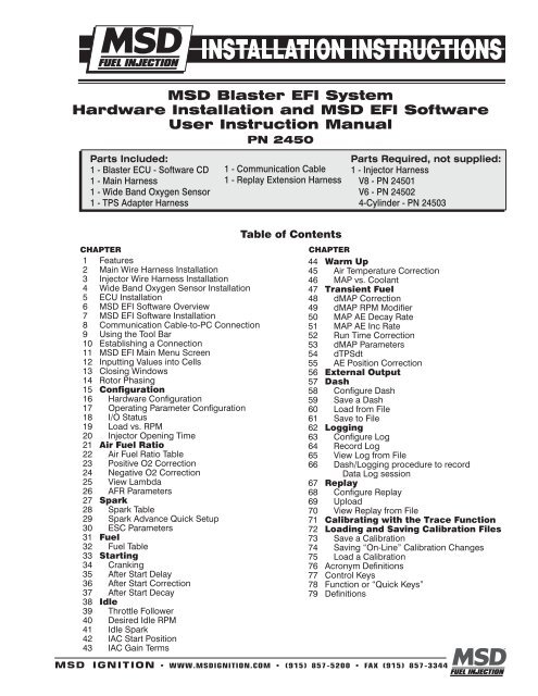
<strong>MSD</strong> <strong>Blaster</strong> <strong>EFI</strong> <strong>System</strong><strong>Hardware</strong> <strong>Installation</strong> <strong>and</strong> <strong>MSD</strong> <strong>EFI</strong> SoftwareUser Instruction ManualPN 2450Parts Included:1 - <strong>Blaster</strong> ECU - Software CD1 - Main Harness1 - Wide B<strong>and</strong> Oxygen Sensor1 - TPS Adapter Harness1 - Communication Cable1 - Replay Extension HarnessParts Required, not supplied:1 - Injector HarnessV8 - PN 24501V6 - PN 245024-Cylinder - PN 24503CHAPTER1 Features2 Main Wire Harness <strong>Installation</strong>3 Injector Wire Harness <strong>Installation</strong>4 Wide B<strong>and</strong> Oxygen Sensor <strong>Installation</strong>5 ECU <strong>Installation</strong>6 <strong>MSD</strong> <strong>EFI</strong> Software Overview7 <strong>MSD</strong> <strong>EFI</strong> Software <strong>Installation</strong>8 Communication Cable-to-PC Connection9 Using the Tool Bar10 Establishing a Connection11 <strong>MSD</strong> <strong>EFI</strong> Main Menu Screen12 Inputting Values into Cells13 Closing Windows14 Rotor Phasing15 Configuration16 <strong>Hardware</strong> Configuration17 Operating Parameter Configuration18 I/O Status19 Load vs. RPM20 Injector Opening Time21 Air Fuel Ratio22 Air Fuel Ratio Table23 Positive O2 Correction24 Negative O2 Correction25 View Lambda26 AFR Parameters27 Spark28 Spark Table29 Spark Advance Quick Setup30 ESC Parameters31 Fuel32 Fuel Table33 Starting34 Cranking35 After Start Delay36 After Start Correction37 After Start Decay38 Idle39 Throttle Follower40 Desired Idle RPM41 Idle Spark42 IAC Start Position43 IAC Gain TermsTable of ContentsCHAPTER44 Warm Up45 Air Temperature Correction46 MAP vs. Coolant47 Transient Fuel48 dMAP Correction49 dMAP RPM Modifier50 MAP AE Decay Rate51 MAP AE Inc Rate52 Run Time Correction53 dMAP Parameters54 dTPSdt55 AE Position Correction56 External Output57 Dash58 Configure Dash59 Save a Dash60 Load from File61 Save to File62 Logging63 Configure Log64 Record Log65 View Log from File66 Dash/Logging procedure to recordData Log session67 Replay68 Configure Replay69 Upload70 View Replay from File71 Calibrating with the Trace Function72 Loading <strong>and</strong> Saving Calibration Files73 Save a Calibration74 Saving “On-Line” Calibration Changes75 Load a Calibration76 Acronym Definitions77 Control Keys78 Function or “Quick Keys”79 Definitions<strong>MSD</strong> IGNITION • www.msdignition.com • (915) 857-5200 • FAX (915) 857-3344
INSTALLATION INSTRUCTIONS1 <strong>Blaster</strong> <strong>EFI</strong> <strong>System</strong> St<strong>and</strong>ard Features• Configurable Load & RPM axes to enable optimization in desired operating range• Capable of driving 8 high impedance injectors• “Wide B<strong>and</strong> Oxygen Sensor” (WB02) Air/Fuel Ration (AFR) control to eliminate base engine <strong>and</strong> transientfuel calibration guesswork.• Ignition system type is software configurable for GM HEI, Ford TFI, LT1 <strong>and</strong> Mag Pickup.• 1, 2, 3, 4, BAR MAP sensor compatible• Programmable injector opening vs. battery voltage• Improved transient fueling algorithms• Seamless decel fuel cut-off• Improved cold starting <strong>and</strong> drivability• The Throttle Position Sensor voltage output is linearized between .5V <strong>and</strong> 4.5V for GM <strong>and</strong> .9V to 4.5Vfor Ford.• Low side fuel pump <strong>and</strong> engine cooling fan functionality, as well as ESC control• Closed Loop PID WB02 heater control to insure accurate <strong>and</strong> consistent AFR control• Improved EMI algorithms• True Speed-Density algorithm allows for easier tuning• <strong>MSD</strong>Comm Windows 95, 98, 2000, NT <strong>and</strong> XP compatible calibration software• Electronics rated from -40° C to 105° C• Aesthetically pleasing, nylon braided wire harnesses with integrated ECU <strong>and</strong> Injector/WB02 fuseprotection.• OEM style Packard <strong>and</strong> TYCO waterproof connectors <strong>and</strong> terminals.2 Main Wire Harness <strong>Installation</strong>To improve the overall wire harness installation process, the harness was manufactured with identificationlabels at the end of each wire or connector to ensure that connections are terminated correctly. The mainwire harness has two halves; one half is intended to be located inside the vehicle, with the ECU, the otherhalf connects to the sensors in the engine compartment. The two halves of the harness are separated bya firewall grommet designed to fit snuggly in a 2-1/8” hole, which needs to be located in the firewall.The best location for the firewall hole is in an unobstructed location, on either side of the engine closest towhere the ECU will be mounted in the passenger compartment. Care should be taken to keep the harnessas close to the center of the vehicle as possible. Locating the hole too far away from the vehicle center mayaffect wire lengths, which need to connect to sensors on the engine. Once the main harness is installed theconnections need to be made to sensors, the ECU, etc. The paragraphs below describe how <strong>and</strong> whereeach connection should be made.The instructions on following page are specific to the <strong>Blaster</strong> engine management system. See page 71for a main harness wiring diagram.Note: Additional components such as relays <strong>and</strong> special connectors may be required to complete yourspecific installation.<strong>MSD</strong> IGNITION • www.msdFUELINJECTION.com • (915) 857-5200 • FAX (915) 857-3344
INSTALLATION INSTRUCTIONSHarness LabelESCWire Color/Connector TypeSingle lead PackardConnector with singlePurple wire.LabelDefinitionElectronic knock controlconnectionConnect ToA GM style engine knocksensor module.Further DetailsIf a knock sensor input will notbe used, do not connect thiswire. Only compatible withBank-to-Bank <strong>System</strong>s.HS GM FP Single lead with a single High Side Drive Connect to the positive sidered <strong>and</strong> Green stripedof the fuel pump relay.wire.FanPoints Single White wire. Output to <strong>MSD</strong> Ignition Only to an inductive pickupignition system.12v SwitchBattery (2connections)HEIH2OAirIACSwitched 12v supplyinputPositive <strong>and</strong> NegativeBattery connectionsHigh Energy Ignition[Original Equipment (OE)ignition]Engine Cooling FluidTemperature InputEngine Intake AirTemperature InputIdle Air Speed Control(IAC) inputConnect to a 12v sourcethat is “live” when theignition key is in the “start”position.The vehicle battery only!Connect to GM factoryinstalled ignition systemor appropriate adapterharness.Connect to the coolanttemperature sensor,typically located on theintake manifold.Connect to the airtemperature sensor typicallylocated in the air intake ductbetween the air cleaner <strong>and</strong>the throttle body.Connect to the AIC motorassembly located on ornear the throttle body.TPS Black, 3-way Packard Throttle Position Sensor The TPS located at the endconnector.of the throttle shaft on thethrottle body.CrankMAPMain Fuse <strong>and</strong>RelayInjector HarnessSingle lead Black/Whitewire.Single Pink wire.Two (2) 3/8” ringterminals. One (1) RedWire <strong>and</strong> one (1) blackwire terminas.Black, 4-way Ampconnector.Black, 2-way Packardconnector.Gray, 2-way Packardconnector.Black, 4-way Packardconnector.Black, 2-way connectorwith a separate groundwire (3/8” ring).Green, 3-way Packardconnector.Black, 4-way Packardconnector.Engine cooling fanconnectionCrankshaft positionsensor inputManifold AbsolutePressure SensorN/A N/A N/AInjector harnessconnectorConnect to the negativeside of the cooling fan relay.Connect to <strong>MSD</strong> Distributoror crank trigger.Connect to the MAP sensor.Connect to main wireharness.Do not connect this wiredirectly to the fuel pump. Arelay must be used.Do not connect this wiredirectly to the fan or positiveside of the relay. A relay mustbe used.Points.Switched Ignition.Battery ConnectionsCoolant Temperature.Air Temperature.Meters <strong>and</strong> controls intake airaround the throttle blades atidle <strong>and</strong> during cold starts.Senses the position of thethrottle blades [0% (throttleclosed) to 100 (throttle wideopen)]. TPS.MAP.Main Fues <strong>and</strong> Relay.Injector Harness.<strong>MSD</strong> IGNITION • www.msdignition.com • (915) 857-5200 • FAX (915) 857-3344
INSTALLATION INSTRUCTIONSThe paragraphs below further support the information outlined in the table above.Stage 1 (External Output) - Single red/orange wire.Provides 12 volts when external output is activated. The current limit on this circuit is 1 amp. Ifthe device used draws more current, a relay will have to be wired into the circuit.Injector - Four pin square connectorPlugs into the mating connector of the injector harness.Wideb<strong>and</strong> O2 - Six pin rectangular connectorConnects to the oxygen sensor.Toss - Two pin black connectorPlugs into the speed sensor on GM 4L80E transmissions.ESC (Electronic Spark Control) – Single lead Packard connector with Purple wire.This wire connects to the GM type ESC module. The module is usually located on the fender or firewall.The knock sensor is not required if high-octane fuel is being used.Fuel Pump (HS) - Single Red/Green striped wire.This connector must go to the positive side of a fuel pump relay, notdirectly to the fuel pump. Terminating this connection directly toa fuel pump will damage the <strong>Blaster</strong> controller <strong>and</strong> will void thewarranty! The fuel pump relay <strong>and</strong> wiring provisions are not suppliedwith the system.Fan (engine cooling fan) - Single Black/White wireThis termination must go to the negative side of a fan relay, not directlyto the fan. Terminating this connection directly to a fan will damagethe <strong>Blaster</strong> controller <strong>and</strong> will void the warranty!FUELFUEL PUMPFROMECUH20FANPoints - Single White wireDo not connect this wire if a factory ignition system is being used.This is the <strong>Blaster</strong> ECM’s “points” signal (White wire). It needs to beconnected to the “points” input connection on an aftermarket ignitionmodule, e.g. <strong>MSD</strong> 7A box.12V Switched - Single Pink wireA secure connection must be made to a switched 12V supply. The best<strong>and</strong>, in most cases, the only source of a switched 12V supply is at the vehicle fuse block. The ECU musthave a “live” 12V supply during cranking. If the 12V supply does not stay live during cranking the ECUwill not function. A simple way to determine if a live 12V supply exists during cranking is to check it withan inexpensive voltmeter. Securely fasten the voltmeter’s Red (+ positive) wire to the ignition input on thefuse block. Secure the voltmeter’s Black wire (- negative) to a ground location on the fuse block or anotheradequate location. Once the voltmeter connections are made, crank the engine. The voltage meter shouldindicate an output voltage of between 8V to 14V. If the output voltage is below 8 volts, check to make surethe battery is fully charged <strong>and</strong> all the cells of the battery are functioning properly.Positive <strong>and</strong> Negative Battery Connections - Two (2) 3/8” ring terminals, One (1) Red wire terminal<strong>and</strong> One (1) Black wire terminalThe main wire harness battery connections need to be made to the positive <strong>and</strong> negativeposts of the vehicle battery to ensure trouble free operation! The positive <strong>and</strong> netagive betterycable lengths have been designed with sufficient length to accommodate a trunk-mounted battery. Makesure the Black wire battery (-) is securely fastened to the negative battery post (NO EXCEPTIONS). TheRed cable battery (+) must be securely fastened to the positive (+) battery post. Reversing the batteryconnections will damage the ECU <strong>and</strong> void the warranty!FANFROMECU87A - Normally Closed87 - Normally Open30 - Common<strong>MSD</strong> IGNITION • www.msdFUELINJECTION.com • (915) 857-5200 • FAX (915) 857-3344
INSTALLATION INSTRUCTIONSMaking battery connections to locations on the vehicle other than the battery itself can cause the ECU tofunction improperly, due to potential ground loop issues. Connect these wires to the battery only after allother connections are made.Factory Dist - Black, 4-way AMP connectorThe main harness Factory Dist connection plugs directly into an <strong>MSD</strong> LT1 distributor. If using a factoryLT1 distributor, external coil HEI, or Ford TFI distributor an adapter harness will have to be purchased.Appropriate harnesses are listed below:TFI Adapter . . . . . . . . . . . . . PN 24505External Coil HEI Adapter . . PN 24507’92-’95 LT1 Adapter . . . . . . PN 24508’96-’97 LT1 Adapter . . . . . . PN 24509The jumper cable needs to be installed between the Main wire harness <strong>and</strong> the distributor being used inthe vehicle. This connection also includes a “bypass” connector for setting the timing.H20 - Black, 2-way Packard connectorThis connector mates with a GM style coolant temperature sensor.Air - Gray, 2-way Packard connectorThis connector mates with a GM style air temperature sensor.IAC (Idle/Air Control) - Black, 4-way Packard connectorThe main harness IAC connector was designed to work with a GM style IAC motor <strong>and</strong> valve assemblywith a 4 by 1 connector. This is the IAC used on <strong>MSD</strong> Throttle Body PN 2250. If a GM style IAC motor <strong>and</strong>valve assembly with a 2 by 2 in-line connector is used, an adapter harness will need to be purchased (<strong>MSD</strong>PN 24510). The Adapter harness needs to be installed between the Main wire harness <strong>and</strong> the in-line IACvalve <strong>and</strong> motor assembly.Alternatively, the factory installed 4 by 1 connector can be removed <strong>and</strong> replaced with a 2 by 2 in-lineconnector per the pin-out table below.2 by 2 IAC Connector Pin-out Identifier 4 by 1 In-line IAC Connector Pin-out IdentifierADBCCBDATPS (Throttle Position Sensor) - Black, 3-way Packard connectorThe main harness TPS connector was designed to work with a GM “L98” style TPS with a 3 by 1connector.If a late model GM TPS with a 3-pin round connector is used the supplied adapter harness will have to beused. If a Ford TPS will be used the factory connector will have to be replaced.Alternatively, the factory installed TPS connector can be removed <strong>and</strong> replaced with a late model GM orFord TPS connector per the pin-out tables below.GM Late Model3 by 1 TPS Connector Pin-out IdentifierABCGM Late Model Round, “3-point” TPSConnector Pin-Out IdentifierBCA<strong>MSD</strong> IGNITION • www.msdignition.com • (915) 857-5200 • FAX (915) 857-3344
INSTALLATION INSTRUCTIONSFord TPS3 by 1 TPS Connector Pin-out Identifier Ford TPS Connector Pin-Out IdentifierACBBCAMag Pickup - Black, 2-way connector with a separate ground wire (3/8” ring)The black connector should be connected to an <strong>MSD</strong> distributor or crank trigger. The Black wire ringterminal should be securely fastened to the engine block.MAP (Manifold Absolute Pressure) - Green, 3-way Packard connectorConnect to a GM style (1 BAR) Manifold Absolute Pressure (MAP) sensor. For normally aspirated engines,a 1 bar sensor is used. For blown or turbocharged applications a 2 BAR MAP sensor must be used forboost pressures up to 15 PSI. For boost pressures up to 30 PSI a 3 BAR MAP sensor must be used. Forboost pressures up to 45 PSI a 4-BAR MAP sensor must be used. If a 2 or 3 BAR MAP sensor is required,it must be obtained from <strong>MSD</strong> or the connector will have to be changed.1 BAR . . . . . . . . . . . . . . .PN 231112 BAR . . . . . . . . . . . . . . .PN 231213 BAR . . . . . . . . . . . . . . .PN 231314 BAR . . . . . . . . . . . . . . .Call for details.For speed-density applications, the MAP sensor must be connected to an intake manifold port. For Alpha/Nsystems, use the sensor to sense ambient air pressure in the hood scoop or air cleaner.ECU 3-Amp FuseThis fuse protects the ECU electronics.30-Amp FuseThis fuse protects the wide b<strong>and</strong> oxygen sensor circuit.Replay (Internal Dat Logger) - Black, 2-way connector with blue <strong>and</strong> black wires. This pigtail comesout of the ECU.When the black <strong>and</strong> blue wires are connected together the internal data logger is armed. A switch <strong>and</strong>extension harness is provided in the kit.3 Injector Harness <strong>Installation</strong> - Black, 4-way Packard connectorOnce the main harness is installed <strong>and</strong> all the connections to it are made, the injector harness can beinstalled <strong>and</strong> connected to the main harness.The injector harness is constructed with the connector (for the connection to the main wire harness)located half way between the two banks of fuel injector connectors. The main-harness-to-injector harnessconnection should be made on the end of the engine opposite the ignition distributor. For example, forGM engines, the main harness to injector harness connection should be made at the front of the engine.For a Ford 5.0L engine, the connection should be made at the back of the engine.4 Wide B<strong>and</strong> Oxygen Sensor <strong>Installation</strong>Once the main <strong>and</strong> injector harnesses are installed, the Wide B<strong>and</strong> Oxygen (WBO2) sensor needs to beinstalled <strong>and</strong> connected to the main harness. First, install the wide b<strong>and</strong> sensor.The WBO2 sensor threads into the sensor mounting bung (<strong>MSD</strong> PN 2335), which needs to be drilled <strong>and</strong>welded into the exhaust pipe. Before drilling <strong>and</strong> welding, read the design guidlines below.• Install the mounting bung approximately 8” - 12” from where the primary pipes enter the exhaust collector.• Make sure the mounting location selected does not allow condensation to collect directly in front of the sensor.Make sure there are no depressions, projections, edges, etc. in the exhaust pipe near the sensor tip.<strong>MSD</strong> IGNITION • www.msdFUELINJECTION.com • (915) 857-5200 • FAX (915) 857-3344
INSTALLATION INSTRUCTIONS• The mounting angle of the sensor should be tilted a minimum of 10° to the horizontal tip of the sensor.The tip of the sensor must be tilted down. See the diagram below. The optimum sensor angle is 90°.• Make sure sensor cabling is routed <strong>and</strong> secured away from the exhaust system.OXYGEN SENSORMOUNTING BUNG(ENTIRE CIRCUMFERENCETHE OPTIMALNEEDS TO BE WELDED)ANGLE ISCOMPLETELYVERTICAL OR90 OOXYGEN SENSOR10 0 ANGLE MINIMUMEXHAUST PIPEDrill a 7/8” - 15/16” hole in the exhaust pipe. Weld a WBO2 sensor-mounting bung into the exhaust pipe. Themounting bung was manufactured with a lip to help locate it prior to welding it to the exhaust pipe. The entirecircumference of the mounting bung must be welded <strong>and</strong> free of exhaust leaks!Once the sensor-mounting bung is welded into place, thread the sensor into the bung. <strong>Installation</strong> torque isabout 10 - 15 ft/lbs. Connect the oxygen sensor 6-way connector (with gold plated terminals) to the main wireharness.5 ECU <strong>Installation</strong>Note: The ECU MUST be installed in the passenger compartment! The ECU has four vibration mounts thatattach to the bottom of the housing. Once installed, connect the main wire harness header connector tothe ECU.The <strong>Blaster</strong> system hardware installation process is now complete.The next step is to install the <strong>MSD</strong> <strong>EFI</strong> software,which allows the sensor interfaces to be checked, <strong>and</strong> ultimately start <strong>and</strong> operate the engine.The remainder of the manual will describe how to install <strong>and</strong> use the <strong>MSD</strong> <strong>EFI</strong> software to monitor <strong>and</strong> calibratethe <strong>Blaster</strong> ECU parameters <strong>and</strong> variables.6 <strong>MSD</strong> <strong>EFI</strong> Software OverviewThe <strong>Blaster</strong> system can be configured to operate on almost any 4-cylinder, V6 or V8 engine, including normallyaspirated, supercharged <strong>and</strong> turbocharged applications! The <strong>MSD</strong> <strong>EFI</strong> software was designed to act as theinterface between the <strong>Blaster</strong> ECU <strong>and</strong> the engine it is installed on. View it as the screwdrivers <strong>and</strong> wrenchesonce used to make crude adjustments to a carburetor. The <strong>MSD</strong> <strong>EFI</strong> software allows the user extraordinaryability to tune the fuel <strong>and</strong> ignition system for improved performance <strong>and</strong> drivability.The <strong>MSD</strong> <strong>EFI</strong> software allows full user access to all of the tables needed to calibrate the <strong>Blaster</strong> system. Calibrationscan be modified both “on-line” <strong>and</strong> “off-line”. The engine control tables in the <strong>MSD</strong> <strong>EFI</strong> ECU are stored in nonvolatilememory, allowing for the stored information not to be lost when power to the ECU is removed.The minimum computer requirements to run the <strong>MSD</strong> <strong>EFI</strong> software are:• Microsoft Windows 95/98/Me/2000/NT or XP• 300 MHz or faster Pentium processor.<strong>MSD</strong> IGNITION • www.msdignition.com • (915) 857-5200 • FAX (915) 857-3344
INSTALLATION INSTRUCTIONS• <strong>Blaster</strong> recommends a minimum of 128K of RAM.• RS-232 serial port recommended. A USB port can also be used with a port adapter (not included).7 <strong>MSD</strong> <strong>EFI</strong> Software <strong>Installation</strong>1. Insert the installation CD Rom into the CD Drive, wait up to 30 seconds, the CD will auto run. IF THIS DOESNOT OCCUR:Locate <strong>and</strong> open the CD Drive.Double click on the autorun.exe file.2. Select “Click here to install Version X.XX”.3. Once loaded, your monitor will have an <strong>MSD</strong> <strong>EFI</strong> logo. Accept the agreement. Drive the installation to yourprogram files folder, press the enter key. The installation will complete, select OK.4. A window will be opened with two aliases, double click on the <strong>MSD</strong> <strong>EFI</strong> alias to launch the software.8 Communication Cable-to-PC ConnectionUsing the communication cable supplied with the system connect the RS-232 connector to the back of thepersonal computer.Port ProblemsIf the PC is a newer model it will most likely have a USB port. If the PC being used is an older model it may onlyhave a 25-pin serial port. Make sure the 25-pin port, on the back of the PC, is a serial port <strong>and</strong> not a parallel port,there is a difference. The parallel port will not work. Parallel ports are typically printer ports that let data travelin only one direction. If your PC is configured with only a USB port, a USB-to-9-pin adapter must be procured.USB-to-9-pin or 25-pin-to-9-pin serial adapters are readily available at Radio Shack or comparable stores. RadioShack’s USB port to 9-pin serial adapter is part number 26-183 <strong>and</strong> available for approximately $40.00.Prior to establishing communication with the <strong>Blaster</strong> ECU, the PC’s COM port needs to be selected. In orderto complete the PC COM port selection a quick overview of the Tool Bar is required. The configuration tableswithin the <strong>MSD</strong> <strong>EFI</strong> software area accessed using the <strong>MSD</strong> <strong>EFI</strong> Tool Bar explained on following page.<strong>MSD</strong> IGNITION • www.msdFUELINJECTION.com • (915) 857-5200 • FAX (915) 857-3344
INSTALLATION INSTRUCTIONS9 Using the Tool BarThe Tool Bar is located at the very top of the <strong>MSD</strong> <strong>EFI</strong> Main Menu screen. All of the <strong>MSD</strong> <strong>EFI</strong> software functionalityis accessed using the Tool Bar <strong>and</strong> associated drop down screens.If the Com Port selectedis not available, thefollowing message willappear.<strong>MSD</strong> IGNITION • www.msdignition.com • (915) 857-5200 • FAX (915) 857-3344
INSTALLATION INSTRUCTIONS 11Left mouse click the Work Offline button. The <strong>MSD</strong> <strong>EFI</strong> software will ask what calibration should be used “off-line”.The following screen will appear, informing the user that a calibration file must be loaded to work “off-line”.Left mouse click on Yes <strong>and</strong> the <strong>MSD</strong> <strong>EFI</strong> software should go to the <strong>MSD</strong> <strong>EFI</strong> folder. If the PC does not automaticallytake you to the <strong>MSD</strong> <strong>EFI</strong> folder, navigate to C:/ Program Files/<strong>MSD</strong>_<strong>EFI</strong>. Double left click on the calibration tobe used for “off-line” modifications <strong>and</strong> the calibration will be loaded. After the calibration is loaded, the Main<strong>MSD</strong> <strong>EFI</strong> window will open.<strong>MSD</strong> IGNITION • www.msdignition.com • (915) 857-5200 • FAX (915) 857-3344
INSTALLATION INSTRUCTIONS 13Once communication has been established, the <strong>MSD</strong> <strong>EFI</strong> “Main Menu” screen will open <strong>and</strong> the Green SlidingBall in the tool bar will become active.11 <strong>MSD</strong> <strong>EFI</strong> Main Menu ScreenThe engine is not yet ready to be started. A few additional items need to be completed before attemptingto do so!In most cases, the ECU will be delivered with a calibration that will closely match your engine configuration. This“base calibration” will allow the engine to be started <strong>and</strong> run. If this is not the case, the following steps need tobe taken.Note: <strong>MSD</strong> recommends checking all of the settings in the configuration tables to ensure the system as suppliedwill operate correctly.12 Inputting Values into a CellThere are two methods for inputting values into cells as follows:• Arrow Keys - Use the PC keyboard arrow keys to navigate the cursor horizontally <strong>and</strong>/or vertically to the cellto be changed. Input the desired value <strong>and</strong> hit “Enter”.• Using the Mouse - Use the Mouse to navigate the cursor to the cell to be changed <strong>and</strong> left Mouse click onthe cell. Input the desired value <strong>and</strong> hit “Enter” to save the change.13 Closing WindowsOpen windows can be closed using the PC’s mouse. To close an open window, left mouse click on the “X”in the upper right corner of any window <strong>and</strong> it will close. Another method to close open windows, tables <strong>and</strong>drop down screens is to hit the PC’s escape key, typically abbreviated as “Esc”. If multiple windows are open,continue to hit the Esc key until all windows are closed <strong>and</strong> the main <strong>MSD</strong> <strong>EFI</strong> window is displayed. Hitting theEsc key too many times may result in a message stating, “Do you really want to quit?” Hit “No” to continueworking with the <strong>MSD</strong> <strong>EFI</strong> software. Hit “Yes” to close the <strong>MSD</strong> <strong>EFI</strong> software.<strong>MSD</strong> IGNITION • www.msdignition.com • (915) 857-5200 • FAX (915) 857-3344
18 INSTALLATION INSTRUCTIONSCrank Trigger ConfigurationSee settings below for the input values [Crank Ref Angle (deg) <strong>and</strong> Inductive Delay (µs)] to be used, based onthe most common configurations.The crank timing (Crank Ref Angle) should equal the value in the table.Engine Type Crank Ref Angle Inductive Delay (µ seconds)LT1 6° 6Ford TFI 10° 0GM HEI 6° 64IPU 45° 77Engine Cooling Fan Control ConfigurationThis input screen allows the user to set the coolant temperature that the <strong>Blaster</strong> ECU will turn the engine-coolingfan on (Fan On Temp) <strong>and</strong> off (Fan Off Temp). The Fan Off temperature should be ~ 5° to 10° less than the FanOn temperature.Fuel Pump ConfigurationThis input screen allows the user to set the amount of time the fuel pump will run when the ignition is turnedto the “On” position. This allows the user time to prime the fuel pump <strong>and</strong> check for leaks before the engine isstarted. A time period of up to 25 seconds can be specified on this screen.Drivetrain ConfigurationThe vehicle final drive ratio <strong>and</strong> tire diameter inputs are required to enable the ECU to make the correct Mile-Per-Hour (MPH) calculations.Pickup WheelsThis input screen allows the user to set the quantity of teeth on the transmission output shaft. This input is partof the MPH calculation made by the ECU. For reference, the GM 4L60E <strong>and</strong> 4L80E transmissions have 40 teethtone rings on their output shafts.19 Load vs. RPMThe <strong>Blaster</strong> <strong>MSD</strong> <strong>EFI</strong> system offersconfigurable Load <strong>and</strong> RPM axes.This feature allows the user to configurethe X axis (RPM) <strong>and</strong> Y Axis(Load), so that a majority of the available16 cell by 16 cell fuel <strong>and</strong> sparkmap area is available for calibrating.<strong>System</strong>s with fixed X <strong>and</strong> Y axis allowonly a small portion of the availablemap area to be used to calibrate thefuel <strong>and</strong> spark needs of the engine.This capability is extremely importantif the engine is fuel or spark sensitiveat a given load <strong>and</strong>/or RPM. For example,if the engine/transmission/reargear combination makes the enginesensitive to throttle changes at 2,200RPM, the user can configure the X-axis in 200 or 300 RPM incrementsat or around 2,200 RPM.<strong>MSD</strong> IGNITION • www.msdFUELINJECTION.com • (915) 857-5200 • FAX (915) 857-3344
INSTALLATION INSTRUCTIONS 19If the “Speed Density” control algorithm was selected during the aforementioned <strong>Hardware</strong> Configuration step,the screen should show MAP (kPa) in the Y axis <strong>and</strong> RPM in the X axes. If the screen shows TPS % <strong>and</strong> thepreferred control algorithm is “Speed Density,” go back to Main Configuration <strong>and</strong> select Seed Density insteadof Alpha N.20 Injector Opening TimeNext, go back to Configuration on the Tool Bar. Left click on the “Configuration” <strong>and</strong> the drop down screen willopen. Keep the left mouse button depressed <strong>and</strong> slide the mouse pointer down until “Injector Opening Time”is highlighted. Release the left mouse button. The screen below will open.The purpose of this table is to allow the user to configure the ECU to maintain a constant injector flow rate withvarying battery voltages.Fuel injectors have a minimum pulsewidth (in milliseconds) required beforethey will open <strong>and</strong> let fuel flow. Forexample, with a constant batteryvoltage of 13.4V, a 60 lb/hr. Boschinjector is not likely to open until theECU sends a pulse width comm<strong>and</strong>of 1.4 to 1.5 milliseconds (injectoropening time is also influenced by fuelpressure).<strong>MSD</strong> IGNITION • www.msdignition.com • (915) 857-5200 • FAX (915) 857-3344
20 INSTALLATION INSTRUCTIONS21 Air Fuel Ratio (F11)At a given voltage, the minimum pulse width required to open an injector will vary based on injector size, injectortype <strong>and</strong> manufacturer. This input screen allows the user the ability to fine tune flow rates (injector opening time)based on battery voltage.The following sections of the manual will outline how to use the Air/Fuel Ration table, O2 Correction tables <strong>and</strong>the Fuel Table. Calibrating the engine for steady state operation is an iterative process using these tables.The fuel calibration process, in order of importance, is as follows:• The air/fuel ration table will be configured to desired ratios for the different engine speed <strong>and</strong> loadcombinations.• The positive <strong>and</strong> negative O2 correction tables will be configured.• The volumetric efficiency (VE) values in the Fuel Table will be calibrated.Once these tables are configured, as a baseline, the Calibrating with the Trace Function can be used to finetunethe interrelationships of the aforementioned tables. The “Trace” function allows the engine to be quicklycalibrated “On-Line” (ECU powered up) or “Off-Line” (PC only). The Trace Function is explained in Chapter 71of this manual.22 Air Fuel Ratio TableNote: In most cases, the ECU shipped with your system will come pre-configured with a table,which will closely match your engine configuration. The air fuel ratio table below allows theuser to input desired air/fuel ratios for sixteen (16) engine speed (RPM) <strong>and</strong> 8 load (MAP orTPS) combinations. The X-axis represents engine RPM <strong>and</strong> allows for 16 inputs <strong>and</strong> the Y-axisrepresents engine load <strong>and</strong> allows for 8 inputs. For each speed <strong>and</strong> load combination (cell) the engineoperates within, the ECU uses the WB92 sensor feedback to achieve the desired air/fuel ratio for thatcell.While the engine is running, a “Real-Time Ellipse” will move throughout the Air Fuel Ratio table relative to the currentRPM <strong>and</strong> Load “operating point”. Use it as a point of reference to help calibrate the Air Fuel Ratio table.To change a cell value in th Air Fuel Ratio table, move the cursor using the PC’s mouse or the arrow keys to thecell to be changed. Click on the cell <strong>and</strong> type a desired Air Fuel Ratio value (from 10.5 to 15.0) <strong>and</strong> hit “Enter”to save the change.<strong>MSD</strong> IGNITION • www.msdFUELINJECTION.com • (915) 857-5200 • FAX (915) 857-3344
INSTALLATION INSTRUCTIONS 21To make changes to multiple cells simultaneously, left mouse click <strong>and</strong> drag the cursor (down <strong>and</strong> to the right)across the cell range to be changed. Release the left mouse button <strong>and</strong> a secondary drop down screen willappear outlining three potential “cell fill” options.• Fill - Choosing “Fill” will open a secondary drop down-screen which allows the selected cells to be changedto the value inputted into the window.• Multiply - Choosing “Multiply” will open a secondary drop down-screen which allows the values of theselected cells to be changed by the “Multiply” value inputted into the window. For example, if the valuesin the cells selected are 13 <strong>and</strong> the inputted “Multiply” value was 80, the new cell values would be 10.4.• Interpolate - If a series of cells in the same row are selected <strong>and</strong> the “Interpolate” “cell-fill” option is selectedthe ECU will use the value in the cell all the way to the left <strong>and</strong> the cell value all the way to the right <strong>and</strong>interpolate the numbers in between so that the values are linear.EXAMPLE:Cell values Selected in a Row14 14 13.5 13.8Interpolated Results from Cell Values Selected Above14 13.9 13.8 13.8If a series of cells in the same column are selected <strong>and</strong> the “Interpolate” option is selected the ECU will use thevalue in the cell all the way at the bottom <strong>and</strong> the cell value all the way at the top <strong>and</strong> interpolate the numbersin between so that the values are linear.EXAMPLE:Cell Values Selected in a Column13131413.9Interpolated Results from Cell Values Selected Above1313.313.613.9<strong>MSD</strong> IGNITION • www.msdignition.com • (915) 857-5200 • FAX (915) 857-3344
22 INSTALLATION INSTRUCTIONSIf a range of cells (multiple rows <strong>and</strong> columns) are selected <strong>and</strong> the “Interpolate” “cell-fill” option is selected theECU will use the value in the cells at the bottom left <strong>and</strong> top left corners, bottom left <strong>and</strong> bottom right corners<strong>and</strong> the bottom left <strong>and</strong> top right corners of the entire range <strong>and</strong> interpolate the numbers in between so thatthe values are linear.EXAMPLE:Range of Cell Values Selected13 13 13 1313.8 13.8 13.8 13.814.1 14.1 14 1414 14.2 14.2 14Interpolated Results from Range of Cell Values Selected Above13 13 13 1313.3 13.3 13.3 13.313.6 13.6 13.6 13.614 14 14 14• Cancel - Hit cancel to disregard making any changes.Example Air Fuel Ratio TablesExample air fuel ratio tables, for a normally aspirated street engine, a supercharged engine <strong>and</strong> a turbochargedengine, are shown below. The air/fuel ratio values in these cells can be used as base lines for each of the engineconfigurations. The “Example Maps” below are segmented into engine operating areas (Cruise, Idle, Wide OpenThrottle, etc.) to help the user underst<strong>and</strong> what part of the map is “active” under different driving conditions(engine speed <strong>and</strong> load combinations).Normally Aspirated Street Engine<strong>MSD</strong> IGNITION • www.msdFUELINJECTION.com • (915) 857-5200 • FAX (915) 857-3344
INSTALLATION INSTRUCTIONS 23Turbocharged Engine (30 PSI)Super Charged Engine (15 PSI)23 Positive O2 CorrectionThe air fuel ratio table at right allows theuser to specify desired air/fuel ratios for128 speed <strong>and</strong> load combinations. Thepositive <strong>and</strong> negative O2 correctiontables on next page allow the user tospecify how much fuel the O2 Correctionwill be allowed to add or subtract toachieve the user defined air/fuel ratio.The positive <strong>and</strong> negative O2 Correctiontables limit the amount added orsubtracted.The eight (8) horizontal input cells inthe tables correspond to the eight (8)vertical “Load” rows in the Air/Fuel RatioTable. The input values in the tables addor subtract fuel, as a percentage, for eachcell in the entire engine “Load” row. Thecell all the way to the left corresponds tothe bottom row in the air/fuel ratio table<strong>and</strong> the cell all the way to the right corresponds to the top row of the air/fuel ratio table.<strong>MSD</strong> IGNITION • www.msdignition.com • (915) 857-5200 • FAX (915) 857-3344
24 INSTALLATION INSTRUCTIONSTo make changes to the values in these tables, use the left or right arrow keys to move the cursor to the cell tobe changed. Input the desired value <strong>and</strong> hit “Enter”.24 Negative O2 CorrectionThis table is configured <strong>and</strong> operates in the same way as the table above. The difference is that this table limitsthe amount of Negative O2 Correction.<strong>MSD</strong> IGNITION • www.msdFUELINJECTION.com • (915) 857-5200 • FAX (915) 857-3344
INSTALLATION INSTRUCTIONS 2525 View Lambda (F2)The View Lambda allows the user to view the current Lambda status in a large LED-like format.The window can be exp<strong>and</strong>ed or contracted by locating the mouse cursor at the edge of the window. The cursorwill change shape from an arrow with one (1) point, to an arrow with points on both ends. When the cursor isin the two-point mode, hold the left mouse button down <strong>and</strong> pull the edge of the window in or out to exp<strong>and</strong>or contract the window.26 AFR Parameters (F11)The Air/Fuel Ratio (AFR) Parameters table allows the user to configure control parameters associated with closedloop fuel control, using the WBO2 sensor.The following paragraphs will describe the function of each control parameter.RPM On Inputs• RPM On - Defines the RPM theengine needs to exceed beforethe ECU will allow the system togo into closed loop fuel using theO2 sensor.Minimum Coolant TemperatureThe minimum coolant temperatureinput is the temperature threshold theengine coolant needs to exceed beforethe ECU will let the system go intoclosed loop control.To make changes to the values inthese tables, use the left or right arrowkeys to move the cursor to the cell tobe changed. Input the desired value<strong>and</strong> click on “OK” at the bottom of thetable.<strong>MSD</strong> IGNITION • www.msdignition.com • (915) 857-5200 • FAX (915) 857-3344
26 INSTALLATION INSTRUCTIONS27 Spark (F4)There are several ways to access the base Spark table. The quickest methods are to hit the F4 “Quick Key”or left mouse click on the Spark Table icon, accessible from the main <strong>MSD</strong> <strong>EFI</strong> Screen. The Main Tool Bar canalso be used to access the Spark table. From the main <strong>MSD</strong> <strong>EFI</strong> software screen tool bar left click on Spark<strong>and</strong> the drop down screen will open.When the key is turned on the ECU takes a snapshot of the MAP sensor <strong>and</strong> records the atmosphericpressure (Barometer). The fuel <strong>and</strong> spark advance maps have a red line that is displayed horizontally acrossthe table. This line represents the Baro pressure. Baro will have different values based on the elevationthe vehicle is located at. MAP readings above the line represent positive manifold pressure (Boost) <strong>and</strong>values below represent negative manifold pressure (Vacuum). The scale on the right side of the tabledisplays boost in psi <strong>and</strong> vacuumin In-Hg. The variable “Baro” mustbe displayed in the fuel <strong>and</strong> sparkadvance windows dash for the lineto be displayed correctly. In orderto achieve a correct baro readingthe key should be turned on for atleast one second before crankingthe engine.28 Spark TableThe Spark table uses actualtiming values in each of the256 cells in the table. TheSpark table allows the user to inputSpark values for sixteen (16) enginespeed (RPM) <strong>and</strong> sixteen (16) load(MAP or TPS) combinations. TheX-axis represents engine RPM <strong>and</strong>allows for 16 inputs <strong>and</strong> the Y-axisrepresents engine load <strong>and</strong> allowsfor sixteen (16) inputs as well. TheX <strong>and</strong> Y-axes are configurable. Forinformation on how to configure the X<strong>and</strong> Y-axes see Load vs RPM.While the engine is running, a “Real-Time Ellipse” will move throughout theSpark table relative to the current RPM<strong>and</strong> Load “operating point”. Use it asa point of reference to help calibratethe Spark table.To change a cell value in the Spark<strong>MSD</strong> IGNITION • www.msdFUELINJECTION.com • (915) 857-5200 • FAX (915) 857-3344
INSTALLATION INSTRUCTIONS 27table, move the cursor using the PC’s mouse or the arrow keys to the cell to be changed. Click on the cell <strong>and</strong>type a desired Spark value (from 15.0 to 63.8) <strong>and</strong> hit “Enter” to save the change.To make changes to multiple cells simultaneously, left mouse click <strong>and</strong> drag the cursor across the cell rangeto be changed. Release the left mouse button <strong>and</strong> a secondary drop down screen will appear outlining threepotential “cell fill” options.• Fill - Choosing “Fill” will open asecondary drop down-screen whichallows the selected cells to bechanged to the value inputted intothe window.• Multiply - Choosing “Multiply” willopen a secondary drop downscreenwhich allows the values ofthe selected cells to be changed bythe “Multiply” value inputted into thewindow. For example, if the valuesin the cells selected are 13 <strong>and</strong> theinputted “Multiply” value was 80, thenew cell values would be 10.4.• Interpolate - If a series of cells inthe same row are selected <strong>and</strong>the “Interpolate” “cell-fill” option isselected the ECU will use the valuein the cell all the way to the left <strong>and</strong>the cell value all the way to theright <strong>and</strong> interpolate the numbersin between so that the values arelinear.Cell values Selected in a Row30.5 27.8 27.8 27.8Interpolated Results from Cell Values Selected Above30.5 29.5 28.5 27.8If a series of cells in the same column are selected <strong>and</strong> the “Interpolate” option is selected the ECU will use thevalue in the cell all the way at the bottom <strong>and</strong> the cell value all the way at the top <strong>and</strong> interpolate the numbersin between so that the values are linear.EXAMPLE:Cell Values Selected in a Column27.830.53233Interpolated Results from Cell Values Selected Above27.829.531.333<strong>MSD</strong> IGNITION • www.msdignition.com • (915) 857-5200 • FAX (915) 857-3344
28 INSTALLATION INSTRUCTIONSIf a range of cells (multiple rows <strong>and</strong> columns) are selected <strong>and</strong> the “Interpolate” “cell-fill” option is selected theECU will use the value in the cells at the bottom left <strong>and</strong> top left corners, bottom left <strong>and</strong> bottom right corners<strong>and</strong> the bottom left <strong>and</strong> top right corners of the entire range <strong>and</strong> interpolate the numbers in between so thatthe values are linear.EXAMPLE:Range of Cell Values Selected27 30.5 33.3 33.326 33.3 33.3 3422 28 34 3518 25 35 3615 22 33 35Interpolated Results from Range of Cell Values Selected Above27 29 31 33.324 27 30.3 33.521 25.3 29.8 3418 23.5 29 34.515 21.5 28.3 35• Cancel - Hit cancel to disregard making any changes.The illustration below shows the areas of the Spark map that the ECU accesses under different drivingconditions.Cell Changes using the “Page Up” <strong>and</strong> “Page Down” Keys (Fuel <strong>and</strong> Spark Tables)Multiple cell values can also be changed simultaneously using the “Page Up” <strong>and</strong> “Page Down” keys. Thisapproach offers a quick alternative to using the mouse. Use the keyboard arrow keys (up/down/left/right) tomaneuver to area of the map where the desired cell changes will be made. Next, depress <strong>and</strong> hold the keyboard“Shift” key. Depress the “Page Up” key to increase the cell values <strong>and</strong> the “Page Down” key to decrease thecell values. The cell values will increase or decrease by a value of one (1) for every keystroke. To exit this mode,depress any one of the arrow keys.The <strong>MSD</strong> <strong>EFI</strong> software allows the user to configure the Load(MAP) <strong>and</strong> RPM axes allowing for a larger number of cells(map area) to be used for the fuel <strong>and</strong> spark tables.<strong>MSD</strong> IGNITION • www.msdFUELINJECTION.com • (915) 857-5200 • FAX (915) 857-3344
INSTALLATION INSTRUCTIONS 2929 Spark Advance Quick SetupThis feature allows a timing curve to be built independent of engine load. A simple curve is entered whichis identical to the mechanical advance function of a distributor (minus vacuum advance). For those new tofuel injection who are un-familiar with a load-based spark map, it is suggested to begin using this option.The load-based values can be changed at a later time if desired. Once this mode is selected the SparkAdvance Quick Setup <strong>and</strong> Spark Advance Table windows will be displayed. Timing values are entered intothe 2D table. Any value entered into the 2D table will populate the entire column for that RPM in the SparkAdvance Table. For example: a value of 10 degrees is entered into the 1000 RPM cell, after the Enter keyis pressed the entire 1000 RPM column of the Spark Advance Table gets updated to 10 degrees.30 ESC ParametersNote: If “knock” sensors are not being used, no inputs are required in this table. The system is configuredto work with GM style “knock” sensors.ESC Configuration TableThe Electronic Spark Control (ESC) Configuration table allows the user to take timing out of the engine if the GMstyle knock sensor detects “knock,” or pre-ignition, in the engine. The table below has three input screens.• Knock Retard Rate - The amount of timing, in degrees per second, the ECU will take timing out if thesensor detects “knock”.• Knock Rate Restore - The rate, in degrees per second, in which timing is added back or restored once“knock” or longer present.• Max ESC - The maximum amount of timing the ECU will pull out if “knock” is detected.The values shown in the table below can be used as a base line starting point.<strong>MSD</strong> IGNITION • www.msdignition.com • (915) 857-5200 • FAX (915) 857-3344
30 INSTALLATION INSTRUCTIONS31 Fuel (F3)There are several ways to access the base “Fuel” table. The quickest methods are to hit the F3 key or left mouseclick on the Fuel Table icon, accessible from the main <strong>MSD</strong> <strong>EFI</strong> Screen.The Main Tool Bar can also be used to access the “Fuel” table. From the Main <strong>MSD</strong> <strong>EFI</strong> software screen toolbar left click on Fuel <strong>and</strong> the drop down screen will open.Using the PC’s mouse, keep the leftmouse button depressed <strong>and</strong> slide themouse pointer down until “Fuel Table”is highlighted. Release the left mousebutton. The screen below will open.When the key is turned on the ECUtakes a snapshot of the MAP sensor<strong>and</strong> records the atmospheric pressure(Barometer). The fuel <strong>and</strong> sparkadvance maps have a red line that isdisplayed horizontally across the table.This line represents the Baro pressure.Baro will have different values basedon the elevation the vehicle is locatedat. MAP readings above the linerepresent positive manifold pressure(Boost) <strong>and</strong> values below representnegative manifold pressure (Vacuum).The scale on the right side of the tabledisplays boost in Psi <strong>and</strong> vacuum inIn-Hg. The variable “Baro” must be displayed in the fuel <strong>and</strong> spark advance windows dash for the line to bedisplayed correctly. In order to achieve a correct baro reading the key should be turned on for at least one secondbefore cranking the engine.32 Fuel TableThe Fuel table usesVolumetric Efficiency (VE)values in each of the 256cells in the table. Volumetric Efficiencyis the measure for how efficient theengine is operating at a given enginespeed <strong>and</strong> load combination. Theefficiency of the engine is nearly perfectat a value of 100. Volumetric Efficiency(VE) is highest at peak torque.The Fuel table allows the user to inputdesired (VE) values for 16 enginespeed (RPM) <strong>and</strong> 16 load (MAPor TPS) combinations. The X-axisrepresents engine RPM <strong>and</strong> allowsfor 16 inputs <strong>and</strong> the Y-axis representsengine load <strong>and</strong> allows for16 inputs aswell. The X <strong>and</strong> Y-axes are configurable.For information on how to configure theX <strong>and</strong> Y-axes see Load vs RPM.<strong>MSD</strong> IGNITION • www.msdFUELINJECTION.com • (915) 857-5200 • FAX (915) 857-3344
INSTALLATION INSTRUCTIONS 31While the engine is running, a “Real-Time Ellipse” will move throughout the Fuel table relative to the current RPM<strong>and</strong> Load “operating point”. Use it as a point of reference to help calibrate the Fuel table.To change a VE cell value in the Fuel table, move the cursor using the PC’s mouse or the arrow keys to thecell to be changed. Click on the cell <strong>and</strong> type a desired VE value (from 15.0 to 200) <strong>and</strong> hit “Enter” to save thechange.To make changes to multiple cells simultaneously, left mouse click <strong>and</strong> drag the cursor across the cell range tobe changed. Release the left mousebutton <strong>and</strong> a secondary drop downscreen will appear outlining threepotential “cell fill” options.• Fill - Choosing “Fill” will open asecondary drop down-screenwhich allows the selected cells tobe changed to the value inputtedinto the window.• Multiply - Choosing “Multiply” willopen a secondary drop downscreenwhich allows the values ofthe selected cells to be changedby the “Multiply” value inputtedinto the window. For example, ifthe values in the cells selectedare 13 <strong>and</strong> the inputted “Multiply”value was 80, the new cell valueswould be 10.4.• Interpolate - If a series of cells inthe same row are selected <strong>and</strong>the “Interpolate” cell-fill” option isselected the ECU will use the value in the cell all the way to the left <strong>and</strong> the cell value all the way to the right<strong>and</strong> interpolate the numbers in between so that the values are linear.EXAMPLE:Cell values Selected in a Row70 70 70 80Interpolated Results from Cell Values Selected Above70 73 77 80If a series of cells in the same column are selected <strong>and</strong> the “Interpolate” option is selected the ECU will use thevalue in the cell all the way at the bottom <strong>and</strong> the cell value all the way at the top <strong>and</strong> interpolate the numbersin between so that the values are linear.EXAMPLE:Cell Values Selected in a Column Interpolated Results from Cell Values Selected90 8570 8070 7570 70<strong>MSD</strong> IGNITION • www.msdignition.com • (915) 857-5200 • FAX (915) 857-3344
32 INSTALLATION INSTRUCTIONSIf a range of cells (multiple rows <strong>and</strong> columns) are selected <strong>and</strong> the “Interpolate” “cell-fill” option is selected theECU will use the value in the cells at the bottom left <strong>and</strong> top left corners, bottom left <strong>and</strong> bottom right corners<strong>and</strong> the bottom left <strong>and</strong> top right corners of the entire range <strong>and</strong> interpolate the numbers in between so thatthe values are linear.EXAMPLE:Range of Cell Values Selected80 80 80 8080 80 80 8080 79 77 8077 77 75 80Interpolated Results from Range of Cell Values Selected Above80 80 80 8079 80 80 8078 79 80 8077 78 79 80• Cancel - Hit cancel to disregard making any changes.Cell changes using the “Page Up” <strong>and</strong> “Page Down” Keys (Fuel <strong>and</strong> Spark Tables)Multiple cell values can also be changed simultaneously using the “Page Up” <strong>and</strong> “Page Down” keys. Thisapproach offers a quick alternative to using the mouse. Use the keyboard arrow keys (up/down/left/right) tomaneuver to area of the map where the desired cell changes will be made. Next, depress <strong>and</strong> hold the keyboard“Shift” key. Now, use the arrow keys, to maneuver through the cells to be changed. As the cells are beingselected they will become highlighted. Once the desired cell range has been highlighted, release the “Shift”key. Depress the “Page Up” key to increase the cell values <strong>and</strong> the “Page Down” key to decrease the cellvalues. The cell values will increase or decrease by a value of one (1) for every keystroke. To exit this mode,depress any one of the arrow keys.The illustration below shows the areas of the base fuel map that the ECU accesses under different drivingconditions.Hint: Use the 02% Correctionfeedback in the Dash tohelp calibrate the Fueltable VE values. Also,do not calibrate the FuelTable VE values until theengine has reached itssteady state operatingtemperature i.e. 180°Fcoolant temperature.Note: Be sure the ECU is properlyconfigured <strong>and</strong> the BaseFuel <strong>and</strong> Spark Tablesare calibrated beforeconfiguring <strong>and</strong> calibratingany of the following engineoperating parameters.The <strong>MSD</strong> <strong>EFI</strong> software allows the user to configure the Load(MAP) <strong>and</strong> RPM axes allowing for a larger number of cells(map area) to be used for the fuel <strong>and</strong> spark tables.<strong>MSD</strong> IGNITION • www.msdFUELINJECTION.com • (915) 857-5200 • FAX (915) 857-3344
INSTALLATION INSTRUCTIONS 33Calibration Readiness IndicatorOn the top right h<strong>and</strong> side of the screen to the left of the status box with the green ball is the calibrationreadiness indicator. There are three modes that can be displayed.a. Offline: Displayed when unit is not connected to the ECU.b. Warming: Displayed when the ECU is connected <strong>and</strong> the engine is in warm-up mode.c. OK to Cal: Displayed when the ECU is connected <strong>and</strong> the engine is up to operating temperature (outof cold start enrichment). The base fuel map can now be changed.33 StartingThe “Starting” drop-down selections allow the user to calibrate parameters associated with starting (cranking)<strong>and</strong> running the engine for a short period of time (temperature dependent) after the engine is initially started.To configure engine starting fuel, go to Starting on the Tool Bar. Left click on “Starting” <strong>and</strong> a drop down screenwill open. Keep the left mouse button depressed <strong>and</strong> slide the mouse pointer down until the desired “Starting”fuel drop down is highlighted.The sequence of events the ECUsteps through during an engine “start”are defined, in order, in the next foursections as follows:• Cranking• After Start Delay• After Start Correction (adding fuel)• After Start Decay34 Cranking (F1)The inputs in this table are only usedby the ECU when the engine is in thecranking mode (
34 INSTALLATION INSTRUCTIONSWhile the engine is cranking, a “Real-Time Ellipse” will move within theCranking table relative to the currentengine coolant temperature “operatingpoint”. Use it as a point of reference tohelp calibrate the Cranking table.To change a value in the Crankingtable, move the cursor until the PC’smouse or arrow keys to the cell to bechanged. Input the desired value <strong>and</strong>hit “Enter” to save the change.Once the engine starts (the ECU willdetect the rapid change in enginespeed) the ECU will ignore theCranking table <strong>and</strong> begin usinginputs from the After Start Delay (seebelow).35 After Start DelayOnce the ECU detects the engine has started, it uses the vehicle coolant temperature sensor <strong>and</strong> inputs from theAfter Start Delay table to decide when to introduce the After Start Correction Fuel. The ECU begins countingthe crankshaft interrupts. When the ECU counts off the number of interrupts defined in the After Start Delaytable, for the current engine operating temperature, the ECU adds the After Start Correction Fuel. The delaymentioned here is very, very short.The table below shows 9 interrupts were used at -14° <strong>and</strong> 16 interrupts at 230°. One can appreciate how quicklynine (9) or sixteen (16) crankshaft interrupts occur at an engine speed of 800 RPM.While the engine is running, a “Real-Time Ellipse” will move within the After Start Delay table relative to thecurrent engine coolant temperature “operating point”. Use it as a point of reference to help calibrate the AfterStart Delay table.To change a value in the After StartDelay table, move the cursor using thePC’s mouse or arrow keys to the cellto be changed. Input the desired value<strong>and</strong> hit “Enter” to save the change.<strong>MSD</strong> IGNITION • www.msdFUELINJECTION.com • (915) 857-5200 • FAX (915) 857-3344
INSTALLATION INSTRUCTIONS 3536 After Start CorrectionAs outlined above, the ECU delays the introduction of After Start Correction fuel once the engine starts.The table below allows the user to define the amount of After Start Correction fuel to be added as a function ofcoolant temperature. The After Start Correction fuel is added synchronously as a percent (%) of the base pulsewidth (defined in the Fuel table). As you will notice in the table, the percent (%) of fuel added is greater at thetwo temperature extremes. The largest amount of fuel is needed when the engine is coldest. A larger amount offuel is also added when the engine is hot versus the mid range temperatures, to release any vaporized fuel thatmay have “boiled” in the fuel rail(s)during a hot soak.While the engine is running, a “Real-Time Ellipse” will move within the AfterStart Correction table relative to thecurrent engine coolant temperature“operating point”. Use it as a point ofreference to help calibrate the AfterStart Correction table.To change a value in the After StartCorrection table, move the cursorusing the PC’s mouse or arrow keysto the cell to be changed. Input thedesired value <strong>and</strong> hit “Enter” to savethe change.37 After Start DecayThe After Start Correction fuel being added by the ECU during an engine starting routine is only required for avery short period of time. The ECU pulls the fuel back out, or decays it, as a function of crankshaft interrupts <strong>and</strong>coolant temperature. The ECU decays the After Start Correction Fuel over the number of interrupts, dependingon the temperature the engine iscurrently operating at, defined in theAfter Start Decay table. The decayperiod mentioned here is very, veryshort. The table at right shows 8interrupts were used at -14° <strong>and</strong> 22interrupts at 230°.While the engine is running, a “Real-Time Ellipse” will move within theAfter Start Decay table relative to thecurrent engine coolant temperature“operating point”. Use it as a point ofreference to help calibrate the AfterStart Decay table.To change a value in the After StartDecay table, move the cursor usingthe PC’s mouse or arrow keys to thecell to be changed. Input the desiredvalue <strong>and</strong> hit “Enter” to save thechange.<strong>MSD</strong> IGNITION • www.msdignition.com • (915) 857-5200 • FAX (915) 857-3344
36 INSTALLATION INSTRUCTIONS38 IdleThe “Idle” drop down offers the userfour tables to calibrate the engineidle quality. Each input table will bedescribed in the paragraphs below. Toget to the Idle drop down screen, goto the main Tool Bar <strong>and</strong> left click onIdle <strong>and</strong> the screen below will appear.Hold the left mouse down <strong>and</strong> dragit to the desired input screen <strong>and</strong>release the mouse button.39 Throttle FollowerThrottle bodies used with electronicfuel injection systems have an air bypasschannel molded or machinedinto the valve body to allow air to bebypassed around the throttle bladeswhen they are fully closed. The airentering the engine through the bypasschannel is used to control the engine idle speed. The amount of air needed to maintain a desired enginespeed varies depending on engine coolant temperature, camshaft overlap, etc. The Idle Airspeed Control (IAC)motor (<strong>and</strong> plunger) control the amount of air allowed to be bypassed around the throttle blades.The “Throttle Follower” table allows the user to set a relationship between throttle blade angle <strong>and</strong> the positionof the IAC metering valve (plunger). This is required to keep the engine from stalling when the throttle positionchanges from some percent (%) open to fully closed very quickly.The fixed values along the bottom of the table below represent the percent (%) throttle position which increase inincrements of 8%. The input values above the fixed numbers are used by the ECU to position the IAC meteringvalve (plunger), inside the bypasschannel. The position of the meteringvalve (plunger) will vary dependingon throttle position. The defaultvalues, configured with the systemas shipped, will work with a majorityof engine applications.While the engine is running, a “Real-Time Ellipse” will move within theThrottle Follower Table relative tothe current TPS (%) “operating point”.Use it as a point of reference to helpcalibrate the Throttle Follower table.To change a value in the ThrottleFollower table, move the cursorusing the PC’s mouse or arrow keysto the cell to be changed. Input thedesired value <strong>and</strong> hit “Enter” to savethe change.<strong>MSD</strong> IGNITION • www.msdFUELINJECTION.com • (915) 857-5200 • FAX (915) 857-3344
INSTALLATION INSTRUCTIONS 3740 Desired Idle RPMThe Desired Idle RPM table allows the userto set the desired engine RPM as a functionof coolant temperature. To configure thetable, input the desired engine RPM foreach temperature shown at the bottom ofthe table. The ECU controls the idle speedso transitions between temperature rangesare not noticeable.Note: The TPS needs to be set properlyfor this input to function properly.See TPS Configuration for furtherassistance.While the engine is running, a “Real-TimeEllipse” will move within the Desired IdleRPM Table relative to the current enginecoolant temperature “operating point”. Useit as a point of reference to help calibratethe Desired Idle RPM table.To change a value in the Desired Idle RPM table, move the cursor using the PC’s mouse or arrow keys to thecell to be changed. Input the desired value <strong>and</strong> hit “Enter” to save the change.41 Idle SparkThe Idle Spark control function helps maintain idle quality by introducing bi-directional spark timing as an additionalcontrol variable.Note: This control strategy is only invoked when the throttle position is below the Max TPS for Idle. See TPSConfiguration.The fixed values, below the table, are the ECU’s reference points for how many RPM the engine is operating atabove or below the “Desired RPM.” The fixed values define the active control (RPM) range. The active range is from256 RPM below the “Desired” RPM to 224 RPM above the “Desired” RPM.The bi-directional input table allows the userto quickly advance the timing (left side ofthe input table) when the RPM begins fallingbelow the “Desired RPM” setting. Once thetiming is advanced it needs to be retarded(right side of the input table) as the engineRPM begins increasing. The zero point in thetable is equal to the user defined, “Desired”RPM.While the engine is running, a “Real-TimeEllipse” will move within the Idle Spark tablerelative to the current RPM Delta “operatingpoint”. Use it as a point of reference to helpcalibrate the Idle Spark table.To change a value in the Idle Spark table, movethe cursor using the PC’s mouse or arrow keysto the cell to be changed. Input the desiredvalue <strong>and</strong> hit “Enter” to save the change.The values shown in the table above can be used as a baseline.<strong>MSD</strong> IGNITION • www.msdignition.com • (915) 857-5200 • FAX (915) 857-3344
38 INSTALLATION INSTRUCTIONS42 IAC Start PositionA general description of the IAC motor <strong>and</strong> valve (plunger) was described on page 36 in the “Throttle Follower”paragraph. The IAC motor can be in one of 180 potential positions, from fully open to fully closed. Fully closedwould represent position number one <strong>and</strong> fully open would represent position number 180. The ECU monitorskey engine operating conditions <strong>and</strong> positions the IAC valve (plunger) accordingly. When the engine is shutoff, the IAC goes to position number zero <strong>and</strong> then counts back to position number 90, or half way open, <strong>and</strong>stays there. When the engine goes into cranking mode the ECU reads the coolant temperature <strong>and</strong> instructsthe IAC what position to go to. Based on user defined inputs, the IAC Start Position Table allows the ECU toposition the IAC valve to a predetermined position while the engine is cranking, so that when the engine startsthe idle speed can be quickly reached <strong>and</strong> maintained.The “position” values shown in thetable at right can be used as a baselinefor most applications. You can seefrom the large values in the table thatwhen the coolant temperature is cold,the IAC seeks a position in the directionof the fully open position (positionnumber 180). As the engine reachesnormal operating temperature, theIAC finds the position that allows theengine to idle at the user prescribed“Desired” idle speed.While the engine is running, a “Real-Time Ellipse” will move within the IACStart Position table relative to thecurrent engine Coolant Temperature“operating point”. Use it as a pointof reference to help calibrate the IACStart Position table.To change a value in the IAC StartPosition table, move the cursor usingthe PC’s mouse or arrow keys to thecell to be changed. Input the desiredvalue <strong>and</strong> hit “Enter” to save thechange.43 IAC Gain TermsThis input table allows the user to sethow quickly the IAC motor moves (inor out) in a given period of time. Usethe default settings that come with theECU unless it becomes necessaryto control the IAC motor speed. TheProportional Gain setting should befrom 4 to 16. The Derivative Gainshould be 1/4 to 1/2 of the ProportionalGain. Enter the desired value in thetable <strong>and</strong> left mouse click OK to savethe information<strong>MSD</strong> IGNITION • www.msdFUELINJECTION.com • (915) 857-5200 • FAX (915) 857-3344
INSTALLATION INSTRUCTIONS 3944 Warm UpBefore the engine reaches normal operating temperature, i.e. 180° additional fuel is required as a function of enginecoolant temperature <strong>and</strong> manifold absolute pressure (for speed-density applications). To calibrate “warm up enrichment”fuel go to the Mail Tool bar <strong>and</strong> highlight “Warm Up.” Keep the left mouse button depressed <strong>and</strong> slide thecursor down to select MAP vs Coolant or Air Temperature Correction, depending on the table to be accessed.45 Air Temperature CorrectionThe inputs from this table are used by the ECU if “Alpha N” was the control algorithm selected during the Main Configurationset up. If the “Speed Density” control algorithm was selected, the ECU ignores inputs from this table.For Alpha N systems, the ECU uses input from this table for air temperature compensation. The fixed numbersin the input table represent air temperature from -14.8° to 244°F. The ECU uses the user-defined inputs for eachtemperature point to add or subtract fuel relative to the base fuel map values.While the engine is running, a “Real-TimeEllipse” will move within the Air Temperaturetable relative to the current engineCoolant Temperature “operating point”.Use it as a point of reference to help calibratethe Air Temperature table.To change a value in the Air Temperaturetable, move the cursor using the PC’smouse or arrow keys to the cell to bechanged. Input the desired value <strong>and</strong> hit“Enter” to save the change. The inputvalues need to be smaller working fromthe left to right. As the engine warms upit needs less Air Temperature correction(added fuel).The inputs shown in the table at right canbe used as a baseline.46 MAP vs. CoolantThe <strong>Blaster</strong> ECU’s MAP vs. Coolant tableoffers an improved warm up routine.The table applies a fuel correction (a %increase or decrease to the base pulsewidth) as a function of both Load (MAP)<strong>and</strong> coolant temperature. The cells inthe table represent 96 different MAP <strong>and</strong>coolant temperature combinations.The same calibration technique shouldbe used with this table as was employedwith the base fuel map. This table shouldbe calibrated after the base fuel map.To change a value in the MAP vs.Coolant table, move the cursor using thePC’s mouse or arrow keys to the cell tobe changed. Input the desired value <strong>and</strong>hit “Enter” to save the change.<strong>MSD</strong> IGNITION • www.msdignition.com • (915) 857-5200 • FAX (915) 857-3344
40 INSTALLATION INSTRUCTIONS47 Transient FuelTransient Fuel is the fuel added to the engine during non-steady state conditions as a function of dTPSdt<strong>and</strong> dMAPdt. Transient Fuel is applied relative to a rate of throttle change (dTPS) <strong>and</strong> a rate of MAP change(dMAP). TPS transient fuel is added asynchronously. Asynchronously means fuel added between the regularlyschedule injector pulses. MAP transient fuel is added synchronously to increase <strong>and</strong> decrease the base fuelpulse width.MAP Transient Fuel: MAP (+) Transient Fuel can be compared to a carburetor’s power valve. It is used toincrease the base fuel pulse width when the manifold pressure increases significantly for a slight change inthrottle opening. MAP (-) Transient Fuel isused to decrease the base fuel pulse widthwhen the manifold pressure decreasessignificantly as a result of the throttle bladesbeing closed.The MAP (+) <strong>and</strong> (-) Transient Fuel controlis comprised of 5 primary tables <strong>and</strong> 1secondary table. Each of the tables play anintegral role as to how the best fuel pulsewidth will be increased or decreased for agiven change in manifold pressure. Below,is a description of how <strong>and</strong> when each ofthe tables is used by the ECU.From the tool bar on Main Menu screen,left click on “Transient Fuel”. The screenbelow will open. The following paragraphswill describe how to calibrate each of theTransient Fuel drop down selections.48 dMAP Correction (F10)The first table is dMAP Correction. It is used to determine the percent fuel correction, either positive or negative,for a change in manifold pressure (dMAPdt). The ECU calculates the change in manifold pressure every 52milliseconds (ms) as long as the throttle is moving. The ECU will increase or decrease the base pulse widthrelative to the dMAP Correction table’s % correction value (i.e. 100%).Changes in MAP need to be compensatedfor by increasing or decreasing fuelsynchronously to the base fuel pulse width.Each cell in the input table represents eight(2) kPa increments.While the engine is running, a “Real-Time Ellipse” will move within the dMAPCorrection table relative to the current %Correction “operating point”. Use it as apoint of reference to help calibrate thedMAP Correction table.To change a value in the dMAP Correctiontable, move the cursor using the PC’smouse or arrow keys to the cell to bechanged. Input the desired value <strong>and</strong> hit“Enter” to save the changes.<strong>MSD</strong> IGNITION • www.msdFUELINJECTION.com • (915) 857-5200 • FAX (915) 857-3344
INSTALLATION INSTRUCTIONS 4149 dMAP RPM Modifier (F10)The second table used to calibrate theMAP Transient Fuel is the dMAP RPMModifier table. Inputs to the table areused to increase or decrease the dMAPcorrection as a function of engine RPM.The positive or negative value inputtedinto the table is the percent (%) appliedto the dMAP Correction table relativeto the RPM.While the engine is running, a “Real-Time Ellipse” will move within thedMAP RPM Modifier table relative to thecurrent RPM “operating point”. Use itas a point of reference to help calibratethe dMAP RPM Modifier table.To change a value in the dMAP RPMModifier table, move the cursor using thePC’s mouse or arrow keys to the cell tobe changed. Input the desired value <strong>and</strong> hit “Enter” to save the change.50 MAP AE Decay RateThe third table is MAP AE Decay rate. It is used to determine how quickly to decrease the Positive dMAP correctionvalue after accelerating (throttle tip-in) the engine at a given coolant temperature. The ECU decrements thedMAP correction by the MAP AE Decay Rate. A MAP AE Decay Rate of 6 represents a decrease of the dMAPCorrection by 6% every crank interrupt until it reaches zero. In other words, if you input the number 6 into thetable, after 1 crank interrupt the dMAP Correction will decrease 6%. The 6% per interrupt continues until thedMAP correction reaches zero.The MAP AE Decay rate table’s fixedvalues (X-axis) represent coolanttemperature, which increase from leftto right. The MAP AE Decay rate inputvalues need to increase as coolanttemperature increases. The larger thevalue in the table, the quicker the fuelis taken out or decayed.While the engine is running, a “Real-Time Ellipse” will move within the MAPAE Decay rate table relative to thecurrent engine Coolant Temperature“operating point”. Use it as a point ofreference to help calibrate the MAP AEDecay rate table.To change a value in the MAP AEDecay rate table, move the cursorusing the PC’s mouse or arrow keys to the cell to be changed. Input the desired value <strong>and</strong> hit “Enter” to savethe change.The inputs shown in the table can be used as a baseline.<strong>MSD</strong> IGNITION • www.msdignition.com • (915) 857-5200 • FAX (915) 857-3344
42 INSTALLATION INSTRUCTIONS51 MAP AE Inc RateThe fourth table is MAP AE Inc Rate. It is used to determine how quickly to increase the Negative dMAP correctionvalue after decelerating (throttle tip-out) the engine at a given coolant temperature.A MAP AE Inc Rate of 3 represents 3 crank interrupts per 1 step increase of the dMAP Correction until it reaches zero.In other words, if you input the number 3 into the table, after 3 crank interrupts the dMAP Correction will increase 1step. This 3 interrupt for 1 step process continues until the dMAP correction reaches zero.The fixed axis values in the MAP AE Inc Ratetable represent coolant temperature, whichincreases from left to right. The MAP AE Inc Ratetable’s input values need to increase as coolanttemperature increases. The larger the value inthe table, the slower the fuel is added.While the engine is running, a “Real-TimeEllipse” will move within the MAP AE Inc Ratetable relative to the current engine CoolantTemperature “operating point”. Use it as a pointof reference to help calibrate the MAP AE IncRate table.To change a value in the MAP AE Inc Rate table,move the cursor using the PC’s mouse or arrowkeys to the cell to be changed. Input the desiredvalue <strong>and</strong> hit “Enter” to save the change.52 Run Time CorrectionThe fifth table is Run Time Correction. It only influences the Positive dMAP <strong>and</strong> dTPS Correction Values for a shortperiod of time after the engine is running. (I.e. up to 8 minutes). The Run Time Correction table’s value is used toincrease the positive dMAP Correction value. Therefore, if the current dMAP correction value is 200% <strong>and</strong> the RunTime Correction value is 25%, the ECU will increase the dMAP 200% correction value by 25%, relative to the timeat which the acceleration event occurred.The amount of Run Time Correction fuel is decreased as time transpires <strong>and</strong> the engine warms up. The first cellin the table, all the way to the left, represents the first 1/2 minute of engine run time. The cell all the way to the rightrepresents the end or eighth minute of engine run time. The Run Time Correction table’s input values need todecrease as you work from the left to right.While the engine is running, a “Real-Time Ellipse” willmove within the Run Time Correction table relativeto the current Run Time Modifier “operating point”.Use it as a point of reference to help calibrate theRun Time Correction table.To change a value in the Run Time Correction table,move the cursor using the PC’s mouse or arrow keysto the cell to be changed. Input the desired value<strong>and</strong> hit “Enter” to save the change.<strong>MSD</strong> IGNITION • www.msdFUELINJECTION.com • (915) 857-5200 • FAX (915) 857-3344
INSTALLATION INSTRUCTIONS 4353 dMAP ParametersThe Secondary Transient Fuel table is dMAP Parameter. This table is used to control auxiliary MAP <strong>and</strong> TPStransient <strong>and</strong> base fuel functions.The first entry of the dMAP Parameter Configuration table is Asynchronous Acceleration Enrichment (AAE). Itis used to set the dMAP <strong>and</strong> dTPS transient fuel thresholds relative to MAP (kPa) <strong>and</strong> TPS (%) values. Below,is a brief description of each.• MAP Limit: Establishes the MAP value in kPa at which the dMAP transient fuel is disabled. For example,if the MAP Limit value is set to 80 kPa, the dMAPdt transient fuel will be disabled above MAP values of 80kPa.• TPS % Clip: Establishes the TPS value, as a percentage, at which the dMAP <strong>and</strong> dTPS transient fuel isdisabled. For example, if the TPS % Clip value is set to 80%, the dMAP <strong>and</strong> dTPS transient fuel will bedisabled above TPS values of 80%.The secondary entry of the dMAP Parameter Configuration table is Deceleration Fuel Cut Off (DCFO). It isused to calibrate when the Base Fuel Map pulse width fuel is turned off <strong>and</strong> on relative to MAP (kPa) values.Below, is a brief description of each.• DCFO On: Establishes the MAP value in kPa at which the Base Fuel Map pulse width is momentarilydisabled. It is used to calibrate deceleration drivability. For example, if the DCFO On value is set to 30kPa, the base pulse width will go to zero, 2.5 seconds after falling below a MAP value of 30 kPa, with thethrottle closed. The Base Fuel Map pulse width is turned back on based upon the DCFO Off value (seeDCFO Off).• DCFO Off: Establishes the MAP value in kPa at which the Base Fuel Map pulse width is re-enabled. It isused to calibrate deceleration drivability. Typically, the DCFO Off value is set to 5 kPa above the DCFO Onvalue. For example, if the DCFO On value is set to 30 kPa the DCFO Off value should be set to 35 kPa.Once the MAP value exceeds 35 kPa, the Base Fuel Map pulse width is turned back on.The third <strong>and</strong> final entry of the dMAP Parameter Configuration table is Acceleration Enrichment (AE) Temperature.It is used to disable the affect of the Run Time Correction multiplicative scalar value has on the Positive dMAPCorrection <strong>and</strong> dTPS Transient fuelvalues relative to an engine coolanttemperature (deg. F). Below, is a briefdescription of the AE Temperature “RunTemperature” setting.Run Temperature: Establishes theengine coolant temperature in deg.F at which the Run Time Correctionmultiplicative scalar term no longerinfluences the Positive dMAP Correctionor TPS transient fuel values. Therefore,if the Run Temperature value is setto 120°F, the Run Time Correctionmultiplicative scalar term will no longerinfluence the Positive dMAP Correctionor TPS Transient fuel values at enginecoolant temperatures above 120°F.To change a value in these tables, movethe cursor using the PC’s mouse orarrow keys to the cell to be changed<strong>and</strong> input the desired value. Then clickon OK to save the changes.<strong>MSD</strong> IGNITION • www.msdignition.com • (915) 857-5200 • FAX (915) 857-3344
44 INSTALLATION INSTRUCTIONSTPS Transient FuelThe TPS transient fuel control is comprised of 2 primary tables. Each of the tables play an integral role as tohow the TPS Transient Fuel requirements are calibrated for abrupt throttle changes that causes the engineto accelerate. TPS transient fuel is asynchronously injected relative to a rate of throttle change (dTPSdt). Theasynchronous pulse can be modified relative to the throttle position where the acceleration event occurred (AEPosition Correction). Below, is a description of how the TPS Transient Fuel requirements are calibrated usingthe dTPSdt <strong>and</strong> AE Position Correction tables.54 dTPSdtThe first TPS Transient Fuel control table is dTPSdt. It can be compared to a carburetor’s accelerator pump shot.The ECU uses the dTPSdt table value to compute the size of the Asynchronous Pulse Width (APW) for a givenrate of throttle change. It does so by sensing the rate of the throttle change <strong>and</strong> then using the correspondingdTPSdt table value to calculate the size of the asynchronous pulse width.For example, if the ECU detected a throttle change of 10 degrees/second (dTPSdt), it would immediately lookup the corresponding dTPSdt table value to 2ms. The ECU then uses AE Position Correction table (see below)to modify the asynchronous pulse size relative to the throttle position at which the dTPSdt event occurred. If thedTPSdt pulse width is less than the injector opening time, the fuel will not be delivered asynchronously. Instead,it will be accumulated <strong>and</strong> added to the next synchronous pulse width.Note: The value in the first cell (the cell all the way to the left) must always be zero (0).Working from left to right, each inputcell in the dTPSdt table represents a1% change in throttle angle for a totalpercent change of 15%. This is plentyof resolution since the ECU looks forchanges every 20 milliseconds. Asa reference point, it typically takesapproximately 250 milliseconds for aperson to slam the throttle open.While the engine is running, a “Real-Time Ellipse” will move within thedTPSdt table relative to the currentdTPSdt “operating point”. Use it as apoint of reference to help calibrate thedTPSdt table.To change a value in the dTPSdt table,move the cursor using the PC’s mouseor arrow keys to the cell to be changed.Input the desired value <strong>and</strong> hit “Enter”to save the change. The values needto be larger as you work from the leftto right. The greater the throttle angle rate of change, the larger the dTPSdt table value needs to be.55 AE Position CorrectionThe second TPS transient fuel control table is AE Position Correction. It can be compared to a carburetor’saccelerator pump “cam” profile. The ECU uses the AE Position Correction table value to modify the size ofthe Asynchronous Pulse Width (APW) relative to the throttle position at which the dTPSdt event occurred. Forexample, if a 10°/second dTPSdt event occurred (resulting in a look up of 2.0 ms) at a 24% throttle position,the ECU would immediately look up the corresponding AE Position correction value of 13%. The ECU will thendecrease the 2.0 ms pulse by 13% <strong>and</strong> output a 1.74 ms pulse. If the same 10°/second dTPSdt event occurredat a 48% throttle position <strong>and</strong> the corresponding AE Position Correction value was -31% the APW would thenbe 2.0 ms -31% or 1.38 ms.<strong>MSD</strong> IGNITION • www.msdFUELINJECTION.com • (915) 857-5200 • FAX (915) 857-3344
INSTALLATION INSTRUCTIONS 45While the engine is running, a “Real-Time Ellipse” will move within the AEPosition Correction table relative to thecurrent TPS % “operating point”. Use itas a point of reference to help calibratethe AE Position Correction table.To change a value in the AE PositionCorrection table, move the cursorusing the PC’s mouse or arrow keysto the cell to be changed. Input thedesired value <strong>and</strong> hit “Enter” to savethe change. The greater the TPS%, thelarger the AE Position Correction tablevalue needs to be.56 External OutputThe external output feature allows adevice to be activated based on RPM, throttle position or both. This feature could be used to turn on ashift light or to provide an RPM based step retard.a. Minimum RPM: RPM at which the switch will turn on.b. Minimum TPS: Throttle position at which the switch will turn on.c. Spark Retard: Amount ignition timing will be retarded when RPM & TPS minimums are met. If no retardis desired then a value of zero should be entered.d. External Output Feature Enabled: This box must be checked to turn on the external output function.57 DashA Dash, (short for Dashboard) can be configured <strong>and</strong> displayed at the bottom of most of the “Operating Screens”within the <strong>MSD</strong> <strong>EFI</strong> software. A Dash needs to be selected, configured <strong>and</strong> saved as a default before it willappear at the bottom of a <strong>MSD</strong> <strong>EFI</strong> software “Operating Screen”. Up to thirty-one (31) individual Dashes canbe configured to display various engine parameters also referred to as Signals.When the <strong>MSD</strong> <strong>EFI</strong> software is launched, it uses <strong>MSD</strong>/<strong>MSD</strong> <strong>EFI</strong> folder. The “Default Dash” is actually a compilationof the 31 available dashes.The recommended way to configure the “Default Dash” is to configure each of available dashes, or mostfrequently used dashes, to your liking <strong>and</strong> then save them as a “Default Dash”. This way, every time you openthe <strong>MSD</strong> <strong>EFI</strong> software, the dashes will be opened to the preferred configuration.<strong>MSD</strong> IGNITION • www.msdignition.com • (915) 857-5200 • FAX (915) 857-3344
46 INSTALLATION INSTRUCTIONS58 Configure DashTo configure a Dash, to go Dash onthe Tool Bar. Left click on “Dash” <strong>and</strong>the drop down screen shown at rightwill open. Keep the left mouse buttondepressed <strong>and</strong> slide the mouse pointerdown until “Dash Configuration” ishighlighted.Release the left mouse button. The screen below will open. Left click on the “Pick Dash” drop down screen.<strong>MSD</strong> IGNITION • www.msdFUELINJECTION.com • (915) 857-5200 • FAX (915) 857-3344
INSTALLATION INSTRUCTIONS 47The screen at right will appear,After selecting a Dash to configure, “Signals” need to be selected <strong>and</strong> added to the Dash. After the Signals areselected, added <strong>and</strong> saved, they will be displayed in the Dash at the bottom of the relevant <strong>MSD</strong> <strong>EFI</strong> softwarescreens. The left side of the drop down screen below shows the “Available Signals”. The right side of the dropdown screen below shows the “Signals in the Dash”. To add Signals to the Dash, highlight a desired Signalon the left <strong>and</strong> click Add. The Signal will move to the right side of the screen (Signals in the Dash). All Signalsshown under “Signals in the Dash” will now appear in the Cranking Fuel screen when that screen is used tocalibrate the Cranking Fuel.In the Cranking Fuel example below, Air Temp, Base Injector Pulse Width, Coolant, MAP <strong>and</strong> TPS were selected<strong>and</strong> added to “Signals in the Dash”.<strong>MSD</strong> IGNITION • www.msdignition.com • (915) 857-5200 • FAX (915) 857-3344
48 INSTALLATION INSTRUCTIONSIn the screen print below notice that the same “Signals” appear in the Dash at the bottom of the Cranking Fuelscreen.59 Save a DashAgain, the recommended way to configure the “Default Dash” is to configure each of available dashes, or mostfrequently used dashes, to your liking <strong>and</strong> then save them as the “Default Dash”.This way, every time you open the <strong>MSD</strong> <strong>EFI</strong> software, the dashes will be open to the preferred configuration.Once the “Default Dash” has been saved ,individual dashes can be changed <strong>and</strong> saved again as part of thecompilation of dashes referred to as the “Default Dash”.The steps for saving a reconfigured Dash, so that it becomes part of the “Default Dash”, are outlined below:• After configuring a Dash hit OKat the bottom of the Dash Setupwindow. The window will close.• Go back to Dash on the MainWindow tool bar <strong>and</strong> Select Saveto File from the Dash drop downlist. The screen at right will open.<strong>MSD</strong> IGNITION • www.msdFUELINJECTION.com • (915) 857-5200 • FAX (915) 857-3344
INSTALLATION INSTRUCTIONS 49Note: Before saving the Log Window dash for the first time, you need to navigate to the C:/Program Files/<strong>MSD</strong>_<strong>EFI</strong>directory. This step only occurs the very first time any Dash file is saved. Subsequent Dash file saves willautomatically be saved to the C:/Program Files/<strong>MSD</strong>_<strong>EFI</strong> folder.• Name the file “Default” <strong>and</strong> hit Save. By selecting “Default” as the file name, the Log Window dash becomespart of the compilation called “Default Dash”. Again, the file will be saved to C:/Program Files/<strong>MSD</strong>_<strong>EFI</strong>directory.• A unique file name can also be assigned by typing the name in the “File Name” sub window <strong>and</strong> clickingon Save.61 Load from FileIn addition to the “Default Dash” unique dashes can be configured <strong>and</strong> used, e.g. Turbo Car dash. To view apreviously saved unique dash, go to Dash on the Main Menu screen. Left mouse click on Dash <strong>and</strong> slide thecursor down to “Load from File”.Release the left mouse button <strong>and</strong> the following screen will open with a message that reads, “This will destroyyour current Dash setting.” “Do you want to continue?”<strong>MSD</strong> IGNITION • www.msdignition.com • (915) 857-5200 • FAX (915) 857-3344
50 INSTALLATION INSTRUCTIONSSelect “Yes”. The screen below will open. All the previously saved Dash files will be listed. Select the file to beopened by double clicking the left mouse button. The selected Dash file will open.The next time the <strong>MSD</strong> <strong>EFI</strong> software is opened it will automatically load <strong>and</strong> run the “Default Dash” compilation,while retaining your unique dash in the C:/Program Files/<strong>MSD</strong>_<strong>EFI</strong> folder.<strong>MSD</strong> IGNITION • www.msdFUELINJECTION.com • (915) 857-5200 • FAX (915) 857-3344
INSTALLATION INSTRUCTIONS 5161 Save to fileLoad from File above described how to configure the 31 available Dashes. The steps for saving a reconfigureddash in the “Default Dash” or unique dash compilation are outlined below.To save a Dash, go to Dash on the Main Menu screen. Left mouse click on Dash <strong>and</strong> slide the cursor down to“Save to File”.Release the left mouse button <strong>and</strong> the following screen will open.Name the Dash to be saved in the “File Name” sub-window <strong>and</strong> hit Save. The dash will be saved.<strong>MSD</strong> IGNITION • www.msdignition.com • (915) 857-5200 • FAX (915) 857-3344
52 INSTALLATION INSTRUCTIONS62 Logging (External)As an option, the <strong>Blaster</strong> ECU is capable of supporting both internal (internal to the <strong>Blaster</strong> ECU) <strong>and</strong> external(to a remote personal computer) data logging. The <strong>Blaster</strong>’s internal data logging eliminates the need for a PCin the car.This section, titled Logging, describes the external data-logginig feature. The internal data-logging feature, titledReplay, is described in the following chapter.The <strong>MSD</strong> <strong>EFI</strong> software allows the user to log data while the engine is running. The data is captured by the PCduring the logging event <strong>and</strong> can be subsequently reviewed “On-Line” (connected to the ECU) or “Off-Line”(PC only).Note: The Dash for the Log Window needs to be configured so that all of the logged data is captured <strong>and</strong>displayed in the Dash at the bottom of the Log window. Refer to the Dash/Logging procedure outlined atthe end of the Logging section. Also see Dashboard for information on how to configure other Dashes.From the tool bar on the Main Menu screen, left click on “Logging”. The drop down screen below will open.From this drop down screen, the following data Logging events can be configured:• Configure Log - Instructs the ECU to:• Start logging when user defined TPS percent (%) is reached.• How long to Log date for.• Whether the display will update while data is being logged.• Set the default file name for the series of data to be logged.• Record Log - Starts Logging data.• View Log from file - View logged data from a user defined file name.The logging options are further explained on next page.<strong>MSD</strong> IGNITION • www.msdFUELINJECTION.com • (915) 857-5200 • FAX (915) 857-3344
INSTALLATION INSTRUCTIONS 5363 Configure LogFrom the tool bar on Main Menu screen, left click on “Logging”. When the drop down screen opens, hold the leftmouse button down <strong>and</strong> slide the mouse until Logger Configuration is highlighted. Release the mouse button.The screen below will open.Using the Throttle Position Sensor (TPS) as a Load input, the user can automatically trigger the <strong>MSD</strong> <strong>EFI</strong> software’sdata-logging feature. Place the left mouse cursor on the “TPS Trigger Level” slide bar. Depress the left mousebutton <strong>and</strong> slide it to the desired TPS% value or threshold. The logging feature will automatically start once theselected % TPS value is exceeded.Before exiting this window the following, additional logging parameters should set:• “Log-For” Setting - This setting dictates how long the ECU will log the data (0 to 30 seconds). To set the dataLog period, place the mouse cursor on the “Log For” slide bar. Keep the left mouse button depressed, <strong>and</strong>move the slide bar left or right to achieve the desired data log time frame.• Update Display While Logging - Determines whether or not the logged data will be displayed in the LogWindow screen. Select Yes to display or No, not to display.• Set Default File Name - The default file name for the data being logged. A default file name needs to beestablished <strong>and</strong> saved. Once a default file name is set, the ECU will automatically include number extensionsfor all subsequently saved files under the same default file name.Once the desired changes have been made, click OK at the bottom of the window. Your changes will besaved.<strong>MSD</strong> IGNITION • www.msdignition.com • (915) 857-5200 • FAX (915) 857-3344
54 INSTALLATION INSTRUCTIONS64 Record Log (F8)The “Record Log” function is another way to initiate a data Logging event. To use this method, go to the toolbar on Main Menu screen <strong>and</strong> left click on “Logging”. When the drop down screen opens, hold the left mousebutton down <strong>and</strong> slide the mouse until “Record Log” is highlighted. Release the mouse button. A black Logscreen will open. To start logging data, depress the space bar on the laptop keyboard once.A data-logging event can be initiated by simultaneously depressing <strong>and</strong> holding the “Control” (ctrl) <strong>and</strong> “L” keyson the PC’s keyboard. Left mouse clicking the “Take Log” icon from the <strong>MSD</strong> <strong>EFI</strong> Main Menu screen will alsostart a logging event.The ECU will log data for the time period defined in the Logger Configuration screen outlined above. Once thelogging event is complete, the ECU automatically stores the logged event as a file, using the default filename,which was set up. The file should be saved in the Program Files/<strong>MSD</strong>/<strong>MSD</strong> <strong>EFI</strong> folder. If not, navigate to thisfolder location. The next time the <strong>MSD</strong> <strong>EFI</strong> will automatically save the logged file to this location.65 View Log from File“Log” files are logged directly to an external PC. “Replay” files, outlined later in this manual, are log files, loggedinternally to the <strong>Blaster</strong> ECU, <strong>and</strong> subsequently transferred to a PC.To view a “Logged” file go to the <strong>MSD</strong> <strong>EFI</strong> main menu <strong>and</strong> click on the “View Logged File” icon.The following window will open. Choose the desired log file by double clicking the left mouse button on thefile. The logged file will open.<strong>MSD</strong> IGNITION • www.msdFUELINJECTION.com • (915) 857-5200 • FAX (915) 857-3344
INSTALLATION INSTRUCTIONS 55An example “Log” Data Graph is shown below. The “Signals” shown below the Data Graph were selected whenthe “Log Window” Dashboard was configured. See Dashboard in Chapter 58 for more Details.Note: The “Dash” at the bottom of Data Graph will only be visible when the ECU is “On-Line”. The “Dash”allows the user to monitor the engine operating parameters (when the engine is running) while viewingpreviously logged data.When the ECU is operating “Off-line”, only the “Signals” to the right of the Data Graph will be visible. A “Log”Data Graph shows only the “Signals” that were in the Log Window Dash when the “Log” was created.Including or Excluding Data Lines in a Data GraphEach logged “Signal” in the column to the right of the Data Graph represents a line displayed in the graph.These “Signals” can be included or excluded from the Data Graph by left clicking on the “O” in the cell next tothe logged “Signal”.An “O” signifies the corresponding data line, is being displayed in the Data Graph.An “X” signifies the corresponding data line, is not being displayed in the Data Graph.Once the “O” is clicked, it will be replaced by an “X” indicating that the logged “Signal” will be excluded fromthe log screen. The opposite is true when an “X” is clicked. The “X” will be replaced by an “O” indicating thatthe logged “Signal” will be included in the Data Graph.Red Cursor LineA vertical cursor line can be used to see “Signal” values in the Data Graph. To add the vertical cursor line to theData Graph left mouse click at the location in the graph that you want to see “Signal” data. Alternatively, pressthe left or right arrow keys on the keyboard <strong>and</strong> the vertical cursor line will be displayed in the center of the DataGraph. Press <strong>and</strong> hold the left <strong>and</strong> right arrow keys to maneuver to the desired location in the Data Graph.As the vertical, red “cursor-line” is moved across the Data Graph, the “Signals” to the right of the Data Graphwill display the actual engine operating parameters recorded at each point in them. The log timer is displayedin the lower left corner of the Data Graph.<strong>MSD</strong> IGNITION • www.msdignition.com • (915) 857-5200 • FAX (915) 857-3344
56 INSTALLATION INSTRUCTIONS“Zoom-In” FeatureThe user can also “Zoon-in” on a particular area of the Data Graph. To “Zoom-in” on a particular area of theData Graph, depress <strong>and</strong> hold the left mouse button. Start from the upper left <strong>and</strong> drag the mouse down <strong>and</strong>to the right to cover the desired “Zoom-in” area. A red box is created around the selected area, as shown in thescreen print below. Release the left mouse button <strong>and</strong> the selected graph area will fill the screen. Again, the left<strong>and</strong> right arrow keys on the keyboard can be used to display the actual engine operating parameters recordedat each point in the “Zoom-in” Data Graph.Once the left mouse button is released the graph area inside the red box above will fill the screen as shownbelow.Note: Depressing the right mouse key will return to the original Data Graph after “zooming-in” on a specific area.<strong>MSD</strong> IGNITION • www.msdFUELINJECTION.com • (915) 857-5200 • FAX (915) 857-3344
INSTALLATION INSTRUCTIONS 5766 Dash/Logging procedure to record Data Log session1. Select Dash from the Main Window tool bar.2. Select Dash Configuration from the Dash drop down list.3. Select Log Window from the Pick Dash drop down selection window.4. Select the Available Signals that you want to appear in the Log Window dash. The selected signals will also belogged when Record Log, Record Log Icon or F8 quick key are selected. Be sure to select Scaled Load <strong>and</strong>Scaled RPM if you want to use the Trace function to assist with the calibration of the Base Fuel <strong>and</strong> Spark Maps.5. After selecting the Available Signals hit OK.6. Select Dash again from the Main Window tool bar to save the Log Window dash.7. Select Save To File from the Dash drop down list.8. Before saving the Log Window dash, you need to navigate to the C:/Program Files/<strong>MSD</strong>_<strong>EFI</strong> directory. Note:Step 8 only occurs the very first time any Dash file is saved. Subsequent Dash file saves will automaticallydefault to the C: Program Files/<strong>MSD</strong>/<strong>MSD</strong> <strong>EFI</strong> directory.9. Once you are in the C: Program Files/<strong>MSD</strong>/<strong>MSD</strong> <strong>EFI</strong> directory, you can save the Log Window dash. Youcan assign a unique file name by typing the name in <strong>and</strong> clicking on Save or save it as the “Default Dash”by clicking on Save with Default highlighted as the file name. By selecting Default, the Log Window dashbecomes one of the new dashes in the “Default Dash” compilation.10. Next select Logging from the Main Window tool bar to configure the data log parameters.11. Select Logger Configuration from the Logging drop down list.12. Select the TPS Threshold (0 - 100% TPS), Log for (0-30 seconds) <strong>and</strong> Update Data While Logging (yesor no) settings. Next type in a Log File name <strong>and</strong> hit OK. Note: Once the initial Log File name is entered,the <strong>MSD</strong> <strong>EFI</strong> software automatically increments, with number extensions, <strong>and</strong> saves the subsequent LogFiles, associated with the initial file name. You will need to create a new Log File name to initiate another logdata session that is not related to the initial file name.13. After entering a Log File name, a Record Log session can be initiated. Again, there are several ways toinitiate a log session. Below are the different log initiation options.• Option 1: Hit the F8 key.• Option 2: Select the Record Log Icon in the Main Window tool bar. When the log window opens, hit thePC’s space bar to start the logging event.• Option 3: Select Logging from the Main Window tool bar. Then select Record Log from the Loggingdrop down list.Note: Steps 1 through 13 can be configured off-line or on-line. However, you need to be on-line to recorda data log session.14. After selecting one of the above Record Log options, the Log Window Dash will be displayed. Hitting thePC’s Space Bar or exceeding the TPS threshold setting can initiate the Record Log session.15. Once the Record Log session is initiated, the <strong>MSD</strong> <strong>EFI</strong> software will begin to record the Log Window Dashsignals. The logged signals will be displayed in the Dash at the bottom of the screen as well as on the righth<strong>and</strong> side of the Log Window Dash screen. The signals will be recorded for as long as the Record Log Timesetting (0-30 seconds). Note: After the Record Log session has timed out, the Log Window Dash signals willcontinue to be displayed, in real time, at the bottom of the screen (assuming that the engins is still running).Also, if power is turned off before the Record Log session has timed out, the Log File data will be lost.16. Once the Record Log session has timed out, you can either view the Logged data file (see step 17) or initiateanother Record Log session by hitting the R key. Once triggered, hitting the PC’s Space Bar or exceedingthe TPS Threshold setting can initiate another Record Log session.17. There are a couple of ways to access the Record Log data file. Below are the options.• Option 1: Select the View Log File Icon from the Main Window tool bar.• Option 2: Select Logging from the Main Window tool bar. Drag the mouse to View Log File from theLogging drop down list.18. After selecting one of the above View Log File options, select the Log File you want to view <strong>and</strong> click onOpen. Once opened, the Log File data will appear in the Log Window. Refer to the Logging section of the<strong>MSD</strong> <strong>EFI</strong> instruction manual to learn how to navigate the Log Window screen.19. The Trace function can also be used in the on-line or off-line mode to help calibrate the Base Fuel <strong>and</strong> SparkMaps in the “Record Log” files. “Calibrating with the Trace Function” is outlined in the next chapter of the manual.<strong>MSD</strong> IGNITION • www.msdignition.com • (915) 857-5200 • FAX (915) 857-3344
58 INSTALLATION INSTRUCTIONS67 ReplayThe <strong>Blaster</strong> ECU’s internal data logging capability is called “Replay”. “Replay” functions the same way asthe external data logging feature outlined in Chapter 63 Logging except that it offers the following significantbenefits:• “Replay” eliminates the need to keep your PC in the car while going down the track!• “Replay” is capable of sampling <strong>and</strong> retrieving 52 channels of data, 50 times per second, independent ofengine speed! Most competitive PC based or external data loggers are supplied data only when the ECUcan provide it. Data retrieval significantly decreases as engine RPM increases with external systems.In order to record data to the internal RAM, the external arming switch must be turned on <strong>and</strong> the TPS thresholdsetting must be met. After a pass(with the ignition off) the data will bemaintained in the ECU’s internal RAMfor 30 minutes. After thirty minutesthe data will be lost so it needs to beuploaded to a PC within this time.Once you’ve verified the data is good,turn off the arming switch for the nextlogging event. Remember to turn thetoggle switch back on prior to stagingthe car.Note: Even if the TPS is satisfiedagain (clear flood to restart onthe return road) none of thedata will be lost. You can onlyrecord another run by turningthe toggle switch off <strong>and</strong> thenback on.Inside the “Replay” drop down thereare 3 submenus. Each submenuwill be described in the paragraphsbelow. To get to the Replay drop downscreen go to the main Tool Bar <strong>and</strong> leftclick on Replay <strong>and</strong> the screen at rightwill appear. Hold the left mouse down<strong>and</strong> drag it to the desired input screen<strong>and</strong> release the mouse button.68 Configure ReplayTo configure Replay, open theConfigure Replay drop down screenas shown above. The following screenwill open.<strong>MSD</strong> IGNITION • www.msdFUELINJECTION.com • (915) 857-5200 • FAX (915) 857-3344
INSTALLATION INSTRUCTIONS 59Signals Displayed - Select the signals you would like displayed by checking the box next to the desired signal.Checking the “ALL OFF” or “ALL ON” toggles the bottom of the table to turn all the signals off or on respectively.Any signal checked will be logged <strong>and</strong> displayed.Replay Duration - The length of time the <strong>Blaster</strong> ECU will log data, once initiated by the TPS Trigger Levelsetting. The data logging duration can be set from 1 to 18 seconds.TPS Trigger Level - The throttle position (TPS position in degrees) that will trigger the <strong>Blaster</strong> ECU to beginlogging data internally.During a logging event, the <strong>Blaster</strong> ECU automatically logs 53 parameters (referred to as Signals). After an eventhas been logged, hitting the letter “C” on the keyboard will open the “Replay Configuration” screen on page58. Signals can be selected or de-selected then graphed. This feature allows the user to control the number ofparameters (Signals) displayed in a graph.69 UploadUpload is the high-speed <strong>Blaster</strong>ECU-to-PC data transfer process.When the Upload drop down isselected a process bar will opendisplaying the progress of the databeing transfered.Once 100% of the data has beentransferred, a file is automaticallywritten to the folder <strong>MSD</strong> <strong>EFI</strong> wasoriginally installed in. Typically, the C:/Program Files/<strong>MSD</strong>_<strong>EFI</strong> directory.<strong>MSD</strong> IGNITION • www.msdignition.com • (915) 857-5200 • FAX (915) 857-3344
60 INSTALLATION INSTRUCTIONS70 View Replay from File“Replay” files are log files, which wereinternally logged (vs. to an externalPC) to the <strong>Blaster</strong> ECU. Once data hasbeen internally logged to the <strong>Blaster</strong>ECU, <strong>and</strong> transferred to a PC, thelogged data can be viewed the sameway as externally (logged to a PC)logged data, as explained in Chapter65 Review Log from File above. Toreview Replay (logged) data, go to“Replay” on the Main Menu bar. Leftclick on “Replay” <strong>and</strong> drag the mousedown until “View Replay From File” ishighlighted.Release the mouse button <strong>and</strong> the screen below will open with a message stating, “Opening this Window willFreeze your Dash Readings <strong>and</strong> you cannot take logs while it is open!”<strong>MSD</strong> IGNITION • www.msdFUELINJECTION.com • (915) 857-5200 • FAX (915) 857-3344
INSTALLATION INSTRUCTIONS 61Press enter or left mouse click on OK <strong>and</strong> the following screen will open showing all the available Replay loggedfiles. Left click on the desired “Replay” file.A Replay screen similar to the one below will open.All of the “Signals” selected during the Configure Replay process above are displayed along the right side ofthe log Data Graph.Including or Excluding Data Lines in a Data GraphEach logged “Signal” in the column to the right of the Data Graph represents a line displayed in the Data graph.These “Signals” can be included or excluded from the Data Graph by left clicking on the “O” in the cell next tothe logged “Signal”.<strong>MSD</strong> IGNITION • www.msdignition.com • (915) 857-5200 • FAX (915) 857-3344
62 INSTALLATION INSTRUCTIONSAn “O” signifies the corresponding data line, is being displayed in the Data Graph.An “X” signifies the corresponding data line, is not being displayed in the Data Graph.Once the “O” is clicked, it will be replaced by an “X” indicating that the logged “Signal” will be excluded fromthe log screen. The opposite is true when an “X” is clicked. The “X” will be replaced by an “O” indicating thatthe logged “Signal” will be included in the Data Graph.Red Cursor LineA vertical cursor line can be used to see “Signal” values in the Data Graph. To add the vertical cursor line to theData Graph left mouse click at the location in the graph that you want to see “Signal” data. Alternatively, pressthe left or right arrow keys on the keyboard <strong>and</strong> the vertical cursor line will be displayed in the center of the DataGraph. Press <strong>and</strong> hold the left <strong>and</strong> right arrow keys to maneuver to the desired location in the Data Graph.As the vertical, red “cursor-line” is moved across the Data Graph, the “Signals” to the right of the Data Graphwill display the actual engine operating parameters recorded at each point in time. The log timer is displayedin the lower left corner of the Data Graph.Note: While the Replay log screen is open, press “C” at any time to return to the Configure Replay screen toinclude or exclude Signals to the Replay screen.“Zoom-In” FeatureThe user can also “Zoom-in” on a particular area of the Data Graph. To “Zoom-in” on a particular area of theData Graph, depress <strong>and</strong> hold the left mouse button. Start from the upper left <strong>and</strong> drag the mouse down <strong>and</strong>to the right to cover the desired “Zoom-in” area. A red box is created around the selected area, as shown in thescreen print below. Release the left mouse button <strong>and</strong> the selected graph area will fill the screen. Again, the left<strong>and</strong> right arrow keys on the keyboard can be used to display the actual engine operating parameters recordedat each point in the “Zoom-in” Data Graph.<strong>MSD</strong> IGNITION • www.msdFUELINJECTION.com • (915) 857-5200 • FAX (915) 857-3344
INSTALLATION INSTRUCTIONS 63Once the left mouse button is released the graph area inside the red box above will fill the screen as shownbelow.The left <strong>and</strong> right arrow keys on the keyboard can be used to move the red cursor line to display the actualengine operating parameters recorded at each point in the Data Graph. Click the right mouse key to get backto original Log Window screen.Note: Depressing the right mouse key will return to the original data screen after “zooming-in” on a specificarea.The Trace function can also be used with Replay (internal data logger) logged files. For more information onhow to use the Trace function go to the next chapter titled Calibrating with the Trace Function.71 Calibrating with theTrace FunctionThe <strong>MSD</strong> <strong>EFI</strong> software includes avery powerful calibration tool calledthe “Trace Function”. The “TraceFunction” allows the user to calibrateFuel <strong>and</strong> Spark Tables, using a Loggeddata file, “On-Line” or “Off-Line”.To use the Trace function, open theFuel or Spark Table. Once opened, hitthe T key on the PC keyboard <strong>and</strong> thescreen at right will open.<strong>MSD</strong> IGNITION • www.msdignition.com • (915) 857-5200 • FAX (915) 857-3344
64 INSTALLATION INSTRUCTIONSThe “Choose a Log File Screen”(shown on page 63) will open <strong>and</strong>display the available, previouslylogged, files. Select <strong>and</strong> open thedesired log file. Once opened, theFuel or Spark table will turn yellowindicating that the Trace function isenabled. A trace line, representingthe logged data file, will superimposeitself over the fuel or spark table.Note: Scaled RPM (Scld_RPM) <strong>and</strong>Scaled Load (Scld_Load) mustbe logged in order to supportthe “Trace” function.A Blue Ellipse will appear along the trace line highlighting the logged engine operating points. To navigate theellipse along the trace line, depress <strong>and</strong> hold the “Alt” key while simultaneously depressing the left or right arrowkeys. As the blue Ellipse moves along the trace line, the logged engine operating parameters will be displayedin the Dash.The values displayed in the Dash can be used to calibrate the Fuel or Spark tables. For example, assuming theO2 Correction Signal was selected as a Dash display item, the user can see how much fuel the ECU had to addor subtract at every point (cell) along the trace line. The values in the cells along the trace line can be increasedor decreased, in the Trace screen, by the amount of the O2 correction % shown in the Dash. The values in thecells next to <strong>and</strong> surrounding the trace line can also be increased or decreased.To change the Fuel or Spark Table values, while in the Trace screen, simply left click on the desired cell, inputthe new value <strong>and</strong> hit the “Enter” key.Continue this process for all of the“traced cells”.To make changes to multiple cellssimultaneously, left mouse click<strong>and</strong> drag the cursor across the cellrange to be changed. Release the leftmouse button <strong>and</strong> a secondary dropdown screen will appear outliningthree potential “cell fill” options.<strong>MSD</strong> IGNITION • www.msdFUELINJECTION.com • (915) 857-5200 • FAX (915) 857-3344
INSTALLATION INSTRUCTIONS 65• Fill - Choosing “Fill” will open a secondary drop down-screen which allows the selected cells to be changedto the value inputted into the window.• Multiply - Choosing “Multiply” will open a secondary drop down-screen which allows the values of theselected cells to be changed by the “Multiply” value inputted into the window. For example, if the values inthe cells selected are 13 <strong>and</strong> the inputted “Multiply” value was 80, the new cell values would be 10.4.• Interpolate - If a series of cells in the same row are selected <strong>and</strong> the “Interpolate” “cell-fill” option is selectedthe ECU will use the value in the cell all the way to the left <strong>and</strong> the cell value all the way to the right <strong>and</strong>interpolate the numbers in between so that the values are linear.Cell Changes using the “Page Up” <strong>and</strong> “Page Down” Keys (Fuel <strong>and</strong> Spark Tables)Multiple cell values can also be changed simultaneously using the “Page Up” <strong>and</strong> “Page Down” keys. Thisapproach offers a quick alternative to using the mouse. Use the keyboard arrow keys (up/down/left/right) tomaneuver to area of the map where the desired cell changes will be made. Next, depress <strong>and</strong> hold the keyboard“Shift” key. Now, use the arrow keys, to maneuver through the cells to be changed. As the cells are beingselected they will become highlighted. Once the desired cell range has been highlighted, release the “Shift” key.Depress the “Page Up” key to increase the cell values <strong>and</strong> the “Page Down” key to decrease the cell values.The cell values will increase or decrease by a value of one (1) for every keystroke. To exit this mode, depressany one of the arrow keys.Once complete, the new calibration can be saved <strong>and</strong> then loaded into the ECU.Note: See Saving On Line Calibration Changes in Chapter 74 to ensure calibration changes made “On-Line”are properly saved.72 Loading <strong>and</strong> Saving Calibration FilesCalibration files can be saved to a file folder or loaded from an existing file in one of two ways. In “off-line” mode,a calibration file can be saved to the PC so changes can be made “off-line” <strong>and</strong> saved to a disc (the hard driveor memory card). In “on-line” mode, calibration changes are made <strong>and</strong> sent directly to the <strong>Blaster</strong> ECU whilethe ECU is “live”.73 Save Calibration (F12)To save a calibration file go to File on the Tool Bar. Left click on File. The following drop down will appear. Whileholding the left mouse button down, drag the mouse down until Save Calibration is highlighted. Release themouse button. Alternatively, hit the F12 “Quick-Key”.<strong>MSD</strong> IGNITION • www.msdignition.com • (915) 857-5200 • FAX (915) 857-3344
66 INSTALLATION INSTRUCTIONSThe following screen will appear. Name the file, in this example Indy_03, <strong>and</strong> hit the PC’s “Enter” key or leftclick on the Save button.74 Saving “On-Line” Calibration ChangesWhen using the <strong>MSD</strong> <strong>EFI</strong> software with <strong>Blaster</strong> ECU, special care must be taken to properly save “On-Line”calibration changes. Working On Line means the <strong>Blaster</strong> ECU is powered up (the ignition is on) <strong>and</strong> is connected<strong>and</strong> communicating with the PC. A green ball will be seen moving back <strong>and</strong> forth in the upper right h<strong>and</strong> cornerof the screen as long as an operating window is open with a dash selected. <strong>Blaster</strong> “On-Line” or “real time”calibration changes are temporarily stored in the ECU’s R<strong>and</strong>om Access Memory (RAM). Once the desiredcalibration changes are made, they are not permanently saved to the <strong>Blaster</strong> ECU’s “Flash” memory until theengine is turned off, <strong>and</strong> the ignition switch remains in the “off” position for 15 seconds. If further calibrationchanges are going to be made, the ignition switch must be turned back to the “On” position. The ECU cannotbe programmed <strong>and</strong> changes will not be saved with the ignition switch in the “Off” position.The best way to detect that the calibration changes have been saved from RAM to the <strong>Blaster</strong> Flash memoryis to watch the green communication ball in the upper right corner of the <strong>MSD</strong> <strong>EFI</strong> software screen. After theignition switch is turned off, the green sliding ball will continue to move back <strong>and</strong> forth for approximately fifteen(15) seconds. After approximately 15 seconds, the green ball will momentarily stop, indicating that the ECU’scalibration RAM has been permanently saved to the ECU’s Flash memory. DO NOT TURN THE IGNITIONSWITCH ON OR CRANK THE ENGINE WHILE THE CALIBRATION IS BEING SAVED!NOTES:• The ECU stays alive for 30 minutes after vehicle ignition is off to allow the DAI uploads from the <strong>Blaster</strong>’sECU to a PC.• The ECU cannot be programmed when the vehicle ignition is off.• The Flash memory is only updated when calibrations changes are made.<strong>MSD</strong> IGNITION • www.msdFUELINJECTION.com • (915) 857-5200 • FAX (915) 857-3344
INSTALLATION INSTRUCTIONS 67Saving a Default CalibrationOnce the ECU’s calibration RAM changes have been saved to the ECU’s Flash memory <strong>and</strong> you are satisfied withthe calibration, <strong>MSD</strong> recommends that a “Default” calibration be saved to the ECU to safeguard against systemcrashes. With the engine off (no engine RPM) <strong>and</strong> the vehicle ignition in the “On” position, go to the main toolbar <strong>and</strong> left click on File as shown below. A drop down screen will open. Left click on “Set Default Calibration”The following screen will open. Select “Yes” to save the default.<strong>MSD</strong> IGNITION • www.msdignition.com • (915) 857-5200 • FAX (915) 857-3344
68 INSTALLATION INSTRUCTIONSThe following screen will open indicating that a delay (worst case 30 seconds, typically less than 2 seconds) isrequired to set default calibration.75 Load CalibrationTo load a calibration file, previously saved to the PC’s hard drive or external disc, go through the steps aboveexcept select Load Calibration from the drop down screen.Note: The ECU must be powered on to load a calibration file.The following screen will appear warning that loading a new calibration will overwrite the ECU’s current calibration.Left click on Yes to continue loading the selected calibration file.<strong>MSD</strong> IGNITION • www.msdFUELINJECTION.com • (915) 857-5200 • FAX (915) 857-3344
INSTALLATION INSTRUCTIONS 69The following screen will appear listing all the available calibration files. Left click on the file (It will be highlightedin blue) <strong>and</strong> click Open.The following screen will open showing the status of the file loading. Once the file finishes loading, the selectedcalibration will be loaded into the <strong>Blaster</strong> ECU.<strong>MSD</strong> IGNITION • www.msdignition.com • (915) 857-5200 • FAX (915) 857-3344
70 INSTALLATION INSTRUCTIONS76 Acronym DefinitionsBLM - Block Learn ModifierS<strong>EFI</strong> - Sequential Electronic Fuel InjectionAFR - Air Fuel RatioMPH - Mile Per HourEMI - Electronic-Magnetic InterferenceCD - Compact DiscROM - Read Only MemoryPC - Personal ComputerWOT - Wide Open ThrottleTCC - Torque Converter ClutchAPW - Asynchronous Pulse Width77 Control KeysControl S - Spark TableControl F - Fuel TableControl A - Air/Fuel Ratio TableControl V - View Log78 Function or “Quick Keys”F1 - Cranking TableF2 - View Lambda ScreenF3 - Fuel TableF4 - Spark TableF5 - Operating Parameters Table (opens all operating parameter tables)F6 - Coolant Correction TableF7 - I/O Status WindowF8 - Record Log WindowF9 - Upload ReplayF10 - dMAP Corr vs. kPa table <strong>and</strong> dMAP RPM ModifierF11 - Air/Fuel Ratio (AFR) <strong>and</strong> AFR Parameters Configuration TablesF12 - Save Calibration Folder79 DefinitionsWorking “Off-line” - The <strong>Blaster</strong> ECU is not powered up (PC Only) - Red BallWorking “On-line” - The <strong>Blaster</strong> ECU is powered ON <strong>and</strong> communicating with the PC - Green Ball.<strong>MSD</strong> IGNITION • www.msdFUELINJECTION.com • (915) 857-5200 • FAX (915) 857-3344
INSTALLATION INSTRUCTIONS 71GROUNDBATTERY LEADSWB02 CONNECTOR1-BLACK - V SENSE2-GREEN - R CAL3-GRAY - 12V H+4-WHITE - 12V H-5-YELLOW - V-REF6-RED - I PUMP563 14 2FACTORY DIST.TFI GM HEICONNECTOR1-YELLOW - HEI/TFI EST2-BLUE - HEI REF/CRANK HED (+)3-WHITE - BYPASS4-BLACK - HEI/CRANK HED (-)WHITE, BYPASS1-RED - CRANK/IPU (+)2-BLACK - CRANK/IPU (-)MAG PICKUPH20A-WHITE/GREEN -H20 SGNLB-BLACK - H20 RTNRED - ECU_VBATT (+)RED - WB02/INJ RELAY VBATT (+)BLACK/PURPLE - ECU PWR_GNDSBLACK/GREEN - WB02/INJ RLY GNDWIDEBAND 02WHITE, BYPASSAIRA-WHITE/PINK - AIR SGNLB-BLACK - AIR RTNBATTERY (+)BATTERY (-)ECU 3-AMP FUSEWBO2/INJECTOR 30-AMP FUSEA-RED to VBATB-RED to VBATABWB02/INJ. RELAYRED (WB02, INJECTOR 1 & 2 VBAT)RED - VBATPINK - +12V SWITCHBLACK/GREEN - WB02/INJ RLY GNDIACTPSC-RED - TPS 5VRB-WHITE/RED - TPS SGNLA-BLACK - TPS RTNA-BLUE/BLACK - B-LOWB-YELLOW/BLACK - B-HIGHC-BLUE/RED - A-LOWD-YELLOW/RED - A-HIGHRED/ORANGE - STAGE 1A-RED FROM VBATT (+)B-RED - ECU 32-WAY+12v SWITCHPINK - +12V SWITCHINJECTORA-YELLOW - INJ_1 (2, 4, 5 & 7)B-ORANGE - INJ_2 (1, 3, 6 & 8)C-RED - INJ_1 VBATD-RED - INJ_2 VBATE1F1E16F16POINTSWHITE - POINTS OUTFUEL PUMP H.S.RED/GREEN - FUEL PUMP ENABLETO RELAYA-RED/YELLOW - TOSS (+)B-BLACK/YELLOW - TO SS (-)TRANSMISSIONOUTPUTSPEEDSENSOR(TOSS)(IF USED)TO ESCMODULE(IF USED)PURPLEMAPBLACK/WHITETO FAN ENABLE(LS) RELAY(IF USED)C-RED - MAP 5VRB-WHITE/BLUE - MAP SGNLA-BLACK - MAP RTNECM WIRE GOES WIRECIRCUIT GAUGE TO COLOR NOTESE1 16 INJ-B ORANGE INJ 2 (1, 3, 6 <strong>and</strong> 8)E2 16 INJ-A YELLOW INJ 1 (2, 4, 5 <strong>and</strong> 7)E3 20 BYPASS - E3 WHITE GOES TO 1-WAY HEI BYPASS CONNECTORE4 18 FAN - A BLACK/WHITE FAN ENABLE (LS)E5 18 FP ENABLE RED/GREEN FP ENABLEE6 18 STAGE - A RED/ORANGE STAGE 1E7 16 CRANK/IPU - A RED CRANK/IPU (+)E8 16 TOSS - B, HEI - D BLACK/YELLOW, BLACK SPLICE #6 (TOSS, HEI/CRANK HED AND CRANK/IPUAND CRANK/IPU - B AND BLACK GROUNDSE9 18 PWR_GND - 2 BLACK/PURPLE SPLICE #5 (ECU PWR_GRND 1 AND 2)E10 18 WB02 - 5 YELLOW V-REFE11 18 WB02 - 1 BLACK V-SENSEE12 18 WB02 - 6 RED I-PUMPE13 18 WB02 - 2 GREEN CAL RESISTORE14 18 TPS - C, MAP - C RED SPLICE #2 (MAP AND TPS 5VR)E15 18 AIR - B, H20 - B, TPS - A BLACK SPLICE #3 (AIR, H20, TPS AND MAP SENSOR RTN)AND MAP - AE16 16 V BATT (+) RED ECU V BATT (+)F1 16 WB02 WHITE HEATER (-)F2 18 HEI - A YELLOW HEI / TFI ESTF3 18 POINTS - A WHITE POINTS OUTECM WIRE GOES WIRECIRCUIT GAUGE TO COLOR NOTESF4 18 IAC - D BLUE/BLACK IAC B - LOWF5 18 IAC - C YELLOW/BLACK IAC B-HIGHF6 18 IAC - B BLUE/RED IAC A - LOWF7 18 IAC - A YELLOW/RED IAC A-HIGHF8 18 HEI - B BLUE HEI REF / CRANK HED (+)F9 18 PWR_GND 1 BLACK/PURPLE SPLICE #5 (ECU PWR_GND 1 AND 2)F10 18 TOSS - A RED/YELLOW TOSS (+)F11 18 ESC - A PURPLE ESCF12 18 H20 - A WHITE/GREEN H20 SIGNALF13 18 AIR - A WHITE/PINK AIR SIGNALF14 18 TPS - B WHITE/RED TPS SIGNALF15 18 MAP - B WHITE/BLUE MAP SIGNALF16 18 ECU +12V SWITCH, PINK SPLICE #4 (ECU, WB02/INJ RELAYWB02/INJ RELAY PINK AND SOURCE +12V SWITCH+12V SWITCH PINK<strong>MSD</strong> IGNITION • www.msdignition.com • (915) 857-5200 • FAX (915) 857-3344
TECH NOTES_______________________________________________________________________________________________________________________________________________________________________________________________________________________________________________________________________________________________________________________________________________________________________________________________________________________________________________________________________________________________________________________________________________________________________________________________________________________________________________________________________________________________________________________________________________________________________________________________________________________________________________________________________________________________________________________________________________________________________________________________________________________________________________________________________________________________________________________________________________________________________________________________________________________________________________________________________________________________________________________________________________________________________________________________________________________________________________________________________________________________________________________________________________________________________________________________________________________________________________________________________________________________________________________________________________________________________________________________________________________________________________________________________________________ServiceIn case of malfunction, this <strong>MSD</strong> component will be repaired free of charge according to the terms of the warranty.When returning <strong>MSD</strong> components for warranty service, Proof of Purchase must be supplied for verification. Afterthe warranty period has expired, repair service is based on a minimum <strong>and</strong> maximum fee.All returns must have a Return Material Authorization (RMA) number issued to them beforebeing returned. To obtain an RMA number please contact <strong>MSD</strong> Customer Service at 1 (888) <strong>MSD</strong>-7859 orvisit our website at www.msdignition.com/rma to automatically obtain a number <strong>and</strong> shipping information.When returning the unit for repair, leave all wires at the length in which you have them installed. Be sure to includea detailed account of any problems experienced, <strong>and</strong> what components <strong>and</strong> accessories are installed on the vehicle.The repaired unit will be returned as soon as possible using Ground shipping methods (ground shipping is coveredby warranty). For more information, call <strong>MSD</strong> Ignition at (915) 855-7123. <strong>MSD</strong> technicians are available from 7:00a.m. to 6:00 p.m. Monday - Friday (mountain time).Limited Warranty<strong>MSD</strong> IGNITION warrants this product to be free from defects in material <strong>and</strong> workmanship under its intended normaluse*, when properly installed <strong>and</strong> purchased from an authorized <strong>MSD</strong> dealer, for a period of one year from the dateof the original purchase. This warranty is void for any products purchased through auction websites. If found to bedefective as mentioned above, it will be repaired or replaced at the option of <strong>MSD</strong> Ignition. Any item that is coveredunder this warranty will be returned free of charge using Ground shipping methods.This shall constitute the sole remedy of the purchaser <strong>and</strong> the sole liability of <strong>MSD</strong> Ignition. To the extent permittedby law, the foregoing is exclusive <strong>and</strong> in lieu of all other warranties or representation whether expressed or implied,including any implied warranty of merchantability or fitness. In no event shall <strong>MSD</strong> Ignition or its suppliers be liablefor special or consequential damages.*Intended normal use means that this item is being used as was originally intended <strong>and</strong> for the original applicationas sold by <strong>MSD</strong> Ignition. Any modifications to this item or if it is used on an application other than what <strong>MSD</strong> Ignitionmarkets the product, the warranty will be void. It is the sole responsibility of the customer to determine that this itemwill work for the application they are intending. <strong>MSD</strong> Ignition will accept no liability for custom applications.M S D I G N I T I O N • www.msdignition.com • (915) 857-5200 • FAX (915) 857-3344© 2007 Autotronic Controls CorporationFRM28433 Created 06/07 Printed in U.S.A.