Grant Vortex Eco Condensing manual - Grant UK
Grant Vortex Eco Condensing manual - Grant UK
Grant Vortex Eco Condensing manual - Grant UK
- No tags were found...

Create successful ePaper yourself
Turn your PDF publications into a flip-book with our unique Google optimized e-Paper software.
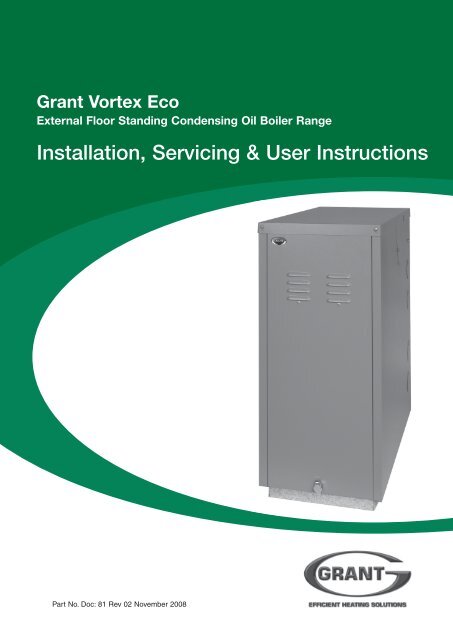
<strong>Grant</strong> <strong>Vortex</strong> <strong>Eco</strong>External Floor Standing <strong>Condensing</strong> Oil Boiler RangeInstallation, Servicing & User InstructionsPart No. Doc: 81 Rev 02 November 2008
LIST OF CONTENTSSection SubjectPage1 Introduction .............................................. 32 User instructions ...................................... 43 Boiler technical information .................... 74 General boiler information....................... 105 Condensate disposal ................................. 196 Boiler installation ..................................... 227 Commissioning......................................... 308 Information for the user ........................... 329 Boiler servicing ........................................ 3310 Wiring diagrams ....................................... 3611 Fault finding ............................................. 3812 Boiler spares ............................................ 4013 Burner spares ........................................... 4114 Health and safety information .................. 4215 EC declaration of conformity .................. 43COMMISSIONING REPORTDate: ..............................Commissioning engineer: .............................................................................. Tel. No: ....................................Boiler model/output: ........................................ kW Fuel type: KeroseneNozzle size: .................................... Pump pressure: .................... Air setting: ...........................Flue gas % CO 2 : ............................. Net flue gas temp:................ Smoke No:...........................SERVICE LOGIt is recommended that the boiler should be regularly serviced, at least once a year, and the details entered in the BoilerHandbook by the service engineer.2 <strong>Grant</strong> <strong>Vortex</strong> <strong>Eco</strong> External Module
1 - INTRODUCTION1.1 How a condensing boiler works1.2 Heating system design considerationsDuring the combustion process, hydrogen and oxygencombine to produce heat and water vapour. The watervapour produced is in the form of superheated steam inthe heat exchanger. This superheated steam containssensible heat (available heat) and latent heat (heatlocked up in the flue gas). A conventional boilercannot recover any of the latent heat and this energy islost to the atmosphere through the flue.The <strong>Grant</strong> <strong>Vortex</strong> condensing boiler contains an extraheat exchanger which is designed to recover the latentheat normally lost by a conventional boiler. It does thisby cooling the flue gases to below 90° C, thusextracting more sensible heat and some of the latentheat. This is achieved by cooling the flue gases to theirdew point (approximately 55° C).To ensure maximum efficiency, the boiler returntemperature should be 55° C or less, this will enablethe latent heat to be condensed out of the flue gases.The boiler will achieve nett thermal efficiencies of100%.To achieve maximum performance from the <strong>Grant</strong><strong>Vortex</strong> boiler, it is recommended that the heatingsystem is designed so that a temperature differential of20° C between the flow and return is maintained. Theuse of modulating circulating pumps (now widelyavailable) and effective control systems should beconsidered.To achieve the maximum efficiencies possible fromthe <strong>Grant</strong> <strong>Vortex</strong> boiler, the heating system should bedesigned to the following parameters:Radiators:-Flow temperature 70° CReturn temperature 50° CDifferential 20° CUnderfloor:-Flow temperatureReturn temperatureDifferential50° C40° C10° C1 Size radiators with a mean water temperature of60° C.2 Design system controls with programmable roomthermostats or use weather compensating controlsto maintain return temperatures below 55° C.The boiler should not be allowed to operate withreturn temperatures of less than 40° C when thesystem is up to operating temperature.3 The use of a pipe stat is recommended to controlthe return temperature when using weathercompensating controls.The <strong>Grant</strong> <strong>Vortex</strong> boiler will however still operate atextremely high efficiencies even when it is not incondensing mode and therefore is suitable for fitting toan existing heating system without alteration to theradiator sizes. The boiler is capable of a maximumflow temperature of 75° C.<strong>Grant</strong> <strong>Vortex</strong> <strong>Eco</strong> External Module3
2 - USER INSTRUCTIONS2.1About your boiler2.3Lighting your boiler (see Fig. A)The boiler is fully automatic once switched on, providingcentral heating (and also heating your domestic hot waterif you have a hot water cylinder fitted).A 'mains on' neon, see Fig. A, lights when the boiler isswitched on, but does not necessarily indicate the burneris firing.If your system includes a remote programmer, theboiler will provide hot water and central heatingduring the periods set on the programmer.2.2Boiler controls (see Fig. A)To gain access to the controls, remove the front panelby turning the handle and withdrawing it forwards atthe bottom.1 Ensure that - There is sufficient fuel, of the correcttype, in the supply tank and all fuel supply valves areopen. The water supply is on. The electricity supplyto the boiler is off. The boiler On/Off switch is set toOFF. The Test switch is set to OFF. The roomthermostat (if fitted) is at the desired setting. Theboiler thermostat is set to the required setting (seeSection 2.7).2 Switch on the electricity supply to the boiler.3 Set the boiler On/Off switch to ON and, if fitted,the remote programmer (CH or HW) to ON.The boiler will now light automatically.4 If you have a remote programmer fitted in yoursystem, refer to the instructions supplied with theprogrammer and set the programmer. Set the HW andCH functions to TIMED. The boiler will now operateduring the 'on' periods set on the programmer.Controls for External modules - Fig. A4 <strong>Grant</strong> <strong>Vortex</strong> <strong>Eco</strong> External Module
2 - USER INSTRUCTIONS2.4Turning off your boiler (see Fig. A)2.7General notes and care of your systemFor short periods - Set the boiler On/Off switch to OFF.To restart, simply set the switch to ON.For long periods: Set the boiler On/Off switch to OFFand switch off the electricity supply to the boiler. Ifrequired, the fuel supply valve may be closed and thewater and electricity supplies turned off at the mains.Note: If the electricity, fuel and water supplies are turnedoff, the built-in frost thermostat will not operate.To restart, refer to the full lighting instructions givenin Section 2.3.2.51 Check that the boiler On/Off switch is ON.2 Check that any remote programmer (if fitted) isworking and is in an 'on' period.3 Check that all thermostats are set to the desiredsetting and are calling for heat.4 Check if the burner 'Lock-out' reset button (on theburner) is lit. If it is, press it to start the burner. Ifthe burner fails to light and goes to 'Lock-out'again, check that you have sufficient fuel in thestorage tank and that the fuel supply valve is open.Check that the fire valve in the oil supply line has nottripped5 Ensure that a fuse has not blown or that theelectricity supply has not failed.6 Check to see if the safety thermostat has operated(see Section 2.7).If the burner still fails to light after carrying out thesechecks then a fault exists. Switch off the electricitysupply to the boiler and contact your Service engineer.2.6Points to check if burner fails to lightAbout your fuel<strong>Grant</strong> <strong>Vortex</strong> External modules operate on Class C2Kerosene only. You should always quote the type of fuelyou require when ordering from your supplier.Do not wait until the fuel runs out before you ordersome more. Sludge in the bottom of the tank may bedrawn into the fuel lines. If it is possible, switch off theboiler when the new supply is delivered and leave thefuel to settle for an hour before restarting the boiler.1 Boiler thermostat - This control allows thetemperature of the water leaving the boiler to heatthe radiators and domestic hot water to be adjusted.Note: If you have a cylinder thermostat on your hotwater cylinder, this will control the temperature ofyour domestic hot water. The boiler thermostatsetting must be equal to or above the cylinderthermostat setting to enable the cylinder thermostatto control the domestic hot water system.2 Burner Lock-out reset button - If there is aburner malfunction, a built-in safety circuitswitches the burner off and the 'Lock-out' resetbutton (on the burner) will light. Usually suchmalfunctions are short lived and pressing the resetbutton will restore normal operation.If the burner continually goes to 'Lock-out' a faultexists or the fuel supply is low. If you havesufficient fuel, you will need to call your Serviceengineer.3 Safety thermostat - Your boiler is fitted with asafety overheat thermostat which will automaticallyswitch off the boiler in the case of a controlmalfunction causing overheating.If your boiler goes off and you try to light it butnothing happens and the 'Lock-out' reset button onthe burner is not lit, the overheat thermostat hasprobably operated. The boiler will not light untilthe thermostat is reset. To reset, unscrew the smallplastic cap (see Fig. A), press the button thenreplace the cap.If this condition continually repeats, contact yourService engineer.4 Ventilation - Always ensure that the boiler hasadequate ventilation. Any ventilation openingsmust not be obstructed. Periodically check thatthey are clear.Do not attempt to 'box in' the boiler or build acompartment around.Do not place any combustible material around oron the boiler or flue pipe.Do not place anything against the door of theExternal modules that might obstruct theventilation openings.<strong>Grant</strong> <strong>Vortex</strong> <strong>Eco</strong> External Module5
2 - USER INSTRUCTIONS5 Flue terminal - The flue terminal must not beobstructed or damaged.In severe conditions check that the terminal doesnot become blocked by snow.6 Frost protection - Your Installer may have fitted afrost thermostat. If not, and you are likely to beaway for a short time, leave the boiler on with theboiler thermostat set at a low setting. For longerperiods the boiler and system should be drained.Contact your Service engineer for draining andfilling the system.The control panel of the External modules includesa built-in frost thermostat factory set to 5°C.Note: For <strong>Vortex</strong> External modules we recommendthat a combined antifreeze and corrosion inhibitorbe used in the primary water system.7 Cleaning and servicing - Lightly wipe over thecase with a damp cloth and a little detergent. Donot use abrasive pads or cleaners.You must have your boiler serviced at least once ayear to ensure safe and efficient operation. Contactyour Service engineer for further details.Note: External equipment operated at 230 voltsshould not be serviced or repaired under adverseweather conditions.8 Failure of electricity supply - If the electricitysupply fails, the boiler will not operate. It shouldrelight automatically when the supply is restored.2.8The boiler requires a 230/240 V ~ 50 Hz supply. Itmust be protected by a 5 Amp fuse.Warning: This appliance must be earthed.2.9Electricity supplySealed central heating systemIf your boiler is operating on a sealed heating system,the installer will have pressurised the system andshould have told you (or set it on the pressure gauge)the system pressure when cold (this is normallybetween 0.5 and 1.0 bar, which will increase slightlywhen hot). If the pressure (when cold) is below the setpressure mentioned above, you can re-pressurise thesystem. If the system requires frequent re-pressurising,ask your Installer or Service engineer to check theheating system for leaks and to check the expansionvessel air charge.The boiler or system will be fitted with an automaticair vent to remove air from the system. Any air trappedin the radiators should be removed by venting theradiators using the vent screw at the top of eachradiator. Only vent a radiator if the top is cool and thebottom is hot. Excessive venting will reduce thesystem pressure, so only vent when necessary andcheck the system pressure as mentioned above. Repressurisethe system if necessary.The boiler or system may be fitted with a safety valveto release excess pressure from the system. If water orsteam is emitted from the end of the safety valvedischarge pipe, switch off the boiler and contact yourInstaller or Service engineer.The expansion vessel air charge must be checkedannually. Failure to maintain an adequate aircharge in the vessel may invalidate the warranty.To re-pressurise the system by adding water:1 Only add water to the system when it is cold andthe boiler is off. Do not overfill.2 Ensure the flexible filling loop (see Fig. B) isconnected and that the shut off valve connecting itto the boiler is open and the double check valve atthe front is closed.A valve is open when the operating lever is in line withthe valve, and closed when it is at right angles to it.3 Gradually open the double check valve on the frontof the filling loop until water is heard to flow.4 Vent each radiator in turn, starting with the lowestone in the system, to remove air.5 Continue to fill the system until the pressure gaugeindicates between 0.5 and 1.0 bar. Close the fillpoint valve.6 Repeat steps 4 and 5 as required.7 Close the valves either side of the filling loop anddisconnect the loop.CentralheatingsystemPressure gaugeShut off valveFlexible filling hoseDouble check valveMainswatersupplySealed system filling loop arrangement - Fig. B6 <strong>Grant</strong> <strong>Vortex</strong> <strong>Eco</strong> External Module
3 - BOILER TECHNICAL INFORMATION3.1Boiler technical dataModelWater contentlitregal15/21132.9* Weight (dry) kglb103227Max. heat output kW20.7(kerosene)Btu/h70 600Flow connectionReturn connection22 mm22 mmMin. flow rate (ΔT=10°C) l/h1 780Min. flow rate (ΔT=20°C) l/h890Condensate connectionFlue diameter (conventional)Waterside resistanceFlow/Return temp. diff. of 10°CFlow/Return temp. diff. of 20°CMaximum static headMinimum circulating headBoiler thermostat rangeLimit (safety) stat shut off tempMax. hearth temperatureElectricity supplyMotor powerWattsStarting current AmpsRunning current AmpsOil connectionConventional flueMax operating press - sealed sysMax operating press - open sys* Weight includes burner but excludes flue.<strong>Vortex</strong> <strong>Eco</strong> External module21/26132.910322725.687 35022 mm22 mm2 2001 10022 mm (only connect plastic pipe)100 mm28.5 mbar10 mbar28 m1m65 to 75° C111° C ± 3° CLess than 50° C230/240 V ~ 50 Hz Fused at 5 Amp904.20.85¼" BSP Male (on end of flexible fuel hose)Minimum flue draught - 8.7 N/m² (0.035 in wg)Maximum flue draught - 37 N/m² (0.15 in wg)2.5 bar2.5 bar26/35194.212126734.7118 40022 mm22 mm2 9801 490<strong>Grant</strong> <strong>Vortex</strong> <strong>Eco</strong> External Module7
3 - BOILER TECHNICAL INFORMATION3.2Sealed system data - <strong>Eco</strong> External modules with sealed system kitHeating system pressure (cold)Operating pressure of pressure relief valveExpansion vessel sizeMax heating system volume (including boiler)*Cold water mains connection (for filling loop)Pressure relief valve discharge connectionMaximum 1.0 bar, Minimum 0.5 bar2.5 bar12 litres (pre-charged at 1 bar)128 litres (approximately)15 mm compression (provided)15 mm compression (provided)* Based on vessel charge and system cold fill pressure of 0.5 bar3.3<strong>Grant</strong> <strong>Vortex</strong> <strong>Eco</strong> oil boilers using Class C2 keroseneNote: <strong>Grant</strong> <strong>Vortex</strong> <strong>Eco</strong> boilers are only for use with kerosene.Model andburner type15/21Riello RDB2.221/26Riello RDB2.226/35Riello RDB2.2Heat Output(kW) (Btu/h)15.1 51 500* 18.1 61 75020.7 70 60020.7 70 600* 22.7 77 50025.6 87 35025.6 87 350* 30.8 105 10034.7 118 400SEDB<strong>UK</strong>efficiency(%)93.092.492.1Nozzle0.50/80°EH0.55/80°EH0.60/80°EH0.60/80°EH0.65/80°EH0.75/80°EH0.75/80°EH0.85/80°EH1.00/80°EHOilpress.(bar)7.07.58.58.58.58.08.09.18.0SmokeNo.0 - 10 - 10 - 10 - 10 - 10 - 10 - 10 - 10 - 1BurnerheadtypeT1T1T1T1T2T2T2T3T3Burnerhead/discsettingDisc setting BDisc setting CDisc setting CFixedFixedFixedFixedFixedFixedFuel flowrate(kg/h)1.291.531.781.781.952.192.192.652.93Flue gas temp °CFlue Door70 - 75 155 - 16075 - 80 175 - 18080 - 85 185 - 19085 - 90 195 - 20085 - 90 205 - 21090 - 95 215 - 22075 - 80 190 - 19585 - 90 215 - 22090 - 95 220 - 225CO 2(%)11 - 1211 - 1211 - 1211 - 1211 - 1211 - 1211 - 1211 - 1211 - 12Notes:1 The data given above is approximate only and based on the boiler using a low level flue.2 The above settings may have to be adjusted on site for the correct operation of the burner.3 Gas Oil is not suitable for use with the <strong>Grant</strong> <strong>Vortex</strong> <strong>Eco</strong> boiler range.4 The net flue gas temperatures given above are ± 10%.5 When commissioning the air damper must be adjusted to obtain the correct CO 2level.6 * Factory settings: 15/21 - 18.1 kW, 21/26 - 22.7 kW, 26/35 - 30.8 kW.7 The combustion door test point may be used for CO 2and smoke readings only. Do not use this test point for temperature orefficiency readings.8 When setting the 15/21 to 15.1 kW output the burner air adjuster disc requires repositioning. Refer to Section 7 Commissioning.When setting the 21/26 to 20.7 kW output the combustion head must be changed. Refer to Section 9.2 Cleaning the burner.When setting the 26/35 to 25.6 kW output the combustion head must be changed. Refer to Section 9.4 Cleaning the burner.9 The installer must amend the boiler data label if the output is changed.Flue gas analysis1 Insert a combustion probe into the end of the flue terminal to measure the CO 2level. Do not use the test point in the cleaningdoor.To obtain the correct CO2 level the final flue gas reading must be taken with all the casing panels fitted.2 The boiler efficiency and temperature must be taken from the flue test point on high level and vertical flue adaptors.3 Low level flues do not contain a test point. The temperature and efficiency readings must be taken from the flue terminal.8 <strong>Grant</strong> <strong>Vortex</strong> <strong>Eco</strong> External Module
3 - BOILER TECHNICAL INFORMATION3.4Boiler dimensionsFig 1 - Dimensions for 15/21, 21/26. and 26/35 <strong>Eco</strong> External modules<strong>Grant</strong> <strong>Vortex</strong> <strong>Eco</strong> External Module9
4 - GENERAL BOILER INFORMATION4.1Boiler description4.3Regulations to comply with<strong>Grant</strong> External modules have an insulatedweatherproof enclosure made of galvanised steel witha powder coated finish, and are designed for externalinstallation, either against a wall or free standing somedistance away from the property, as required.For flue terminal clearances refer to page 15.The <strong>Vortex</strong> <strong>Eco</strong> External modules are part of the <strong>Grant</strong>range of automatic pressure jet oil boilers have beendesigned for use with a fully pumped central heatingsystem with indirect domestic hot water cylinder. Theyare not suitable for use with either a direct cylinder or a'primatic' cylinder or gravity hot water.The boilers are suitable for use on open vented orsealed central heating systems.All models are supplied with the control panel andburner factory fitted.The factory fitted low level discharge flue system canbe adjusted on site for either rear, left hand or righthand flue outlet position, as required.An external conventional flue (Green) system (Fig. 16) isalso available from <strong>Grant</strong> Engineering (<strong>UK</strong>) Limited.Refer to Section 6.4 for further details.A Hybrid flue (Green/Orange) system (Fig. 18) is alsoavailable which allows the External module to utilisean existing chimney stack. Refer to Section 6.4 forfurther details.4.2Boiler componentsAll burners are pre-set for use with kerosene and aresupplied ready to connect to a single pipe fuel supplysystem with a loose flexible fuel line and 3 / 8" to 1 / 4" BSPmale adaptor supplied with the boiler.If required, an additional flexible fuel line (600 mm) and3/ 8" to 1 / 4" BSP male adaptor are available to purchasefrom <strong>Grant</strong> Engineering (<strong>UK</strong>) Limited, for two-pipe oilsupply systems, Part No. RBS104.The temperature of the water leaving the boiler to heatthe radiators and hot water cylinder is User adjustable.The boiler is fitted with an overheat thermostat (whichallows it to be used on a sealed central heating system)which will automatically switch off the boiler if the heatexchanger exceeds a pre-set temperature of 111°C ± 3°C.The control panel is fitted with an ON/OFF switch,boiler thermostat control knob and the <strong>manual</strong> resetbutton for the overheat thermostat.Installation of a <strong>Grant</strong> <strong>Vortex</strong> boiler must be inaccordance with the following recommendations:-a Building Regulations for England and Wales,and the Building Standards for Scotland issuedby the Department of the Environment and anylocal Byelaws etc.b Model and local Water Undertaking Byelaws.c Applicable Control of Pollution Regulations.d The following OFTEC requirements:-OFS T100 Polythene oil storage tanks fordistillate fuels.OFS T200 Fuel oil storage tanks and tankbunds for use with distillate fuels,lubrication oils and waste oils.Further information may be obtained from theOFTEC Technical Information Book 3(Installation requirements for oil fired boilersand oil storage tanks).The installation should also be in accordance with thelatest edition of the following British Standard Codesof Practice:-BS 715 Metal flue pipes, fittings, terminalsand accessories.BS 799:5 Oil storage tanks.BS 1181 Clay flue linings and flue terminals.BS 4543:3 Factory made insulated chimneys foroil fired appliances.BS 4876 Performance requirements for oilburning appliances.BS 5410:1 Code of Practice for oil firing appliances.BS 5449 Forced circulation hot water systems.BS 7593 Code of Practice for treatment ofwater in heating systems.BS 7671 Requirements for electricalinstallations, IEE Wiring Regulations.Failure to install and commission appliancescorrectly may invalidate the boiler warranty.IMPORTANTBefore starting any work on the boiler, or fuel supplyplease read the health and safety information given inSection 14 on page 42.10 <strong>Grant</strong> <strong>Vortex</strong> <strong>Eco</strong> External Module
4 - GENERAL BOILER INFORMATIONRegional statutory requirements may deem this appliance to be a 'controlled service'.Where this is the case, it is a legal requirement that the appliance is installed andcommissioned either under the remit of building control or by a 'Competent person' suchas a suitably qualified Oftec registered technician.4.4Fuel supply4.4.1 Fuel storageThe tank should be positioned in accordance with therecommendations given in BS 5410:1:1997, which givesdetails of filling, maintenance and protection from fire.A steel tank may be used and must be constructed toBS 799:5:1987 and OFS T200.A galvanised tank must not be used.A plastic tank may be used and must comply withOFS T100.Note: Plastic tanks should be adequately anduniformly supported on a smooth level surface, acrosstheir entire base area.4.4.2 Fuel pipes1 Fuel supply pipes should be of copper tubing withan external diameter of at least 10 mm.Galvanised pipe must not be used.All pipe connections should preferably use flaredfittings. Soldered connections must not be used onoil pipes.2 Flexible hoses must not be used outside the boiler case.3 A remote sensing fire valve must be installed in thefuel supply line, with the sensing head located abovethe burner. Recommendations are given in BS5410:1:1997.4 A metal bowl type filter with a replaceablemicronic filter must be fitted in the fuel supply lineadjacent to the boiler. A shut-off valve should befitted before the filter, to allow the filter to beserviced.5 A flexible fuel hose, adaptor and 1 / 4" BSP isolationvalve are supplied loose with the boiler for the finalconnection to the burner. If a two pipe system or'Tiger Loop' type de-aerator is used, an additionalflexible fuel hose (600 mm) and 3 / 8" to 1 / 4" BSP maleadaptor are available to purchase from <strong>Grant</strong>Engineering (<strong>UK</strong>) Limited, Part No. RBS104.A de-aeration device should not be fitted within theboiler casing.6 Metal braided flexible hoses should be replacedannually when the boiler is serviced. Long lifeflexible hoses should be inspected annually andreplaced at least every 60 months.4.4.3 Single pipe system - (See Fig. 2)1 Where the storage tank outlet is above the burnerthe single pipe system should be used. The heightof the tank above the burner limits the length ofpipe run from the tank to the burner.2 As supplied the burner is suitable for a single pipesystem.HeadA(m)0.51.01.52.0FirevalvesensorPumpMaximum pipe run (m)10 mm OD pipe1020406012 mm 0D pipe2040801001 mShut-offvalveFilterFirevalveALevelgaugeShut-offvalveVentpipeFillpipeFuelstoragetankSludgevalveFig. 2 - Single pipe system<strong>Grant</strong> <strong>Vortex</strong> <strong>Eco</strong> External Module11
4 - GENERAL BOILER INFORMATIONFirevalvesensorSeesection 4.4.61 mNonreturnvalveFilterFirevalveSupplyHeadA(m)00.51.01.52.03.03.5Maximum pipe run (m)10 mm OD pipe35302520158612 mm OD pipe10010010090703020AShut-offvalveReturnLevelgaugeVentpipeFillpipeFuelstoragetankShut-offvalveSludgevalveFig. 3 - Two pipe system4.4.4 Two pipe system - (See Fig. 3)1 When the storage tank outlet is below the burner,the two pipe system should be used. The pipe runsshould be as shown in Fig. 3. The return pipeshould be at the same level in the tank as thesupply pipe, both being 75 to 100 mm above thebase of the tank. The pipe ends should be asufficient distance apart so as to prevent anysediment disturbed by the return entering thesupply pipe.2 Avoid the bottom of the tank being more than 3 mbelow the burner.3 A non-return valve should be fitted in the supplypipe together with the filter and fire valve. A nonreturnvalve should be fitted in the return pipe ifthe top of the tank is above the burner.4 To be used with a two-pipe system, the burnermust be fitted with an additional flexible fuel hose(a flexible fuel hose (600 mm) and 3 / 8" to 1 / 4" BSPmale adaptor are available to purchase from <strong>Grant</strong>Engineering (<strong>UK</strong>) Limited), Part No. RBS104. SeeSection 4.4.6.5 The pump vacuum should not exceed 0.4 bar.Beyond this limit gas is released from the oil.4.4.5 Tiger Loop system - (See Figs. 4 and 5)1 When the storage tank is below the burner, analternative to a two pipe system can be achievedusing the 'Tiger Loop' type oil deaerator. Thiseffectively removes the air from the oil supply on asingle pipe lift.2 The de-aerator is connected close to the boiler as atwo pipe system (omitting the non-return valve) asshown in Fig. 4. Refer to the manufacturersinstructions supplied with the de-aerator.The de-aerator must be mounted vertically.3 To be used with a de-aerator, the burner must befitted with an additional flexible fuel hose (aflexible fuel hose (600 mm) and 3 / 8" to 1 / 4" BSPmale adaptor are available to purchase from <strong>Grant</strong>Engineering (<strong>UK</strong>) Limited), Part No. RBS104. SeeSection 4.4.6.For guidance on installation of top outlet fuel tanks andsuction oil supply sizing, see OFTEC Technical Book 3.Available at www.oftec.org.uk12 <strong>Grant</strong> <strong>Vortex</strong> <strong>Eco</strong> External Module
4 - GENERAL BOILER INFORMATIONFirevalvesensorSeesection 4.4.6De-aeration devicee.g. Tiger LoopSee Fig. 5Supply1 mReturnVentpipeFillpipeFuelstoragetankFire valveTankmasterSludgevalveFig. 4 - De-aeration device systemRETURNFROM PUMPTiger LoopSUPPLYTO PUMP1/4" BSP femaleconnectionsSUPPLYFROM TANKFig. 5 - Tiger loop 'de-aeration' device4.4.6 Two pipe oil suppliesRiello RDB burner - See Fig. 61 The fuel pump is supplied for use with a singlepipe fuel supply system. For use on a two pipesystem, it is necessary to fit the By-pass screw (seeFig. 6) into the tapping in the return port.2 The By-pass screw is supplied in the boileraccessory pack.3 Remove the plastic burner cover (two screws).4 Remove and discard the blanking plug from thereturn connection of the pump and fit the By-passscrew using an hexagonal key.5 Connect the return oil flexible fuel hose to the pump.6 Connect the 3 / 8" to 1 / 4" BSP adaptor to the flexiblefuel hose.7 Flexible fuel hoses and adaptors are available from<strong>Grant</strong> Engineering (<strong>UK</strong>) Ltd.81 2Fig. 6 - Riello RDB pump1 Oil inlet connection2 Return connection3 By-pass screw4 Pressure gauge connection5 Pressure adjuster6 Vacuum gauge connection7 Solenoid8 Supply to nozzle76354<strong>Grant</strong> <strong>Vortex</strong> <strong>Eco</strong> External Module13
4 - GENERAL BOILER INFORMATION4.5Electricity supply4.7Boiler location1 A 230/240 V ~ 50 Hz mains supply is required.The boiler must be earthed.2 The supply must be fused at 5 Amp and there mustonly be one common isolator for the boiler andcontrol system, providing complete electricalisolation.3 A fused double pole switch or a fused three pinplug and shuttered outlet socket should be used forthe connection.4 The power supply cable should be at least 0.75 mm²PVC as specified in BS 6500, Table 16.5 All the wiring and supplementary earth bondingexternal to the boiler must be in accordance withthe current I.E.E. Wiring Regulations.6 Any room thermostat or frost thermostat used mustbe suitable for use on mains voltage.7 The boiler requires a permanent mains supply, donot interrupt it with any external time control.8 In the event of an electrical fault after installationof the boiler, the following electrical system checksmust be carried out:- Short circuit, Polarity, Earthcontinuity and Resistance to earth.1 The External Module must stand on a solid, levelsurface capable of supporting the weight of the boilerwhen full of water, e.g. a prepared concrete standing,paving slabs bedded down on sand/cement, or similar.2 The Module can be installed either against the buildingor 'free standing' some distance away from the building.3 The Module must be positioned such that therequired clearances from the low level flue outlet,as shown in Fig. 7, are achieved.4 Adequate clearance must be left around the Modulefor servicing. In particular, a minimum clearance of600 mm above the Module for removal of the toppanel and 600 mm at the opposite end to the flue outletfor access to the burner.Sufficient clearance is required at the rear of theboiler to allow the rear panel to be removed foraccess to the condensate trap.5 The flue terminal must be a minimum distance of1.8 m from an oil storage tank.The flue terminal should be positioned so as toavoid products of combustion accumulating instagnant pockets around the building or enteringinto buildings.4.6Frost protection1 External Modules are supplied with a factory fittedfrost protection thermostat, located inside theboiler control panel. This is pre-wired to the boilerelectrical system and factory set to 5°C.2 For total system protection against freezing,particularly during extended periods withoutelectrical power, <strong>Grant</strong> recommend the use of acombined heating system antifreeze and corrosioninhibitor, used in accordance with themanufacturer's instructions.14 <strong>Grant</strong> <strong>Vortex</strong> <strong>Eco</strong> External Module
4 - GENERAL BOILER INFORMATIONFig. 7 - Clearances for flue terminalsABCDEFGHIJKLTerminal positionBelow gutters, eaves or balconies (with protection)Horizontally from a door, window or air ventAbove ground, flat roof or balcony levelBelow gutters, eaves or balconies (without protection)From an external cornerFrom a terminal facing the terminalFrom a surface facing the terminalVertically from a terminal on the same wallHorizontally from a terminal on the same wallDirectly below an opening, air brick, window, etc.From a vertical drain pipe or soil pipeFrom an internal cornerMin. distance*600600300*60030012006001500**750600300300Notes: * 75 mm with protection.** Only applies if one or both terminals are balanced flues.Distances measured to rim of terminal.Clearances recommended by <strong>Grant</strong>Engineering (<strong>UK</strong>) Limited in accordance withBritish Standards and Building Regulations.Notes:1 An opening means an openableelement, such as an openablewindow, or a permanent openingsuch as a permanently open air vent.2 Notwithstanding the dimensionsgiven, a terminal should be at least300 mm from combustible material,e.g. a window frame.3 A way of providing protection ofcombustible material would be to fita heat shield at least 750 mm wide.The terminal should be positioned so as to avoid products of combustion accumulating in stagnant pocketsaround the building or entering into buildings. Care should also be taken that the plume from the condensedflue gases does not cause a nuisance.<strong>Grant</strong> <strong>Vortex</strong> <strong>Eco</strong> External Module15
4 - GENERAL BOILER INFORMATION4.8Water connectionsSee Figs. 8, 9 and 10Boiler model Flow connection Return connectionSizeFitting Supplied Size Fitting Supplied15/21, 21/26, 26/35 External 22 mm pipe Tectite elbow in fittings kit 22 mm pipe Compression fittedThe flow and return pipework can exit the boilerenclosure either through the openings provided in bothsides (under the movable cover plates) and through thewall when installed against the building, or down andthrough the openings provided in the base of theenclosure for 'free standing' installations.IMPORTANT: All pipes to be fitted into the push-fitconnectors provided should be cut using a pipe sliceror pipe cutter - to leave the pipe ends with a slightradius and free from any burrs or sharp edges. Pipes tobe used with these fittings should not be cut squareusing a hacksaw.Fit drain cocks in the central heating and domestic hotwater systems to allow the complete system to be fullydrained.To avoid the danger of dirt and foreign matter enteringthe boiler the complete heating system should bethoroughly flushed out - before the boiler is connectedand then again after the system has been heated and isstill hot. This is especially important where the boileris used on an old system.For optimum performance after installation, this boiler and itsassociated central heating system must be flushed in accordancewith the guidelines given in BS 7593:1992 'Treatment of waterin domestic hot water central heating systems'.This must involve the use of a proprietary cleaner,such as BetzDearborn's Sentinel X300 or X400, orFernox Restorer. Full instructions are supplied withthe products, but for immediate information, pleasecontact BetzDearborn on 0151 4209563 or Fernox on0179 9550811.For Long term protection against corrosion and scale,after flushing, it is recommended that an inhibitor such asBetzdearborn's Sentinel X100 or Fernox MB-1 is dosedin accordance with the guidelines given in BS 7593:1992.Failure to implement the guidelines will invalidate thewarranty.Fig. 8 - Top view16 <strong>Grant</strong> <strong>Vortex</strong> <strong>Eco</strong> External Module
4 - GENERAL BOILER INFORMATIONSealing cap must be fittedFlexible hose from outlet ofcondensing heat exchangerCondensate trapCondensate outlet to drainFig. 9 - Rear view (panel removed)4.9Sealed system kitSee Fig. 10<strong>Grant</strong> sealed system kits, incorporating circulatingpumps are available. See Section 6.5 and 6.6.1 The boiler is only suitable for use with a sealedsystem complying with the requirements of BS 5449.The maximum temperature of the central heatingwater is 75°C.2 The system must be provided with the followingitems:-a Diaphragm expansion vessel complying withBS 4814.b Pressure gauge.c Safety valve.d Approved method for filling the system.Refer to BS 7074:1 for further guidance.3 The expansion vessel can be fitted in either thereturn or flow pipework in any of therecommended positions as shown in Fig. 10. Toreduce the operating temperature of the expansionvessel diaphragm, position it below the pipe towhich it is connected. The expansion vessel may bepositioned away from the system, providing theconnecting pipe is not less than 13 mm diameter.4 The pressure gauge should have an operating rangeof 0 to 4 bar.5 The safety valve, set to operate at 2.5 bar, shouldbe fitted in the flow pipework near to the boiler.The pipework between the safety valve and boilermust be unrestricted, i.e. no valves. The safetyvalve should be connected to a discharge pipewhich will allow the discharge to be seen, butcannot cause injury to persons or property.Fig. 10 Sealed system<strong>Grant</strong> <strong>Vortex</strong> <strong>Eco</strong> External Module17
4 - GENERAL BOILER INFORMATION6 Provision should be made to replace water lostfrom the system. This can be done <strong>manual</strong>ly (whereallowed by the local water undertaking) using anapproved filling loop arrangement incorporating adouble check valve assembly.7 An automatic air vent should be fitted to thehighest point of the system, as the air vent fitted tothe boiler is for venting the boiler only.8 The system design pressure (cold) should be between0.5 and 1.0 bar. This pressure is equivalent to themaximum static head in bar + 0.3 (1 bar = 10.2 metresof water).9 All fittings used in the system must be able towithstand pressures up to 3 bar.10 Radiator valves must comply with the requirementsof BS 2767(10):1972.11 One or more drain taps (to BS 2879) must be usedto allow the system to be completely drained.12 For proprietary expansion vessel/valve/gaugepacks, refer to the manufacturers instructions forthe correct location on the heating system.4.10Water connections - Sealed system kitAlso refer to Sections 6.5 and 6.6.1 A 15 mm discharge pipe must be connected to thesafety valve outlet connection. The pipework betweenthe safety valve and the boiler must be unrestricted,i.e. no valves. The discharge pipe should terminate sothat it cannot cause injury to persons or property.2 A 15 mm double check valve ballofix type valve isprovided on the flexible filling loop hose forconnection of the cold mains supply to the heatingsystem. The cold mains supply should terminateinside the boiler casing.3 A drain cock is fitted at the bottom on the front ofthe boiler to allow the heating system to be drained4 The expansion vessel is connected via a flexiblehose to allow it to be moved to gain access to thebaffle cleaning cover. When replacing the vessel,care should be taken to ensure that the flexibleconnecting hose is not twisted.4.11On underfloor systems it is essential that the returntemperature must be maintained above 40° C toprevent internal corrosion of the boiler water jacket.4.12Underfloor heating systemsPipework materialsGeneral - <strong>Grant</strong> boilers are compatible with bothcopper and plastic pipe. Where plastic pipe is used itmust be of the oxygen barrier type and be of thecorrect class (to BS 7291:Part 1:1990) for theapplication concerned.IMPORTANT: The first metre of pipeworkconnected to both the heating flow and returnconnections of the boiler must be made in copper onall types of system - sealed or open-vented.Sealed systems - If plastic pipe is to be used, theinstaller must check with the plastic pipe manufacturerthat the pipe to be used is suitable for the temperatureand pressures concerned. Pipe must be Class S to BS7291: Part 1:1990.The system should incorporate a low-pressure switchto shut off power to the boiler if the system pressuredrops below 0.2 bar. A suitable low pressure switch kitis available to purchase from <strong>Grant</strong> Engineering (<strong>UK</strong>)Limited, Part No. MPCBS 63.Underfloor systems - Plastic pipe may be used onUnderfloor systems where the plastic pipe is fittedafter the thermostatic mixing valve. Copper tube mustbe used for at least the first metre of flow and returnprimary pipework between the boiler and theunderfloor mixing/blending valves.18 <strong>Grant</strong> <strong>Vortex</strong> <strong>Eco</strong> External Module
5 - CONDENSATE DISPOSAL5.1General requirements5.3PipeworkWhen in condensing mode the <strong>Grant</strong> <strong>Vortex</strong> <strong>Eco</strong>boilers produce condensate from the water vapour inthe flue gases. This condensate is slightly acidic with aph value of around 3 (similar to vinegar). Provisionmust be made for the safe and effective disposal of thiscondensate.Condensate can be disposed of using one of thefollowing methods of connection:Internal connection (preferred option)• into an internal domestic waste system (fromkitchen sink, washing machine, etc.)• directly into the soil stackExternal connection• into an external soil stack• into an external drain or gulley• into a rainwater hopper (that is part of a combinedsystem where sewer carries both rainwater and foulwater)• purpose made soakawayAll condensate disposal pipes MUST be fitted with atrap - whether they are connected internally orexternally to a domestic waste system/soil stack or runexternally to a gully, hopper or soakaway.5.2ConnectionsConnections into a rainwater hopper, external drain orgulley should be terminated inside the hopper/drain/gulley below the grid level but above the water level.Condensate disposal pipes should not be connecteddirectly into rainwater downpipes or to waste/soilsystems connected to septic tanks.Condensate should not be discharged into 'grey water'systems that re-use water used in the home (notincluding water from toilets).It should be noted that connection of a condensate pipeto the drain may be subject to local Building Controlrequirements.Condensate disposal pipework must be plastic (plasticwaste or overflow pipe is suitable).IMPORTANT: Copper or steel pipe is NOT suitableand MUST NOT be used.Condensate disposal pipes should have a minimum'nominal' diameter of 22 mm (¾") - e.g. use 21.5 mmOD polypropylene overflow pipe.Condensate disposal pipes must be fitted with a fall(away from the boiler) of at least 2.5° (~45 mm fallper metre run).Note: Where it is not possible for the pipe to falltowards the point of discharge - either internally into awaste system or externally to a gulley (e.g. for boilersinstalled in a basement), it will be necessary to use acondensate pump.Condensate disposal pipes should be kept as short aspossible and the number of bends kept to a minimum.Pipes should be adequately fixed to prevent sagging,i.e. at no more than 0.5 metre intervals.External pipeworkIdeally, external pipework, or pipework in unheatedareas, should be avoided. If unavoidable, externalpipework should be kept as short as possible (less than3 metres) and 32 mm waste pipe used to minimise therisk of ice blocking the pipe in freezing conditions.The number of bends, fittings and joints on externalpipes should be kept to a minimum to reduce the riskof trapping condensate.Note: For boiler installed in an unheated area such asan outhouse or garage, all condensate pipework shouldbe considered as an ‘external’.5.4Condensate soakawayTo keep external pipework to a minimum, locate thesoakaway as close as possible to the boiler but ensureit is at least 1 metre from building foundations andaway from other services, e.g. gas, electricity, etc.The condensate pipe may be run above or belowground level and can enter either the top or side of thesoakaway tube. Refer to Fig.11.Ensure that the drainage holes in the soakaway tubeface away from the building.Backfill both the soakaway tube, and the hole aroundit, with 10 mm limestone chippings.<strong>Grant</strong> <strong>Vortex</strong> <strong>Eco</strong> External Module19
5 - CONDENSATE DISPOSALOnly use a soakaway where the soil is porous anddrains easily. Do not use in clay soils or where thesoil is poorly drained.WARNING: Any damage due to condensate backingup into the boiler due to a high water table, in the caseof a soakaway, or flooded drains when the condensatedisposal is via a gulley or soil stack, is not covered bythe <strong>Grant</strong> product warranty.32 mm waste pipe external to the buildingCement sealO2.5 fallGround level25 mm300 mm400 mmmin.100 mmplastictubeSealedendBackfill with 10 mmlimestone chippingsTwo rows of 3 x 12 mmholes at 25 mm centresand 50mm from the bottomof the tube. Holes facingaway from the property.Fig. 11 - Purpose made condensate soakaway5.5Condensate trap<strong>Grant</strong> <strong>Vortex</strong> <strong>Eco</strong> External modules are supplied with afactory-fitted condensate trap to provide the required 75 mmwater seal in the condensate discharge pipe from the boiler.This trap incorporates a float (which will create a sealwhen the trap is empty) and an overflow warningoutlet (fitted with a plastic sealing cap), See Fig. 12.Overflow warningoutlet(with cap)Condensateoutlet to drainCondensate drain pipefrom boilerCondensate trapThe trap is factory-fitted inside the boiler casing,mounted in the rear of the boiler (opposite end to theburner) on the inside of the right hand side panel - inan accessible position to allow for routinemaintenance. See Fig. 9.A flexible hose connects the outlet of the condensingheat exchanger to the trap inlet. Ensure the straightconnector on the hose is fully pushed onto the 'top hat'inlet connector of the trap.With the trap fitted inside the boiler casing, the sealingcap MUST be fitted.If connecting the condensate discharge (either internallyor externally) into a waste system or soil stack - thesealing cap MUST be fitted in the trap outlet.Fig. 12 - Condensate trap20 <strong>Grant</strong> <strong>Vortex</strong> <strong>Eco</strong> External Module
5 - CONDENSATE DISPOSAL5.6 Condensate disposal pipework5.7 Inspection and cleaning of trapThe condensate trap outlet is at an angle of 48° belowthe horizontal. This is to automatically give a 3° fall onany 'horizontal' runs of condensate disposal pipe. Referto Fig.11.The outlet of the trap will accept 21.5 mm to 23 mmOD Polypropylene overflow pipe for the condensatedischarge pipe.Possible routes for disposal pipeworkThe casing of the <strong>Vortex</strong> <strong>Eco</strong> External module hasseveral 50 mm diameter openings in both the sides andbase of the casing. These are designed to allowpipework to pass through the casing, as required, tosuit the installation. These openings can be used toallow the condensate disposal pipe to exit the casing inone of the following ways:Side outlet – The lower opening on either side of theboiler casing can allow the condensate disposal pipe tobe installed as follows:• Connection to an internal stack – passing backthrough the wall of the house• Connection to an external soil stack adjacent to theboiler• Discharge into an adjacent (external) drain orgulley• Discharge into a soakaway – with pipe either aboveor below ground levelThe trap MUST be checked at regular intervals (e.g.on every annual service) and cleaned as necessary toensure that it is clear and able to operate.Note: The bottom bowl is sealed to the trap body andcannot be removed.To inspect and clean the trap:1 Disconnect flexible condensate hose from inletconnector.2 Unscrew the inlet connection nut.3 Remove the inlet connector and nut from trap.4 Disconnect condensate outlet pipe from trap.5 Remove trap from bracket.6 Remove float from trap – clean if necessary.7 Inspect inside of trap and clean as necessary.8 Re-assemble trap, re-fit to boiler and re-connectflexible hose. Ensure that hose is fully pushed ontothe trap inlet connector.IMPORTANT: Failure to regularly check and cleanthe condensate trap may result in damage to the boilerand will not be covered by the Product Warranty.Bottom outlet – There are three openings in the baseof the boiler casing that can allow the condensatedisposal pipe to be installed as follows:• Discharge into a drain or gulley beneath the boiler(e.g. drain built in to the concrete base for theboiler)• Discharge into a soakaway – with pipe belowground level<strong>Grant</strong> <strong>Vortex</strong> <strong>Eco</strong> External Module21
6 - BOILER INSTALLATION6.1Unpack the boiler1 Carefully remove the packaging from the boilerand lift it off the pallet.2 The flue terminal guard is supplied loose inside theboiler.3 Remove the case top panel (four screws).4 The flue may exit the casing from the left, right or rearof the casing. The casing has two removable blankingpanels and a flue exit panel. Fit the panel with the flueexit hole and seal in the required position.5 Slacken the wing nuts holding the flue elbow androtate the elbow to the required direction for theflue to exit the casing.6 Push the end of the flue terminal section with thered seal through the seal in the casing. The terminalhas been factory lubricated. Take care not todislodge or damage the red seals.7 Carefully insert the terminal into the flue elbow untilthe bend of the terminal contacts the outer casing,then, pull the terminal forward approximately 25 mmand rotate the bend so that the outlet is horizontal.Rear Exit - The flue must discharge away from thebuilding.Side Exit - The flue should discharge towards therear of the casing to prevent flue gases re-enteringthe boiler casing through the air inlet vents on thecasing front door.The flue terminal must be fitted horizontally toprevent dripping from the end of the terminal.8 Tighten the wing nuts holding the flue elbow and fit thestainless steel flue guard using the two screws provided.9 The top panel of the casing has been designed so thatit may be fitted to create a slight slope away from theside positioned against the wall. To tilt the top panel,loosen the four top panel casing screws, one at eachcorner and push down on the side furthest from thewall. Tighten the screws. See Fig. 13.6.2Preparations for installation1 If the boiler is to be fitted against the wall, prepare thewall to accept the heating system pipework. To markthe wall for drilling, refer to Fig. 1 for the positions ofthe pipework openings in the enclosure sides.Note: Pipework should be insulated where itpasses through the wall into the boiler enclosure.If the boiler is to be installed 'free standing' (i.e.away from a wall) and the pipework rununderground, slide away the covers to open the twopipe openings in the base of the boiler enclosure.Using a sharp knife, cut through the polystyrene inthe base, around the edge of the holes, to allow theflow and return pipes to enter the enclosure.2 The electrical supply to the boiler should be routedthrough the wall in a suitable conduit, such that itenters the boiler enclosure via one of the unusedpipework openings. The cable can be routed to thefront of the boiler, for connection to the boilercontrol panel, either over the top or beneath theboiler heat exchanger. Heat resistant PVC cable, ofat least 1.0 mm² cross section should be usedwithin the boiler enclosure.Fig. 1322 <strong>Grant</strong> <strong>Vortex</strong> <strong>Eco</strong> External Module
6 - BOILER INSTALLATION3 The oil supply line should be installed up to theposition of the boiler. Refer to Section 4.4.2 fordetails. The final connection into the boiler enclosurecan be made with 10 mm soft copper, routed along thebase of the enclosure (either between the enclosureand wall or in front of the enclosure) to enter throughone of the holes located in the bottom edge side panel,at the front (burner) end.6.3Make the water connectionsRefer to Section 4.8 and 4.10 and Figs. 8, 9, or 10. forthe size, type and position of the connections.The Flow and Return pipework can be routed to eitherside of the boiler as required.For condensate disposal pipework refer to Section 5.IMPORTANT: All pipes to be fitted into the push-fitconnectors provided should be cut using a pipe sliceror pipe cutter - to leave the pipe ends with a slightradius and free from any burrs or sharp edges. Pipes tobe used with these fittings should not be cut squareusing a hacksaw.1 To gain access to the water connections, removethe two screws securing the bottom of the backpanel and remove it by withdrawing it forwards atthe bottom. Remove the top casing panel.2 To gain access to the burner, remove the frontpanel by turning the handle and withdrawing itforwards at the bottom..3 If required, fit the <strong>Grant</strong> sealed system kit, seeSection 6.5.4 Carefully manoeuvre the boiler in position to lineup with pipework through the wall. Complete thewater connections.Note: Check that the baffles are in position andthat the cleaning cover is correctly fitted and agood seal made.5 If the boiler is installed against a wall, fit the wallflashing strip. Position the strip with the bottomedge of the wider flange 20 mm above theenclosure top panel, with the narrow flange (withthe three fixing holes) flat against the wall. Thestrip should overhang the top panel by an equalamount at each end.Mark the position of the three fixing holes onto thewall, drill and plug the wall and secure the stripwith suitable screws (not supplied).If the <strong>Grant</strong> sealed system kit is fitted, refer to Section6.6 for details on filling and venting the sealed heatingsystem.6.4Flue systemsSee Figs. 14, 15 and 16Where it is not practical to use the factory suppliedlow level flue, the <strong>Vortex</strong> External Module may befitted with alternative flue systems available from<strong>Grant</strong> Engineering (<strong>UK</strong>) Limited.<strong>Grant</strong> Green system - This vertical twin wall stainlesssteel insulated flue system connects to an insulated boilerconnector elbow (complete with test point) to replace thelow level terminal and flue guard supplied with the boilerand may terminate at high level or vertically as required.See Fig. 14.<strong>Grant</strong> Hybrid system - This vertical option allows theuse of an existing chimney using part of the 'Green'system and the flexible liner and terminal of the <strong>Grant</strong>'Orange' system. See Fig. 16.Horizontal system - This option uses a straight boilerconnector, elbows and extensions as shown in Fig. 15.A complete list of flue components are given on page 25.All flue components are stainless steel and fully insulatedwith 'O' ring seals and locking bands.1 The flue must terminate in a down draught free area,i.e. at least 600 mm above the point of exit through theroof or preferably above the ridge level.2 The condensate may be allowed to run back intothe boiler. A condensate drain at the base of theflue system is not required.3 The flue terminal must be at least 600 mm fromany opening into the building, and 600 mm aboveany vertical structure or wall less than a horizontaldistance of 750 mm from the terminal.It is important to ensure that the flue system is sealedand that condensate cannot escape. Up to 1.5 l/h ofcondensate can be produced in a conventional fluesystem.6 Fill and vent the water system and check for leaks,rectifying where necessary.<strong>Grant</strong> <strong>Vortex</strong> <strong>Eco</strong> External Module23
6 - BOILER INSTALLATIONVerticalterminalVertical terminalO45 elbowHigh level 90° terminalMaximum verticallength 19 metres45° elbowsHigh level90° terminalExtensionsExtended wall bracketWall bracketLocking band950 mmExtensions450 mm195 to 270 mm250 mm150 mm45° elbowStarter elbowStarter elbowStarter - straightOutdoormodulevertical/highlevel flueoptionsStraight terminalTwin wall to singlewall adaptorFig. 14 - Vertical external conventional flue (Green system)Components for Outdoor flue systemGarden wallExtensionsMaximum horizontallength 3 metresStraightstarterOutdoormodule45° elbowsStraightterminalsGarden wallFig. 15 - Horizontal external flue24 <strong>Grant</strong> <strong>Vortex</strong> <strong>Eco</strong> External Module
6 - BOILER INSTALLATIONFlaunchingBrick chimneyTerminalClampTop plateStainless steel flex liner(see Orange system flue kit)Rigid to flexi flue connector(supplied in Orange system kit)O45 Elbow(Green system)Twin-wall to single-wall adaptorFlue extension (Green system)Adjustable extension (Green system)O45 Elbow (Green system)Flue extension (Green system)Outdoor module Starter elbowOutdoor moduleFig. 16 - Vertical Hybrid flue (Green to Orange system)The following flue components are available from <strong>Grant</strong> Engineering (<strong>UK</strong>) Limited15/21, 21/26 and 26/35 modulesItemExternal starter elbowExternal starter - straight150 mm extension250 mm extension450 mm extension950 mm extension195-270 mm adjustable extension45° elbowHigh level terminalVertical terminalWall bracket - standardWall bracket - extendedTwin wall to single wall adaptorStraight terminal - Horizontal fluePart No.GKM90GKM90CGX150/90GX250/90GX450/90GX950/90GXA250/90GE45/90GTH90GTV90GWB90GEB90GFCON80GTL90<strong>Grant</strong> <strong>Vortex</strong> <strong>Eco</strong> External Module25
6 - BOILER INSTALLATION6.5Sealed system kit1 The kit includes the following items:Pressure relief valveAutomatic air ventManifold pipe12 litre expansion vesselFlexible expansion vessel hose and sealing washerFilling loop kit - including pressure gauge mountedon shut-off valve6 m head circulating pump with 22 mm gate typevalves15 mm copper pressure relief valve discharge pipe(in two pieces)½" BSP black iron Tee - NOT REQUIRED forexternal boilersPump support bracket (with fixing screws)2 Unscrew the burner securing nut and remove theburner from the boiler.3 Remove the ½" BSP black iron plug from the frontof the boiler waterway, using a 3 / 8" drive socketwrench.4 Fit the ½" BSP straight connector end of theflexible expansion vessel hose into the tapping onthe front of the waterway using a suitable threadsealant (not supplied).5 Position the 12 litre expansion vessel on the frontof the boiler combustion door, locating the vesselbracket into the cut-out in the front of thecombustion door.Note: On 15/21 and 21/26 models, press on thepre-cut section in the centre of the door to form thecut-out for the bracket.6 Fit the ¾" BSP connection of the flexibleexpansion vessel hose to the vessel using the blackrubber washer supplied and tighten the nut.7 Fit the pump support bracket to the vertical plateon the top of the boiler shell. Secure in place usingthe screw, nut and washer provided.8 Push the 22 mm push-fit elbow (supplied with theboiler) onto the boiler flow connection.9 Fit both pressure relief valve and automatic air ventonto the manifold pipe.10 Push the end of the manifold pipe into the push-fitelbow on the boiler flow connection, so that theautomatic air vent is to the front of the boiler.11 Fit both 22 mm pump valves to the circulatingpump using the sealing washers supplied.12 Fit the pump assembly to the open end of themanifold pipe, ensuring that the pump shaft ishorizontal and the pump motor is facing towardsthe front of the boiler with the body resting on thepump support bracket. The flow arrow on the bodyof the pump must face in the direction of flow awayfrom the boiler connection.13 Assemble the pressure relief valve discharge pipefrom the two sections of pipe provided in the kit.Connect it to the pressure relief valve outlet usingthe nut and olive supplied. Route the other end ofthe discharge pipe through the slot in the base ofthe right hand side panel. Push the panel insulationback to expose the slot.14 Re-fit the burner and tighten the fixing nut to secure.15 The filling loop should be connected, via the doublecheck valve to a 15 mm cold water mains supply pipein a convenient position inside the building.26 <strong>Grant</strong> <strong>Vortex</strong> <strong>Eco</strong> External Module
6 - BOILER INSTALLATION6.6Sealed system expansion vessel pressureThe expansion vessel fitted is supplied with a chargepressure of 1.0 bar (equivalent to a max. static head of10.2 metres). The charge pressure must not be lessthan the actual static head at the point of connection.Do not pressurise the vessel above 1.5 bar.The air pressure in the vessel must be checked annually.The central heating system volume, using the expansionvessel as supplied, must not exceed the recommendedvolumes. If the system volume is greater, an extraexpansion vessel (complying with BS 4841) must befitted as close as possible to the central heating returnconnection on the boiler. The charge pressure of the extravessel must be the same as the vessel fitted in the boiler.Refer to BS 7074:1 for further guidance.The air charge pressure may be checked using a tyrepressure gauge on the expansion vessel Schraedervalve. The vessel may be re-pressurised using asuitable pump. When checking the air pressure thewater in the heating system must be cold and thesystem pressure reduced to zero.6.7Connect the power supplySee wiring diagrams in Section 10Note: A test switch is fitted to the control panel toallow the boiler to be test-fired. When On, theswitch by-passes the external control system.1 Undo the three screws and remove the lefthandcover from the control panel to gain access to theboiler terminal block.2 Pass the mains power supply cable through thecable grommet in the control panel, through thecable clamp and connect to the terminal block asfollows:-Live (brown) to terminal 2 - marked permanentliveNeutral (blue) to terminal 3 - marked mainsneutralEarth (green/yellow) to terminal 4 - markedmains earth3 Refer to Section 10.3 for a typical control systemwiring diagram.4 If the circulating pump is to be fitted within theboiler enclosure, the pump live must be connectedto terminal 7 of the boiler terminal block.Pass the pump power supply cable through thecable grommet in the control panel, through thecable clamp and connect to the terminal block asfollows:-Earth (green/yellow) to terminal 10 - marked ENeutral (blue) to terminal 9 - marked NLive (brown) to terminal 7Connecting the pump in this way allows it to beisolated using the isolating switch fitted in the boilercontrol panel, for servicing or maintenance work.5 Ensure that the cable clamp is tightened and that allcables are secure.6 Replace the cover on the control panel, with theyellow warning label facing outwards and secure withthe three screws.Do not switch on the electrical power to theExternal Module at this stage.6.8Connect the fuel supplySee Fig. 6If a two pipe system is to be used refer to Section 4.4.6.1 Remove the oil inlet plug from the fuel pump andconnect the elbow of the flexible fuel hose suppliedwith the boiler.2 Connect the flexible fuel hose to the rigid supplyusing the adaptor supplied. The supply enters theenclosure through one of the holes in the bottom ofthe side panels.<strong>Grant</strong> <strong>Vortex</strong> <strong>Eco</strong> External Module27
6 - BOILER INSTALLATION6.9Fill the sealed system1 Automatic air vent(s) are fitted to the top of theboiler (see Fig. 8). Check that the small cap on thetop of each air vent is screwed on fully, thenunscrew it one complete turn - the cap remains inthis position from now on.2 If the flexible filling loop is used to fill the system, ensureit is connected and that the valve connecting it to thesystem is open and the valve at the front is closed.A valve is open when the operating lever is in line withthe valve, and closed when it is at right angles to it.3 Ensure that the mains cold water supply valve is open(operating lever in line with the valve), then turn on themains cold water supply and gradually open the frontvalve on the filling loop until water is heard to flow.4 Vent each radiator in turn, starting with the lowestone in the system, to remove air.5 It is important that the pump is properly vented toavoid it running dry and damaging its bearings. Togain access to the pump for venting it is necessaryto remove the top panel.Remove the cap, then unscrew and remove the plugfrom the centre of the pump. Using a suitablescrewdriver rotate the exposed spindle about oneturn. Replace the plug and cap.6 Check the operation of the safety valve by turningthe head anticlockwise until it clicks. The click isthe safety valve head lifting off its seat allowingwater to escape from the system.Check that this is actually happening.7 Continue to fill the system until the pressure gaugeindicates between 0.5 and 1.0 bar. Close the fill pointvalve and check the system for water soundness,rectifying where necessary. Water may be releasedfrom the system by <strong>manual</strong>ly operating the safetyvalve until the system design pressure is obtained.8 The system design pressure (cold) should bebetween 0.5 bar and 1.0 bar. The pressure isequivalent to the maximum static head in bar + 0.3(1 bar = 10.2 metres of water), where the statichead is the vertical height from the centre of theexpansion vessel to the highest point of the system.9 Close the valves either side of the filling loop anddisconnect the loop.6.10CompletionPlease ensure that the OFTEC CD/10 installationcompletion report (provided with the boiler) iscompleted in full.Leave the top copy with the User. Retain the carbon copy.Ensure that the User Information pack (supplied withthe boiler) is handed over to the Householder.28 <strong>Grant</strong> <strong>Vortex</strong> <strong>Eco</strong> External Module
6 - BOILER INSTALLATION6.11Burner componentsSee Note below36278541Fig. 17 - RDB burner components1 Pump2 Control box3 Reset button with lock-out lamp4 Flange with gasket (do not remove from boiler)5 Air damper adjustment screw6 Air supply tube connection (balanced flue)7 Pump pressure adjustment screw8 Pressure gauge connectionNote:Remove the factory fitted air inlet spigot adaptor (item 6, above) from the air intake onthe top right hand side of the burner and fit the grey plastic air inlet grille in its place.<strong>Grant</strong> <strong>Vortex</strong> <strong>Eco</strong> External Module29
7 - COMMISSIONINGRefer to Fig. 18 for boiler controlsFig. 18Note: Check that the baffles are in position andthat the cleaning cover is correctly fitted and agood seal made.IMPORTANT:Check that the turbulators are in position and thatthe ends are vertical (see Fig. 21).Note: If the 21/26 model is down-rated to 20.7 kW, orthe 26/35 to 25.6 kW, the burner head must bechanged. See Section 3.3 and Sections 9.2 and 9.4.The Riello RDB 2.2 burner fitted to 15/21 boilerincorporates a secondary air adjustment shutter locatedwithin the air inlet housing. If the burner is to bedown-rated to the minimum output of 15 kW, it isessential that this internal shutter be correctly adjusted.To do this proceed as follows:1. Switch off the boiler and isolate from the electricalsupply.2. Remove the burner from the boiler.3. Undo the two screws and remove the air inlet coverfrom the side of the burner.4. The secondary air shutter disc is factory set in position‘C’ – i.e. with the cut-out marked C located againstthe die-cast boss on the fan housing. See Fig 19.5. Remove the screw from the centre of the air shutterdisc, and re-position the disc such that the cut-out‘B’ (see Section 3.3) is located against the castboss on the fan housing. Replace the screw in thecentre of the air shutter disc and tighten.6. Re-fit the air inlet cover to the side of the burner.7. Change nozzle - Refer to Section 3.3 for correctnozzle for new output setting.8. Re-fit the burner to the boiler.MLIHGFEDFig. 19 - 15/21 burner air adjuster disc (shownset to position 'C')30 <strong>Grant</strong> <strong>Vortex</strong> <strong>Eco</strong> External Module
7 - COMMISSIONINGIt is important that the following commissioningprocedure is carried out to ensure safe and efficientoperation of the boiler.1 Check that both the boiler overheat and boiler controlthermostat bulbs are correctly located in theirrespective pockets. For location of thermostat pockets,refer to Fig. 8.Also check the condition of both thermostat capillaries,i.e. that they are not damaged, broken or kinked, andthat they are not trapped or crushed between anyinternal boiler components.2 Check that the water system has been vented (andpressurised if sealed system) and there are no leaks.Ensure the automatic air vent on the condensingheat exchanger is open.3 Check that all fuel line valves are open.4 Remove the plastic burner cover (two screws) if itwas not previously removed.5 Connect a combined vent manifold and pressuregauge to the pressure gauge connection port on the oilpump. See Fig. 17. Open the vent screw on your ventmanifold to vent the supply while the pump is running.6 Check that all system controls are calling for heat andturn the boiler thermostat to maximum. Switch on theelectricity supply.Note: The boiler will start as soon as the electricitysupply to it is switched on.7 The burner fan should start and the burner shouldlight within about 12 seconds. If the burner does notlight and the 'Lock-out' reset button lights, wait forabout 45 seconds then press the reset button to restartthe ignition process. This procedure may have to berepeated several times during first lighting.8 With the burner alight, check the fuel pressure.Refer to the Technical Information, Section 3.3.Adjust the pressure if necessary - see Fig. 17.9 Operate the boiler until it reaches normal operatingtemperature. Check oil supply/return pipe for leaks,rectifying where necessary.10 Check the operation of the boiler thermostat.Ensure that by turning it anticlockwise it switchesthe burner off.11 With the burner alight, re-check the fuel pressure andre-adjust if necessary. Turn the boiler off, remove thepressure gauge and replace the plug in the pump.12 Having ensured that there are no oil leaks, replace theburner cover.13 Relight the boiler and allow it to run for 20 minutes.Insert combustion probe into the end of the flueterminal to measure the CO 2level.Do not use the boiler test point.14 Check the smoke number, if satisfactory check theCO 2. Set the CO 2to the value given in Section 3.3for the boiler concerned.Use the hexagonal key supplied to adjust theburner air damper (see Fig. 17) as required.Turning the screw anti-clockwise closes thedamper and increases CO 2level, turning the screwclockwise opens the damper and reduces CO 2level.Re-check the smoke number if the damper has beenmoved. Under no circumstances must the smokenumber be above 1.Note: It is important that the air damper iscorrectly set.Note: To obtain the correct CO 2level, the finalflue gas reading must be taken with all casingpanels fitted.15 Check the flue gas temperature.16 When the boiler has been adjusted and is runningsatisfactorily, balance the central heating system byadjusting the radiator lock shield valves. Start withthe radiator nearest the boiler and adjust the valvesto achieve the required temperature drop acrosseach radiator. If thermostatic radiator valves havebeen installed, check the system by-pass.17 Switch off the boiler.18 With the system hot, check again for leaks,rectifying where necessary. Drain the system whileit is hot to complete the flushing process. Refill andvent (and pressurise if a sealed system) the system.A suitable central heating system inhibitor must beadded to protect the system against the effect ofcorrosion.19 Replace the top, front and rear panels.Note: After commissioning the boiler complete theCommissioning Report on page 2 of theseinstructions and the OFTEC CD/11 commissioningreport. Leave the top copy with the User and retainthe carbon copy.If the boiler is to be left in service with the User, setthe controls and room thermostat (if fitted) to theUser's requirements.<strong>Grant</strong> <strong>Vortex</strong> <strong>Eco</strong> External Module31
7 - COMMISSIONINGIf the boiler is not to be handed over immediately,close the boiler fuel supply valve and switch off theelectricity supply.If there is any possibility of the boiler being left duringfrost conditions, then the boiler and system should bedrained.IMPORTANT NOTE:A combustion test point is provided on the front cleaningdoor.This test point is not suitable for measuring the final CO 2level, smoke number, boiler efficiency or conventionalflue draught.At this test point on the cleaning cover the flue gastemperature reading will be higher than that measured inthe flue thus resulting in an inaccurate efficiency reading.To obtain an accurate flue gas CO 2level, smoke number,temperature and efficiency, the reading can only bemeasured at the low level flue terminal or the test pointon the conventional flue starter elbow where fitted withall the casing panels fitted.8 - INFORMATION FOR THE USERThe User must be advised (and demonstrated ifnecessary) of the following important points:-1 How to light and turn off the boiler and how tooperate the system controls.2 The precautions necessary to prevent damage tothe central heating system and to the building, inthe event of the boiler not being in operationduring frost conditions.3 The importance of servicing the boiler to ensuresafe and efficient operation. This should normallyonly be required once a year.4 The type of fuel used.5 That any servicing or replacement of parts mustonly be carried out by a suitably qualified engineer.6 Ensure that the boiler controls and room thermostat(if fitted) are set to the User's requirements.7 If the boiler is used on a sealed heating system, tellthe user the system pressure and show them theposition of the safety valve discharge pipe.8 Show the User how to reset the overheat thermostatand how to restart the boiler if it goes to 'Lock-out'.Leave this Instruction <strong>manual</strong> with the User.Ensure the User information pack is given to theHouseholder.32 <strong>Grant</strong> <strong>Vortex</strong> <strong>Eco</strong> External Module
9 - BOILER SERVICINGTo ensure efficient operation of the boiler it isrecommended that it is checked and serviced asnecessary at regular intervals. The frequency ofservicing will depend upon the particular installationconditions and usage, but in general once per yearshould be adequate.Servicing and replacement of parts must only becarried out by a suitably qualified engineer.Important: Details of every service should beentered in the Service Log, in the Boiler Handbook.This information may be required to validate the<strong>Grant</strong> extended warranty.IMPORTANTBefore starting any work on the boiler, or fuel supplyplease read the health and safety information given inSection 14 on page 42.Note: A test switch is fitted to the control panel toallow the boiler to be test-fired. When On, theswitch by-passes the external control system.9.1Important notes prior to servicingWarning: Before servicing, set the boiler On/Offswitch to Off, isolate the electricity supply and closethe fuel supply valve. Allow the boiler to cool.The data label on the inside of the case side panel willindicate the nozzle fitted.9.2Dismantling prior to servicing1 Remove the front panel by turning the handle andwithdrawing it forwards at the bottom.2 Remove the four screws securing the top panel andcarefully lift it off, taking care not to damage theinsulation.Note: The top panel has been designed to providea slight fall away from the side positioned against awall, the side of the top panel with the fixingscrews closer to the bottom edge is the highest sideand goes against the wall.3 Remove the burner fixing nut (top of mountingflange) and withdraw the burner.If required, disconnect the flexible oil hose(s), usea suitable container to prevent any oil spillage.Note: If two flexible hoses are connected to theburner, identify (mark if necessary) which is theinlet and return if they are to be disconnected.1 Check the flue terminal and ensure it is not blockedor damaged.9.3Cleaning the boiler2 Run the boiler and check the operation of its controls.3 Ensure that all water/fuel system connections andfittings are sound. Remake any joints and check thetightness of any fittings that may be leaking.If the boiler is used on a sealed central heatingsystem, check the system pressure, check theoperation of the pressure relief valve and check theexpansion vessel air charge. See Section 6.6.Refill, vent and re-pressurise the system asnecessary. See Section 6.9.4 Check that the louvres in the front panel are clear.5 Remove any sludge/water from the fuel tank byopening the sludge valve at the lower end of the tank.6 With the fuel supply valve closed, clean/replace thefilter element and clean the filter bowl.7 Flexible fuel supply hoses should be inspectedannually when the boiler is serviced and braidedhoses replaced every year. If in doubt replace thehoses.1 Remove the nuts and washers securing the frontcleaning door and withdraw the door. Take care - itis heavy.2 Remove the baffles as shown in Fig. 20 or 21.3 Remove all deposits from the baffle plates and allthe boiler internal surfaces using a stiff brush andscraper if necessary.4 Check the condition of the flue, clean as necessary.5 Check the condition of the front cleaning door seal,replace if necessary.6 Replace the baffles, ensuring they are correctlyfitted. See Fig. 20 or 21.7 Pull out the spiral turbulators from the heat exchangertubes. See Fig. 22.Clean the turbulators using a stiff brushTest the heat exchanger condensate drain bypouring water into one of the lower tubes andobserve whether the water dicharges from the22mm condensate outlet. Replace the turbulators.<strong>Grant</strong> <strong>Vortex</strong> <strong>Eco</strong> External Module33
9 - BOILER SERVICINGIMPORTANT: When replacing the turbulatorsensure that the flat end sections are all positionedvertically.8 Replace the front cleaning door, ensuring the sealis in good condition and secure it in position withthe nuts and washers previously removed. Tightento form a seal.9 Remove the condensate trap and check that it is notblocked and is operating correctly, i.e. the float isfree to move. Clean the trap and float as required.Refer to Section 5.7.10 Check that the boiler condensate outlet isunobstructed. Clean if necessary.Fig. 20 - 15/21, 21/26 bafflesRIGHTBAFFLESLEFTBAFFLESFig. 21 - 26/35 baffles34 <strong>Grant</strong> <strong>Vortex</strong> <strong>Eco</strong> External Module
9 - BOILER SERVICINGIMPORTANT:The ends of theturbulators mustbe verticalTurbulatorsPosition in vertical planeFig. 22 - Removal/replacement of spiral turbulators9.4Cleaning the burnerSee Section 131 Combustion head - Loosen the two screwssecuring the combustion head and withdraw thehead. Clean and refit the combustion head.2 Inspect the ignition electrodes - Remove thecombustion head.Loosen the electrode clamp screw and withdrawthe electrode assembly. Wipe clean and check forany cracks in the ceramic insulation. Replace ifnecessary.Check the electrode settingsElectrode tips approximately 4 mm apart and 3 to3.5 mm in front of the nozzle, see Fig 23.4 ± 0.3 mmWith the combustion head removed, loosen theelectrode assembly clamp screw and slide theelectrodes away from the nozzle.Do NOT attempt to clean the nozzle.Remove the nozzle using a good fitting spanner(16 mm). The use of an ill-fitting spanner willdamage the nozzle and could lead to an incorrectflame pattern. Always check the electrodesettings after replacing the nozzle, see Fig. 23.4 Photocell - The photocell is a push-fit in the burnerbody. Carefully pull out the photocell to clean.5 Burner fan - With the air intake grille removed,remove the screws securing the fan housing cover(R/H side of burner) and remove the cover. Inspectthe fan and housing and clean as necessary.Replace the cover.6 Pump filter - With the burner cover removed,remove the four screws securing the pump endcover. Remove the filter and wash in kerosene.Replace the filter and end cover, ensure the 'O' ringis in position.Clamp screwFig. 233 to 3.5 mm3 Nozzle - The nozzle should be replaced on anannual service - Check that the nozzle size and typeare correct, refer to table in Section 3.3 and boilerdata label.Re-assemble in reverse order.To ensure safe and efficient operation of the boilerit is important that re-commissioning is carried out,especially combustion checks (CO 2level, flue gastemperature and smoke number) after the boilerhas been serviced.Refer to the Commissioning instructions starting onpage 30.<strong>Grant</strong> <strong>Vortex</strong> <strong>Eco</strong> External Module35
10 - WIRING DIAGRAMS10.1<strong>Vortex</strong> External Module wiring diagramTestswitchMains On/Offswitch5B4Br2A1ALimitthermostatC 2Frostthermostatrr12BoilerthermostatC 1rrg/yryblg/yyyrblg/yblg/yLLNELNELNE12345678910111213ybrbrblg/ySwitched LivePermanent LiveMains NeutralMains EarthTo CH valve if requiredPump LivePump NeutralPump EarthBurner LiveBurner NeutralBurner Earthg/yg/yg/yControl boxchassis earthControl boxchassis earthEarth toswitch coverColour code: br - Brown, r - Red, bl - Blue, y - Yellow, g/y - Green/YellowFig. 2410.2<strong>Grant</strong> programmable room thermostatA programmable room thermostat - Part No. RSKIT is available from <strong>Grant</strong> <strong>UK</strong>. The thermostat has a 5/2 dayoperation and enables six time and temperature changes each day. The thermostat incorporates frost protection and anOn/Off facility.Fig. 2536 <strong>Grant</strong> <strong>Vortex</strong> <strong>Eco</strong> External Module
10 - WIRING DIAGRAMS10.4Typical control system wiring diagram<strong>Grant</strong> 2 channel wall mounted programmer (Ref. ESKIT) - CH and HW controlled by two 2-port zone valvesGreyGreyBlueMotorHTGOrangeBlueMotorDHWBrown2-portZone Valve2-portZone Valve240 V50 HZL N EGreen/YellowGreen/YellowRoom Stat2 1 3CylinderStat1 CBrownOrangePipeThermostat(if fitted)1 2 3 4 5 6 7 8 9 10ENLWiring CentrePump(if fitted outside boiler)LNEPump(if fitted inside boiler)<strong>Grant</strong> 2-ChannelWall Mounted Programmer(Ref. ESKIT)1 3 4 N LL L N E1 2 3 4 5 6L N E L N E7 8 9 10 11 12 13Boiler Terminal Block (remove link 5 to 6 when pipe stat fitted)Fig. 2610.5Typical control system wiring diagram<strong>Grant</strong> 2 channel wall mounted programmer (Ref. ESKIT) - CH and HW controlled by 3-port mid position valve240 V50 HzL N EBlueGreen/YellowRoomStatWhiteCylinderStatGreyOrange3-PortMid PositionZone Valve2 1 31C 2PipeThermostat(if fitted)1 2 3 4 5 6 7 8 9 10Wiring CentreENLPump(if fitted outside boiler)<strong>Grant</strong> 2-ChannelWall Mounted Programmer1 3 4 N LL L N E(Ref. ESKIT)1 2 3 4 5 6 7 8 9 10 11 12 13Boiler Terminal Block (remove link 5 to 6 when pipe stat fitted)Fig. 27LNELNELPump(if fitted inside boiler)NE<strong>Grant</strong> <strong>Vortex</strong> <strong>Eco</strong> External Module37
11 - FAULT FINDING11.1Burner fault findingNozzleatomisingfuelNOYES YESCombustionair setCombustionhead setYESSolenoidvalveoperatingNOReplacenozzleYESYES NO NOFlame offandrelightsCheck oilpressureregulatorContaminatedfuel orfilterBoiler orflueblockedReplace coiland/orstem valveReplacecontrolboxIf balanced flue,remove air tubeand retestOKResealbalanced flueor reposition flueLockoutafter 12 secpurgeYESIgnitionsparkprovedPumpproducespressureYES YESNONONORepairor replacemotor/pumpCheck andset theelectrodesNOWashingpressure1 to 2 barNOYESReplacethecontrol boxDrivecouplingbrokenNORepair orreplaceoil pumpMotor gives50 Volts *to white wireCoil ofsolenoidsound **YES YES YESPhotocellsound ***NO NO NOReplaceburnermotorReplacesolenoidcoilReplacephotocellBurnermotor runsLockoutwithin1 secondYES NONO YESCheck L&Nto controlboxYESNO NOMotor/pumpseizedor tightYESCheckboilercontrolsReplacemotorcapacitorNotes******Motor white wire returns 50 - 53 V ACto control box.Test solenoid coil for continuity or 100ohms.Test photocell by disconnecting it incontrol box. If burner fires and thengoes to lockout, photocell should bereplaced.It is best to replace the photocell if it issuspect.Burners on balanced flue systems canrecirculate flue products causingburner recycling. If this happens,check flue position and sealing.38 <strong>Grant</strong> <strong>Vortex</strong> <strong>Eco</strong> External Module
11 - FAULT FINDING11.2Boiler fault findingWarning: Always isolate the electricity supply to the boiler before working on the boiler.Boiler will not start1 No fuel supply.Faults2 No electricity supply.3 Burner not starting - fuel andelectricity supplies present.RemediesEnsure that an adequate supply of fuel is available and that the fuel supply valveis open.Check the condition of the fuel filter, clean if necessary.Ensure fuel supply is reaching burner and vent pump.Ensure electricity supply to the boiler is switched on and that all controls are callingfor heat.Ensure that the overheat thermostat has not tripped, reset if necessary.Check that a mains supply is present at the burner terminal block. If not, check theboiler and overheat thermostat.Press the reset button on the burner control box if it is lit.Refer to burner fault finding flow diagram.4 Burner lights but goes to 'lock-out'.Boiler works but:-5 Visible smoke from flue or highsmoke number.6 Burner pulsates.7 Flame slow to stabilise during start up.8 Water temperature low.9 Boiler operating on overheatthermostat.10 Oil odours.If the flame is unstable, check the combustion settings.Refer to burner fault finding flow diagram.Insufficient air supply - check the air damper setting and the condition of the fan.Check the nozzle size and type.Fuel pressure may be too high - check and adjust.Insufficient air supply - check the air damper setting and the condition of the fan.Check the nozzle size and type.Insufficient air supply - check the air damper setting and the condition of the fan.Check the nozzle size and type.Fuel pressure may be too low - check and adjust.Insufficient draught - clean boiler heat exchanger and check condition of flue.Undersize nozzle and/or low fuel pressure.Check condition of boiler heat exchanger and clean if necessary.Check the boiler thermostat.Check the combustion settings.Check the condition of the fuel filter.Faulty boiler thermostat.Check all fuel line connections, remake as necessary.11 Combustion fumes smell.Check boiler cleaning cover and seal are correctly fitted.Check burner is correctly fitted onto flange.Check flue is correctly sealed into flue outlet of boiler.Check the condensate pipe and trap are operating correctly.<strong>Grant</strong> <strong>Vortex</strong> <strong>Eco</strong> External Module39
12 - BOILER SPARE PARTS12.1<strong>Vortex</strong> <strong>Eco</strong> External Module - Spare PartsDescriptionPart No.Double pole On/Off switch (with neon) ............................................ EFBS19Return connection assembly - 22 mm with automatic air vent .......... VBS61Single pole test switch ...................................................................... EFBS21High limit thermostat ........................................................................ TPBS33Control thermostat ............................................................................ TPBS34Automatic air vent ............................................................................ MPCBS29Baffle set (Complete) - 15/21 and 21/26 ........................................... VBS96Baffle set (complete) - 26/35 ............................................................ VBS97Turbulator (single) ............................................................................ VBS98Combustion door - 15/21 and 21/26 ................................................. VBS92Combustion door - 26/35 .................................................................. VBS69Combustion door seal - 15/21 and 21/26 .......................................... VBS20LCombustion door seal - 26/35 ........................................................... VBS15Expansion vessel - 12 litre ................................................................ MPSS01Pressure relief valve .......................................................................... MPCBS50XCirculating pump - 6 m head ............................................................ MPCBS23Pump valves (set of 2) - 22 mm ........................................................ MPCBS77Frost thermostat ................................................................................ EFBS23Stainless steel flue guard .................................................................. FKS70Condensate trap ................................................................................ VBS02Condensate flexible hose .................................................................. VBS104Burner Heads15 x 4dia.18dia.15 x 4.5dia.20 dia.5 x R35 x R5T1 - 15/21 and 21/26T2 - 21/26 and 26/3515 x 5.5dia.20dia.5 x R5T3 - 26/3540 <strong>Grant</strong> <strong>Vortex</strong> <strong>Eco</strong> External Module
13 - BURNER SPARE PARTS13.1Riello RDB1, 2, 2.2 burner - exploded viewKeyNo.DescriptionRielloPart No.<strong>Grant</strong>Part No.1 Not applicable - -2 Flange 3005786 RBS1193 Combustion head T1 - 15/21,21/26 3002507 RBS1463 Combustion head T2 - 21/26,26/35 3002423 RBS1473 Combustion head T3 - 26/35 3002447 RBS1444 Electrode assembly 3007513 RBS1085 Electrode bracket 3006552 RBS296 Nozzle holder 3008642 RBS1117 Collar 3008643 RBS1128 High voltage lead 3008794 RBS1299 Air damper assembly 3008647 RBS11610 Fan 3005788 RBS15111 Photocell 3008646 RBS11512 Capacitor 4.5 µF 3002837 RBS14913 Seal kit 3008878 RBS14014 Needle valve 3007582 RBS10915 Regulator 3008651 RBS120KeyNo.DescriptionRielloPart No.<strong>Grant</strong>Part No.16 Pump seal 3000439 RBS1417 Pump 3008654 RBS10118 'O' ring 3007162 RBS0819 Filter - 'O' ring 3008653 RBS12220 Connector 3003602 RBS3521 Flexible pipe 3007672 RBS3622 Tube 3008644 RBS11323 Pressure gauge connector 3008876 RBS13824 Drive coupling 3000443 RBS1625 Solenoid 3008648 RBS11726 Motor 3002836 RBS10227 Cover 3008649 RBS11828 Control box assembly 3008652 RBS10329 Solenoid lead 3008851 RBS13930 Cover 3008879 RBS14131 Air intake cover 3008649 RBS142<strong>Grant</strong> <strong>Vortex</strong> <strong>Eco</strong> External Module41
14 - HEALTH AND SAFETY INFORMATIONUnder the Consumer Protection Act 1987 and Section 6 of the Health & Safety at Work Act 1974, we are required toprovide information on substances hazardous to health (COSHH Regulations 1988).Adhesives, sealants and paints used in the manufacture of the product are cured and present no known hazards whenused in the manner for which they are intended.The following other materials are present in the product:Insulation materialsMaterial Types: Ceramic fibre board, mineral wool.Description:Rigid board, slabs, sleeves, gaskets, ropes.Known Hazards: May cause temporary irritation or rash to skin. High dust levels may irritate eyes and upperrespiratory system.Precautions:Protection:First Aid:SealantsAvoid unnecessary or rough handling, or harsh abrasion of boards. Normal handling and use ofmaterial should not produce high dust levels.Avoid inhalation, and contact with skin and eyes.After handling always follow normal good hygiene practices.Use disposable gloves, face mask and eye protection.Eyes - If irritation occurs, wash eyes with copious amounts of water. If symptoms persist, seekimmediate medical advice.Skin - If irritation occurs, wash under running water before washing with soap and water.Inhalation - Remove to fresh air, drink water to clear throat and blow nose to remove dust/fibres.Ingestion - Drink plenty of water.Material Types: Silicone elastomer.Description:Sealant and adhesive.Known Hazards: Irritation to eyes.Precautions:Protection:First Aid:Avoid inhalation of vapour, contact with eyes and prolonged or repeated contact with skin.After handling always follow normal good hygiene practices.Use eye protection. Rubber or plastic gloves should be worn where repeated contact occurs and aface mask worn when working in confined spaces.Eyes - Flush eyes with water for 15 minutes. Seek immediate medical attention.Skin - Wipe off and wash with soap and water.Inhalation - Remove to fresh air.Kerosene and Gas oil fuels (Mineral oils)Known Hazards: The effect of mineral oils on the skin vary according to the duration of exposure and the type of oil.The lighter fractions remove the protective grease naturally present on the skin, leaving it dry, liableto crack and more prone to damage by cuts, abrasions and irritant chemicals.Skin rashes (Oil acne) most often on arms, but also on any part of the body in contact with oil oroily clothing.Contact with fuel oils can cause dermatitus.Precautions:Avoid as far as possible any skin contact with mineral oil or with clothing contaminated withmineral oil.The use of a lanolin-based barrier cream is recommended, in conjunction with regular washing withsoap and rinsing with water to ensure all oil is removed from the skin.Take care to prevent clothing, especially underwear, from becoming contaminated with oil.Do not put oily rags or tools in pockets, especially trouser pockets.Have first-aid treatment at once for an injury, however slight.Do not inhale any vapours from mineral oils.42 <strong>Grant</strong> <strong>Vortex</strong> <strong>Eco</strong> External Module
15 - EC DECLARATION OF CONFORMITYWe declare that the <strong>Grant</strong> <strong>Vortex</strong> range of Oil Boilers equipped with Riello RDB burners approved toEN 267: 1991 satisfy the requirements of the following European Directives:-1. 89/336/EEC - Electromagnetic Compatibility DirectiveReferred to the generic standards EN 55014: 1993, EN 50082: 1: 19922. 73/23/EEC - Electrical Equipment Safety Regulations DirectiveReferred to the generic standard NO: 3260: The Electrical Equipment (Safety) Regulations: 19943. 92/42/EEC - Hot Water Boiler Efficiency DirectiveReferred to the generic standard The Boiler (Efficiency) (Amendment) Regulations 1994(SI 1994/3083)<strong>Grant</strong> <strong>Vortex</strong> <strong>Eco</strong> External Module43