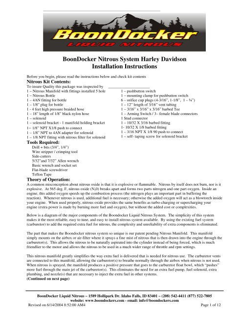
Motorcycle Harley Davidson Nitrous Manual
Motorcycle Harley Davidson Nitrous Manual
Motorcycle Harley Davidson Nitrous Manual
- No tags were found...

Create successful ePaper yourself
Turn your PDF publications into a flip-book with our unique Google optimized e-Paper software.
This manifold is also designed to vary the float bowl pressure in relation to nitrous pressure, thus keeping the nitrous andfuel delivery in sync. Fluctuations in bottle temperature greatly affect nitrous pressure, which affects nitrous delivery. Byautomatically adjusting the fuel delivery as nitrous pressure varies, this manifold makes nitrous safe, reliable, and easy touse.Be sure to understand and follow the tuning instructions at the end of these instructions. Proper tuning is an important partof any performance-enhancing product. +12 V Horn-button switch /solenoid buttonArming Switch(Optional seepage 8)Part I – Bottle InstallationA. Bottle Valve FittingsInsert the 4AN x 1/8” NPT fitting and the 1/8” NPT Plug into the bottle valve (these are attached to the lid of the box forthe bottle). Use Teflon tape to seal the threads – be sure not to gettape inside the threads!B. Bottle Mounting PositionWith nitrous in the bottle, both nitrous liquid and nitrous gas arepresent under high pressure (760psi at 70 deg F). Due to gravity andacceleration forces, the liquid portion of the nitrous will be at thebottom and rearward parts of the bottle. For this nitrous system towork properly, it is important that nitrous liquid be drawn from thebottle. <strong>Nitrous</strong> vapor will cause a significant decrease inperformance.For best results, the bottle should be mounted so the valve is pointeddown and towards the back of the vehicle as shown below, orequipped ! !with an optional siphon tube.Rear ofmotorcyle20 deg to 90Front ofmotorcyclBoonDocker Liquid <strong>Nitrous</strong> – 1589 Hollipark Dr. Idaho Falls, ID 83401 – (208) 542-4411 (877) 522-7805website: www.boondockers.com - email: info@boondockers.comRevised on 6/14/2004 8:52:00 AM4 Page 2 of 12
Dual bottle mounted on front of frame:For some applications, twin 20 oz bottles can be mounted on the frame as shown as shown. Note: because of the restrictedspace and or cosmetics, it is sometimes desirable to mount a 2.5lb aluminum bottle in the Bottle in the Saddlebag.Bottle mounted on front forks:A bracket can be made to install the bottle on the front forks as shown.Stealth install with Bottle mounted in saddle bagC. Bottle Filling /WeightsAutomotive speed shops that sell nitrous kits can usually refill nitrous bottles. This bottle can be filled with non-medicalgrade nitrous oxide that contains a very small amount of sulfur dioxide (combines with water in your lungs and formssulfuric acid if breathed too much), preventing human consumption. This is the same nitrous that is used for all nitrousoxide systems.BoonDocker Liquid <strong>Nitrous</strong> – 1589 Hollipark Dr. Idaho Falls, ID 83401 – (208) 542-4411 (877) 522-7805website: www.boondockers.com - email: info@boondockers.comRevised on 6/14/2004 8:52:00 AM4 Page 3 of 12
Fill the bottle according to the weights below. We do not recommend overfilling the bottle – when the bottle gets hot, itwill rupture the blow-off disk.Note: all weights are in fractions ofpounds, not ounces4.0lbCF2.9lbCF3.0lbALBottle SizeWeight of Cylinder & Gas 7.4 lb 6.0 lb 6.1 lb 6.1 lb 3.0 lb 2.8 lb 2.1 lb 1.7 lbWeight of Cylinder Empty 3.4 lb 3.1 lb 3.1 lb 3.6 lb 1.7 lb 1.8 lb 1.3 lb 1.1 lbWeight of Gas 4.0 lb 2.9 lb 3.0 lb 2.5 lb 1.3 lb 1.0 lb 0.8 lb 0.6 lb2.5lbAL20ozAL16ozAL12ozAL9ozALPart II – <strong>Nitrous</strong> Manifold Installation1. Locate a suitable place on the air cleaner mounting base as shown. Be sure there is adequate room for the 2.5” stem tofit inside. For best results the manifold should spray into the airflow that goes directly to the carburetor(s). <strong>Nitrous</strong>should not be sprayed through the filter.2. Install the manifold to the air cleaner base as shown below.Attach Carburetor vent through existing hole inmounting plate.BoonDocker Liquid <strong>Nitrous</strong> – 1589 Hollipark Dr. Idaho Falls, ID 83401 – (208) 542-4411 (877) 522-7805website: www.boondockers.com - email: info@boondockers.comRevised on 6/14/2004 8:52:00 AM4 Page 4 of 12
+&!%&,-./'*&"#$%& '#() % '"Part III – Solenoid / Hose Installation1. Before installing the following fittings, apply a thread sealant or Teflon tape to the threads – be careful not tocontaminate the insides of these fittings.a. Connect the <strong>Nitrous</strong> Filter to the side of the solenoid marked “IN”.b. Connect the brass compression fitting to the side of the solenoid marked “OUT”.2. Locate the solenoid in or near the air-cleaner base. Use the padded strap to secure the solenoid. The 1/8” black nylonhose going to the manifold and the high-pressure hose from the bottleneeds to easily reach the solenoid with no sharp bends.3. Connect the 1/8” black nylon line from the solenoid brass fitting to thebrass fitting on the nitrous manifold. Keep this away from hot items.Note – do not over tighten the compression fittings!4. Connect the high-pressure braided hose from the bottle to the solenoid.If a universal hose end is included, see the directions below.BoonDocker Liquid <strong>Nitrous</strong> – 1589 Hollipark Dr. Idaho Falls, ID 83401 – (208) 542-4411 (877) 522-7805website: www.boondockers.com - email: info@boondockers.comRevised on 6/14/2004 8:52:00 AM4 Page 5 of 12
Universal Hose End InstallationSome kits come with a hose with one end crimped on and a universal end that is not installed. This allows the hose to becut to length (a hacksaw can be used). Install the end as follows.1. Cut hose to length.2. Clean the hose using compressed air. Make sure there is no debris leftinside the hose.3. Install part A on the hose.4. Install part B so it fits over the innerplastic hose. Press part B on far enoughso the plastic hose stops at the inner lip.5. Push part C onto the hose end.6. Tighten part A and part C together usingwrenches.BoonDocker Liquid <strong>Nitrous</strong> – 1589 Hollipark Dr. Idaho Falls, ID 83401 – (208) 542-4411 (877) 522-7805website: www.boondockers.com - email: info@boondockers.comRevised on 6/14/2004 8:52:00 AM4 Page 6 of 12
Part IV - Carb Vent to <strong>Nitrous</strong> Manifold InstallationThe nitrous manifold must be able to pressurize the carb float bowl andthe carb vent lines must be able to drain if fuel gets trapped in the lines.01& Connect the carb vent lines to the nitrous manifold as follows. Spliceinto the carb vent line with a Tee and run a line from the Tee to thenitrous manifold. Put orifice cup plugs in the bottom of all vent lines –the .025” orifice will allow fuel to drain, but retain pressure to the floatbowl.Refer to the diagrams below for ideas.A. Crab. has two vents and one drainCarb. Vent – connectto <strong>Nitrous</strong> Manifold0/& !-<strong>Nitrous</strong> manifoldCarb.Tee – only required if vent line hangsbelow float bowl where fuel can gettrapped, insert a tee and a drain atlowest point to allow trapped fuel todrain out.Drain lines – insertorifice cup plugs hereA. Carb. has one vent and one drainCarb. Vent – connectto <strong>Nitrous</strong> Manifold<strong>Nitrous</strong> manifoldCarb.T line and insert orificecup plug hereBoonDocker Liquid <strong>Nitrous</strong> – 1589 Hollipark Dr. Idaho Falls, ID 83401 – (208) 542-4411 (877) 522-7805website: www.boondockers.com - email: info@boondockers.comRevised on 6/14/2004 8:52:00 AM4 Page 7 of 12
Detail of Air-cleaner base and manifold mount with t’s and orifice plugsPart IV – Push-Button InstallationThe pushbutton switch can be attached to the left handlebar with the clamp provided or wired to the horn with the armingswitch supplied.Part V – Electrical InstallationConnect the connector plug to the switch and solenoid according to the following diagram.+Solenoid12v DCHorn_Arming ButtonSwitchNote: + and –connections canbe wired eitherwayBoonDocker Liquid <strong>Nitrous</strong> – 1589 Hollipark Dr. Idaho Falls, ID 83401 – (208) 542-4411 (877) 522-7805website: www.boondockers.com - email: info@boondockers.comRevised on 6/14/2004 8:52:00 AM4 Page 8 of 12
Part VII - Startup and Tuning ProceduresA. Important Notes before using <strong>Nitrous</strong>:1. Be sure to use filtered nitrous – always use a filter when filling your bottle!2. When tuning the system, do not use nitrous for more than 2 seconds at a time. Once the system is properly tuned (seesteps below), we recommend not using nitrous for more than 8 seconds at a time. If nitrous is used for longer durations,it is critical that the system be carefully tuned and that no detonation problems are occurring.B. Startup & Leak Test ProcedureThe rider must do the following steps every time the bottle is turned on and before doing the fuel adjustment procedure.1. With the engine off, open the bottle valve and check for leaks. Shut the bottle valve off. With the valve shut, thehose will still have pressure in it.2. With pressure in the hose and the bottle valve closed, start the engine. Check to make sure the solenoid does notdischarge hose pressure.3. With the engine running (be ready to shut down engine if necessary), open the bottle valve. Push the nitrous buttonfor about one second or less. In most cases the engine rpm should increase if the nitrous system is functioningproperly. Some carburetors may get too much fuel if the nitrous is sprayed at an idle – this will cause the engine tobegin to flood and rpms may drop in this case. If the solenoid is not functioning, recheck the electrical connectionsand voltages and repeat this procedure.D. <strong>Nitrous</strong> Manifold Fuel Adjustment ProcedureThere is a fuel adjustment screw on the nitrous manifold. This screw adjusts the amount of fuel when nitrous is being used- it does not add fuel off nitrous. The “R” marking stands for “Rich” – turning the adjustment screw in (clockwise) willadd more fuel when using nitrous.Warning: Only adjust the fuel mixture screw on the <strong>Nitrous</strong> Manifold according to the steps below.The factory setting should provide a starting baseline. Each nitrous manifold requires a different number of turns on thefuel adjustment screw to make a given pressure to the float bowls. We recommend you first count the number of turns ineach screw is set at before making adjustments. This will provide a baseline you can return to if necessary. If this settingaccidentally gets changed and the initial setting is unknown, turn the screw in (clockwise) all the way and then back out 1.5turns, then proceed with the steps below.The steps below should be done with a full nitrous bottle that is at the proper operating temperature (70-90deg F). Makesure the engine is at normal operating temperature. Do not exceed 2 seconds of nitrous use until the fuel adjustment iscomplete and correct.An experienced tuner should only perform this adjustment process. If you are not an experienced tuner, find someone whois. Remember, safety first!1. Run the bike in an open area at full throttle and apply nitrous for 1 or 2 seconds. Note engine power and rpmswhen the button is pushed.BoonDocker Liquid <strong>Nitrous</strong> – 1589 Hollipark Dr. Idaho Falls, ID 83401 – (208) 542-4411 (877) 522-7805website: www.boondockers.com - email: info@boondockers.comRevised on 6/14/2004 8:52:00 AM4 Page 9 of 12
2. Enrich the mixture by turning the nitrous manifold adjustment screw in (clockwise) 1/2 turn. Run nitrous for 1 or2 seconds again and note power and rpm difference. If no power loss is noted, repeat step 2 until a loss is noted.A power loss indicates you are rich enough (be sure!) - go to step 3.3. To find where the mixture starts to become too lean, turn the nitrous manifold adjustment screw out(counterclockwise) 1/2 turn and note power. A power increase should be noted. Turn nitrous manifoldadjustment out 1/2 turn and compare to previous run. If no power increase is noted, go to step 4. If powerincrease is noted, repeat step 3 until no power increase is noted. Use extreme caution - you can go too lean!4. For the final setting, turn the nitrous manifold adjustment screw back in (clockwise) 1/2 turn.5. After this adjustment is made, if the engine does not run perfectly smooth when using nitrous, do not use it! If theexhaust note does not sound clean, the cause is likely detonation, which can quickly destroy the engine.Part VIII – Adjusting Amount of <strong>Nitrous</strong>It is possible to increase/decrease the amount of nitrous the nitrous manifold sprays by replacing the ¾” nozzles withnozzles with more/less orifice holes. In general, each orifice hole that is sprayed is equivalent to a 3-5hp increase.Read this before you increase nitrous!Be sure your engine is working well before you decide to increase the amount of nitrous. If you are not getting the powerincrease you are expecting with the original setup, something is likely wrong. Review the manifold tuning procedure andverify that you can tune the manifold so you know there is too much fuel. From there, if leaning the manifold mixturescrew does not produce an increase in power, one of the following problems may exist:1. Be sure your bottle is full, at the correct temperature (70-90 deg), and positioned correctly so the valve picks up liquidnitrous. The system will not work properly if nitrous vapor is being picked up or if the bottle is too cold.2. Your engine could be detonating. Detonation can occur if your compression ratio is high, your timing has beenadvanced, or you are not using good octane fuel. Listen carefully to the motor - if it does not sound clean and you arenot too rich, you are likely detonating.3. A bad power source or faulty electrical connection may cause the nitrous system to malfunction intermittently.Carefully check all connections. If necessary, solder all connections.4. Dirty nitrous can quickly plug the nitrous filter and obstruct the nitrous delivery. Remove and clean the sintered bronzefilter element by blowing compressed air through it backwards. Always fill your bottle from a filtered source.BoonDocker Liquid <strong>Nitrous</strong> – 1589 Hollipark Dr. Idaho Falls, ID 83401 – (208) 542-4411 (877) 522-7805website: www.boondockers.com - email: info@boondockers.comRevised on 6/14/2004 8:52:00 AM4 Page 10 of 12
Installing / Removing Nozzles1. Remove the nitrous manifold from the air-filter base.2. Use a 7/32” hex wrench to carefully remove/install anozzle. Be sure the o-ring is still in place beforethreading in a new nozzle. Be very careful not to overtighten the plastic nozzle – it needs to be just snug.(!3. If you want to increase nitrous delivery, increase thenumber of nozzle holes by one!4. Retune the nitrous manifold according to the instructionsabove. Anytime the orifices are changed, the nitrousmanifold pressure will change so retuning is necessary.++Part IX – Warranty, Terms & ConditionsReturned Goods – No merchandise will be accepted without prior approval. A RMA number (Return MerchandiseAuthorization) provided by Boondocker is required before a return will be accepted. A 20% handling and restockingcharge will be applied to returned merchandise. No unauthorized returns will be accepted.Limited Warranty – Boondocker warrants its product to the original purchaser against defects in material andworkmanship for a period of 90 days, commencing from the date of product delivery to the Consumer.Maximum Liability – The maximum liability of Boondocker in connection with this warranty shall not under anycircumstances exceed the price of the product claimed to be defective.BoonDocker Liquid <strong>Nitrous</strong> – 1589 Hollipark Dr. Idaho Falls, ID 83401 – (208) 542-4411 (877) 522-7805website: www.boondockers.com - email: info@boondockers.comRevised on 6/14/2004 8:52:00 AM4 Page 11 of 12