MSD Digital Shift Light (PN 89631)
MSD Digital Shift Light (PN 89631)
MSD Digital Shift Light (PN 89631)

You also want an ePaper? Increase the reach of your titles
YUMPU automatically turns print PDFs into web optimized ePapers that Google loves.
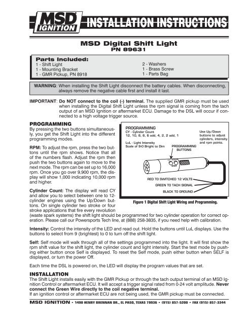
<strong>MSD</strong> <strong>Digital</strong> <strong>Shift</strong> <strong>Light</strong><strong>PN</strong> <strong>89631</strong>Parts Included:1 - <strong>Shift</strong> <strong>Light</strong>1 - Mounting Bracket1 - GMR Pickup, <strong>PN</strong> 89182 - Washers1 - Brass Screw1 - Parts BagWARNING: When installing the <strong>Shift</strong> <strong>Light</strong> disconnect the battery cables. When disconnecting,always remove the negative cable first and install it last.IMPORTANT: Do NOT connect to the coil (-) terminal. The supplied GMR pickup must be usedwhen installing the <strong>Digital</strong> <strong>Shift</strong> <strong>Light</strong> unless the rpm signal is coming from the tachoutput of an <strong>MSD</strong> Ignition or aftermarket ECU. Damage to the DSL will occur if connectedto a high voltage trigger source.PROGRAMMINGBy pressing the two buttons simultaneously,you get the <strong>Shift</strong> <strong>Light</strong> into the differentprogramming modes.RPM: To adjust the rpm, press the two buttonsuntil the rpm shows. Notice that allof the numbers flash. Adjust the rpm thenpush the two buttons again to move to thenext mode. The rpm can be set up to 16,000rpm. Once you go over 9,900 rpm, the displaywill show 1,000 indicating 10,000 rpmand higher.PROGRAMMINGCY - Cylinder Count12, 10, 8, 6, 6 odd, 4, 2, 2 odd, 1LuL - <strong>Light</strong> IntensityScale of 9-0 Bright to DimUPPROGRAMMINGBUTTONSDOWNMODERED TO SWITCHED 12 VOLTSGREEN TO TACH SIGNALUse Up/Downbuttons to adjustcylinders, intensityand rpm points.Cylinder Count: The display will read CYBLACK TO GROUNDand allow you to select between one to 12-cylinder engines using the Up/Down buttons.On single cylinder two stroke or fourFigure 1 <strong>Digital</strong> <strong>Shift</strong> <strong>Light</strong> Wiring and Programming.stroke applications that fire every revolution(waste spark systems) the shift light should be programmed for two cylinder operation for correct operation.Please call our Powersports Tech line, at (888) 258-3835, if you need help with calibration.Intensity: Control the intensity of the LED and read out. Hold the buttons until LuL displays. Use thebuttons to select from 9 (brightest) to 0 to turn off the shift light.Self: Self mode will walk through all of the settings programmed into the light. It will first show therpm shift value for the shift light, the cylinder count and light intensity. Start the test mode by pushingeither button once Self is displayed. To reset the Self mode, push either button when SELF isdisplayed, or turn the power Off.Each time the DSL is powered on, the LED will display the program values that are set.INSTALLATIONThe <strong>Shift</strong> <strong>Light</strong> installs easily with the GMR Pickup or through the tach output terminal of an <strong>MSD</strong> IgnitionControl or aftermarket ECU. It will accept a trigger signal rated from 0-24 volt amplitude. Neverconnect the Green Wire directly to the coil negative terminal.If an ignition control or aftermarket ECU are not being used, the GMR pickup must be connected.<strong>MSD</strong> IGNITION • 1490 HENRY BRENNAN DR., EL PASO, TEXAS 79936 • (915) 857-5200 • FAX (915) 857-3344
REDORANGEMAGNETICCONNECTORNOT USEDBLACK GROUNDBLACKINSTALLATION INSTRUCTIONSWHITEUPDOWNMODECOILGREENSWITCHED12 VOLTREDREDREDORANGEORANGEBLACKBLACKMAGNETICCONNECTORNOT USEDWHITEWHITETRIGGER INPUTBLACKTO BATTERYTO BATTERYFigure 2 Installing with an <strong>MSD</strong> Ignition.GREENREDUPDOWNMODEBLACK GROUNDFigure 3 Installing with an <strong>MSD</strong> Motorcycle Ignition.<strong>MSD</strong> IGNITION • 1490 HENRY BRENNAN DR., EL PASO, TEXAS 79936 • (915) 857-5200 • FAX (915) 857-3344
INSTALLATION INSTRUCTIONSGMR PICKUP INSTALLATIONMETAL TABThe <strong>MSD</strong> GMR pickup can be used with inductiveor capacitive ignition types to provideWASHER MUST BE ON TOP OF METAL TABan rpm signal of 30% duration when the ignitioncoil fires. Two washers are provided withGMR PICKUPthe pickup and must be installed in one of twopositions depending on the type of ignitiondriving the coil. For late model applications, itis recommended to have a wiring schematicPRIMARY COIL (+) WIREof the vehicle’s ignition system. On someFigure 4 Looping Coil Wire.motorcycle and ATV applications, the stockcoils do not produce a long enough pulse. In these cases, loop the coil wire through the GMRpickup twice (Figure 4).BLACK GROUNDUPDOWNCOILHARNESSMODEGREENNote: The shift lightmust be progr a m m e dfor 1-cylinderoperation.SHIFT LIGHTSWITCHED12 VOLTMETAL TABREDGMR PICKUPGMR PICKUPSIGNALOUTPUTGREENBLACK GROUNDNOTE: The brass screw must be used for proper operation.WASHER MUST BE ON TOP OF METAL TABGMR PICKUPCOIL (+)12 VOLTSCOIL (-)TRIGGER 1COIL (-)TRIGGER 2COIL (-)TRIGGER 3IGNITIONCOILIGNITIONCOILIGNITIONCOILCOIL (-)TRIGGER 4PRIMARY COIL (+) WIRE ORDIESEL INJECTOR 12 VOLT WIREIGNITIONCOILFigure 5 Installation on an Inductive Coil-Per-Cylinder Ignition System.BLACK GROUNDPOWERTRAIN CONTROL MODULECOIL HARNESSCOIL (-) 2COIL (+)COIL (-) 1GMR PICKUPUPGREENSIGNALOUTPUTGREENDOWNMODEREDREDSWITCHED12 VOLTNote: The shift lightmust be programmedfortwo (2) cylinderoperation.TRIGGER COIL 2IGNITION 12 VOLTSTRIGGER COIL 1METAL TABBLACK GROUNDNOTE: The brass screw must be used for proper operation.WASHER MUST BE ON TOP OF METAL TABGMR PICKUPGMR PICKUPPRIMARY COIL (+) WIRE ORDIESEL INJECTOR 12 VOLT WIREFigure 6 Installing to an Inductive Coil Pack.<strong>MSD</strong> IGNITION • 1490 HENRY BRENNAN DR., EL PASO, TEXAS 79936 • (915) 857-5200 • FAX (915) 857-3344
TMBLACK GROUNDUPDOWNMODEGREENCHASSISGROUNDSHIFT LIGHTGREENBLACKSWITCHED12 VOLTREDBLACKGROUNDIGNITIONGMR PICKUPREDTO GROUNDON CYLINDERHEADMETAL TABNOTE: The brass screw must be used for proper operation.WASHER MUST BE ON TOP OF METAL TABGMR PICKUPPRIMARY COIL (+) WIRE ORDIESEL INJECTOR 12 VOLT WIRENote: For 12 Amp Pro Mags, connect theGMR Pickup to the Orange wireleading to the kill switch.Figure 7 Wiring the Pro Mag 44 Electronic Points Box.Note: The shift light mustbe programmed for1-cylinder operation.INJECTOR12 VOLT WIRESHIFT LIGHTUP DOWNMODEBLACK GROUNDGREENSIGNALOUTPUTGMR PICKUPGREENREDSWITCHED12 VOLTBLACK GROUNDMETAL TABNOTE: The brass screw must be used for proper operation.WASHER MUST BE ON TOP OF METAL TABINJECTORPOWER WIREGMR PICKUPPRIMARY COIL (+) WIRE ORDIESEL INJECTOR 12 VOLT WIREFigure 8 Installation to a Diesel Injector.ServiceIn case of malfunction, this <strong>MSD</strong> component will be repaired free of charge according to the terms of the warranty. When returning<strong>MSD</strong> components for service, Proof of Purchase must be supplied for warranty verification. After the warranty period has expired,repair service is charged based on a minimum and maximum charge.All returns must have a Return Material Authorization (RMA) number issued to them before being returned. To obtain anRMA number please contact <strong>MSD</strong> Customer Service at (915) 855-7123 or fax a request to (915) 857-3344. Send the unit prepaid withproof of purchase to the attention of: <strong>MSD</strong> Ignition, Customer Service - RMA #, 12120 Esther Lama, Dock 5, El Paso, Texas 79936.When returning the unit for repair, leave all wires at the length in which you have them installed. Be sure to include a detailedaccount of any problems experienced, and what components and accessories are installed on the vehicle.The repaired unit will be returned as soon as possible after receipt, COD for any charges. (Ground shipping is covered by warranty).All units are returned regular UPS unless otherwise noted. For more information, call the <strong>MSD</strong> Customer Service Line (915) 855-7123.<strong>MSD</strong> technicians are available from 7:00 a.m. to 6:00 p.m. Monday - Friday (mountain time).<strong>MSD</strong> IGNITION • 1490 HENRY BRENNAN DR., EL PASO, TEXAS 79936 • (915) 857-5200 • FAX (915) 857-3344© 2006 Autotronic Controls CorporationFRM27591 Created 04/06 Printed In U.S.A.