Multiple Internal Software Config. (MINT) (PDF 2.54MB)
Multiple Internal Software Config. (MINT) (PDF 2.54MB)
Multiple Internal Software Config. (MINT) (PDF 2.54MB)
- No tags were found...

You also want an ePaper? Increase the reach of your titles
YUMPU automatically turns print PDFs into web optimized ePapers that Google loves.
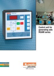
Compact Controller for Stand-by and Parallel Operating Gen-setsInteliGen ®Modular Gen-set Controller<strong>Multiple</strong> <strong>Internal</strong> <strong>Software</strong> <strong>Config</strong>uration - <strong>MINT</strong>IG-CU + IG-PCLSM + IG-AVRi<strong>Software</strong> version IG-6.1, May 2004User guideCopyright © 2004 ComAp s.r.o.Written by Ladislav KadanikPrague, Czech RepublicComAp, spol. s r.o.Světova 7, 180 00 Praha 8, Czech RepublicTel: +420 2 66316661, Fax: +420 2 66316647E-mail: info@comap.cz, www.comap.cz
Table of ContentsTable of Contents ...............................................................................................................................................2General guidelines..............................................................................................................................................5What is described in this manual? .................................................................................................................5!! Warnings !! ..................................................................................................................................................5Text ................................................................................................................................................................5Conformity declaration ...................................................................................................................................5General description ............................................................................................................................................7Description of the controller system (with all options)....................................................................................7<strong>MINT</strong> - required and optional modules...........................................................................................................7Terminals and Dimensions.................................................................................................................................8IG-CU Terminals ............................................................................................................................................8Dimensions...................................................................................................................................................11IGL-RA15 Remote annunciator....................................................................................................................14IG-IB Internet bridge.....................................................................................................................................15Recommended wirings.....................................................................................................................................16IG-IOM Wiring ..............................................................................................................................................18IG-MU Wiring................................................................................................................................................18<strong>Multiple</strong> sets application ...................................................................................................................................20MPM: <strong>Multiple</strong> Prime mover .........................................................................................................................20MSB: <strong>Multiple</strong> Stand-by................................................................................................................................22<strong>Multiple</strong> Parallel to mains, Stand-by, no MCB synchronization ...................................................................24<strong>Multiple</strong> Parallel to mains, Stand-by, MCB synchronized, short time parallel..............................................25<strong>Multiple</strong> Parallel to mains, Stand-by, MCB synchronized, Import-Export power or Base load control inparallel to mains + Stand-by ........................................................................................................................28Getting started ..................................................................................................................................................30How to install................................................................................................................................................30Analog inputs - configuration........................................................................................................................36Hardware connection ...................................................................................................................................38Extension modules (CAN bus) connection ..................................................................................................43Inputs and outputs ............................................................................................................................................45Binary inputs IG–CU + IG-PCLSM default..............................................................................................45Binary inputs IG-IOM, IGS-PTM default....................................................................................................45Binary inputs – list ........................................................................................................................................46Binary outputs IG-CU+IG-PCLSM default...................................................................................................49Binary outputs IG-IOM, IGS-PTM ...............................................................................................................49Binary outputs – list......................................................................................................................................49Analog inputs IG-CU (+IG-IOM or IGS-PTM)...............................................................................................56Analog output IG-IOM, IGS-PTM ................................................................................................................56Setpoints...........................................................................................................................................................57Password......................................................................................................................................................57Process control ............................................................................................................................................58Basic settings ...............................................................................................................................................58Engine params .............................................................................................................................................60Engine protect ..............................................................................................................................................63Gener protect ...............................................................................................................................................66Pwr management .........................................................................................................................................70Sync/Ld ctrl...................................................................................................................................................74Volt/PF ctrl....................................................................................................................................................77Act. calls/SMS ..............................................................................................................................................79Load Shedding .............................................................................................................................................80Date and time...............................................................................................................................................80Sensor spec .................................................................................................................................................81IM - IG <strong>MINT</strong> setpoints adjustment...................................................................................................................82Active and reactive power terminology ........................................................................................................82Steps of InteliGen <strong>MINT</strong> set points adjustment............................................................................................83InteliGen – <strong>MINT</strong>, SW version 6.1, ©ComAp – May 2004 2 -IG-<strong>MINT</strong>-<strong>MINT</strong>+IOM-6.1.<strong>PDF</strong>
Steps of InteliMains set points adjustment...................................................................................................88Sensor specification .........................................................................................................................................92Sensor calibration ........................................................................................................................................92Default sensor settings.................................................................................................................................92Operator Interface ............................................................................................................................................94Pushbuttons and LEDs ................................................................................................................................94How to select gen-set mode ?......................................................................................................................95When to use GCB ON/OFF button ? .........................................................................................................95Display menus..............................................................................................................................................95How to view measured data?.......................................................................................................................95How to view and edit set points? .................................................................................................................95How to view the HISTORY menu?...............................................................................................................96How to find active alarms ? ..........................................................................................................................96Description of MEASUREMENT screens ....................................................................................................96Flow Chart of pushbutton Operation ............................................................................................................99Mode description ............................................................................................................................................101OFF mode ..................................................................................................................................................101MAN mode .................................................................................................................................................101AUT mode ..................................................................................................................................................101Load surge protection ................................................................................................................................102Load shedding............................................................................................................................................102Alarm management ........................................................................................................................................105Warning......................................................................................................................................................105Unload ........................................................................................................................................................105Slow stop....................................................................................................................................................105Shut down ..................................................................................................................................................106Voltage phase sequence detection............................................................................................................106Setpoint replication management...................................................................................................................110How to adjust setpoints ..............................................................................................................................110Setpoints consistency ................................................................................................................................110Gen-set operation states ................................................................................................................................111Start-stop sequence ...................................................................................................................................111Unsuccessful start......................................................................................................................................112Remote control and data logging ...................................................................................................................113Direct connection to the PC .......................................................................................................................113PC software - WinEdit ................................................................................................................................113History file...................................................................................................................................................113Remote and mobile communication ...............................................................................................................117Modbus protocol.........................................................................................................................................117Recommended ISDN modem ....................................................................................................................117Recommended GSM modem.....................................................................................................................117SIM card setting .........................................................................................................................................118Active SMS message .................................................................................................................................118IG-IB Internet communication ...................................................................................................................119Value and setpoints codes .............................................................................................................................120Technical data ................................................................................................................................................126Power supply..............................................................................................................................................126Operating conditions ..................................................................................................................................126Dimensions and weight ..............................................................................................................................126Bus and generator......................................................................................................................................126IG-MTU.......................................................................................................................................................127IG-MTU-C...................................................................................................................................................127Binary inputs and outputs...........................................................................................................................127Analog inputs..............................................................................................................................................127Speed pick-up input ...................................................................................................................................128CAN bus interface ......................................................................................................................................128IG-PCLSM..................................................................................................................................................129IG-AVRi ......................................................................................................................................................129IG-IOM........................................................................................................................................................129IG-MU.........................................................................................................................................................130IG-IB ...........................................................................................................................................................130InteliGen – <strong>MINT</strong>, SW version 6.1, ©ComAp – May 2004 3 -IG-<strong>MINT</strong>-<strong>MINT</strong>+IOM-6.1.<strong>PDF</strong>
IGS-PTM ....................................................................................................................................................130IGL-RA15 ...................................................................................................................................................131InteliGen Low Temperature modification ..................................................................................................131InteliGen – <strong>MINT</strong>, SW version 6.1, ©ComAp – May 2004 4 -IG-<strong>MINT</strong>-<strong>MINT</strong>+IOM-6.1.<strong>PDF</strong>
General guidelinesWhat is described in this manual?This manual describes „<strong>MINT</strong>“ software configuration. The software configuration is designed for multiplesets applications with InteliGen internal load sharer and synchronizer (IG-PCLSM interface).What is the purpoase of this manual?This manual provides general information on how to install and operate the InteliGen controller.This manual is intended for use by:Operators of gen-setsGen-set control panel buildersFor everybody who is concerned with installation, operation and maintenance of the gen-set!! Warnings !!Remote controlInteliGen controller can be remotely controlled. In the event that maintenance needs to be done to the genset,check the following to ensure that the engine cannot be started.To be sure:Disconnect remote control via RS232 lineDisconnect input REMOTE START/STOPorDisconnect output STARTER and output GCB CLOSE/OPENThe InteliGen contains a large number of configurable setpoints, because of this it is impossible to describeall applications. InteliGens functions are subject to change from SW version to SW version. This manual onlydescribes the product and is not guaranteed to be set for your application on arrival.TextPAGEBreak ReturnGenerator protectionsREMOTE START/STOP(Capital letters in the frame) buttons on the front panel(Italic) set points(Bold) Set point group(Capital letters) binary inputs and outputsConformity declarationFollowing described machine complies with the appropriate basic safety and healthrequirement of the EC Low Voltage Directive No: 73/23 / EEC and ECElectromagnetic Compatibility Directive 89/336 / EEC based on its design and type,as brought into circulation by us.InteliGen – <strong>MINT</strong>, SW version 6.1, ©ComAp – May 2004 5 -IG-<strong>MINT</strong>-<strong>MINT</strong>+IOM-6.1.<strong>PDF</strong>
Note:ComAp believes that all information provided herein is correct and reliable and reserves the right to updateat any time. ComAp does not assume any responsibility for its use unless otherwise expressly undertaken.WARNING – VERY IMPORTANT !!!Be aware that the binary outputs can change state during and after softwarereprogramming (before the controller is used again ensure that the properconfiguration and setpoint settings are set in the controller)!!!Be aware that gen-set can automatically or remotely start !!!Switch InteliGen to MAN mode and disconnect the Binary outputs Starter and Fuel toavoid unexpected automatic start of genset and GCB closing.Dangerous voltage!!! CAUTION !!!The terminals for voltage and current measurement should never be touched.Properly connect the grounding terminals.Do not disconnect the InteliGens CT terminals for any reason.Adjust set pointsAll parameters are preadjusted to their typical values. But the set points in the “Basic settings” settingsgroup !!must!! be adjusted before the first startup of the gen-set.!!! WRONG ADJUSTMENT OF BASIC PARAMETERSCAN DESTROY THE GEN-SET !!!The following instructions are for qualified personnel only. To avoid personal injury donot perform any action not specified in this User guide !!!InteliGen – <strong>MINT</strong>, SW version 6.1, ©ComAp – May 2004 6 -IG-<strong>MINT</strong>-<strong>MINT</strong>+IOM-6.1.<strong>PDF</strong>
General descriptionDescription of the controller system (with all options)InteliGen IG-CU is a comprehensive AMF-controller for single and multiple generating sets operating instand-by or parallel modes. A modular construction allows upgrades to different levels of complexity in orderto provide the best solution for various customer applications. Optional synchronizer, isochronous loadsharer, Mains and Generator protections allows for a total integrated solution for Gen-sets in stand-by andparallel modes with multiple engine support.InteliGen controllers are equipped with a powerful graphic display showing icons, symbols and bar-graphsfor intuitive operation, which sets, together with high functionality, new standards in Gen-set controls.The InteliGen automatically starts the gen-set, closes the Gen-set C.B. when all conditions are met, thenstops the engine on external signal or by pressing push buttons.With upgrade kits, isolated parallel and parallel to Mains operation can be achieved. Forward and reversesynchronizing, Mains protection including load surge, load and power factor control, earth fault protection arethe major functions provided. Interfacing to foreign synchronizers and load sharers is supported.The key feature of InteliGen is its easy-to-use operation and installation. Predefined configurations fortypical applications are available as well as user-defined configurations for special applications.<strong>MINT</strong> - required and optional modulesAccessories Description Standard / OptionalIG-CU InteliGen central unit StandardIG-PCLSM InteliGen power control and load sharing module StandardAT LINK-CABLE RS232 (WinEdit) communication cableOptional1,8mIG-MTUIG-MTU-CInteliGen voltage transformer unit to separatemains and generator voltage measurement (C =with filter)OptionalIG-AVRI InteliGen AVR interface OptionalIG-AVRi-TRANS InteliGen voltage transformer for supplying AVRi OptionalmoduleIG-COM InteliGen communication unit OptionalIG-MU InteliGen – Modem Unit OptionalIG-IB Internet bridge OptionalIGL-RA15 Remote annunciator OptionalIGS-PTM orIG-IOMExternal analog, binary I/O unit.Connecting 3m cable is part of module delivery.OptionalInteliGen display software descriptionSerial number Descriptionxx1xxxxx Standard character set: part of ASCII code (less than 128)xx2xxxxx Standard character set: + West European languages*xx3xxxxx Standard character set: + Chinese charactersxx4xxxxx Standard character set: + West & East European languages incl. Russianxx5xxxxx Standard character set: + West & East European languages incl. TurkishInteliGen – <strong>MINT</strong>, SW version 6.1, ©ComAp – May 2004 7 -IG-<strong>MINT</strong>-<strong>MINT</strong>+IOM-6.1.<strong>PDF</strong>
Terminals and DimensionsIG-CU TerminalsGrounding TerminalGENERATOR CURRENT0 - 5 AGENERATOR VOLTAGE3 x 230 / 400 VBINARY INPUTSEXTENSION MODULESiG-COM / iG-IOMEXTENSION MODULESiG-PCM / iG-PCLSMRS 232LB 5L1kL1lL2kL2lL3kL3lNL1L2L3L1L2L3BI1BI2BI3BI4BI5BI6BI7BI8BI9iG-CUBOOT JUMPERInl In (Im L3)Ink CURRENTANALOG INPUTSCOMAI1 (OIL)AI2 (TEMP)AI3 (FUEL)RPM GNDRPMRPM INBO1(START)BO2(FUEL)BO3BINARY OUTPUTSBO4BO5BO6BO7BO8BO9POWER8 - 36 V DC+ -RPM Grounding TerminalDrawing text translationGrounding TerminalRPM Grounding TerminalIG-PCLSM TerminalsShieldLSM+GNDVoutRVoutLSM-AVRi-AVRi+BI10LB 4LOADSHARINGSPEEDGOVERNORAVRiBINARYINPUTSBI11BI12BI13BO10BINARYOUTPUTSBO11BO12BO13POWER8 - 36 V DC+ -Warning !!!Switch IG-CU off before connecting IG-PCLSM !InteliGen – <strong>MINT</strong>, SW version 6.1, ©ComAp – May 2004 8 -IG-<strong>MINT</strong>-<strong>MINT</strong>+IOM-6.1.<strong>PDF</strong>
IG-AVRi TerminalsAVRi -AVRi +LB 4OUT1GNDOUT2AC1AC2IG-COM TerminalsThere is different wiring of IG-COM CAN connectors from hardware version 4.0.The IG-COM label is from side.HCOMLCOMLHCAN 2 EXTENSION MODULE CAN 1CAN R 120ΩiG-COMLB 4Green CAN connectors are separated:CAN2CAN2 = inter-controller CAN,- galvanically separated- internal resistor 120 ohm via jumperCAN1CAN1 = for extension modules- IG-IOM, IGS-PTM, IGL-RA15, …- connection to Extension module 9 pinconnector:CAN H = pin 5CAN L = pin 9IG-MU TerminalsLCOMHLCOMHCAN CANRS 422 LB 6TxBTxARxBRxACOMRS 485RS 232iG-MURS 485 / RS 422RS 232POWER8-36V DCIndication LED:TxCAN, RxCANTxD, RxDRUNIndicates data transfer on the CAN2 line.Indicates data transfer on the RS232 line.Lights when at least one other unit is active on the CAN2 bus.Blinks when no unit is communicated on the CAN2 bus.InteliGen – <strong>MINT</strong>, SW version 6.1, ©ComAp – May 2004 9 -IG-<strong>MINT</strong>-<strong>MINT</strong>+IOM-6.1.<strong>PDF</strong>
PWRLights All time when power supply is switched on.Hint:It is recommended to use IG-MU software 2.2 for IG-6.1.<strong>Internal</strong> IG-MU jumpersP4P1P2P3P1 … 2-nd local bridgeP2 … Modbus jumperP3 … Boot jumperP4 … Switch between RS232 and RS485/RS422IG IOM, IGS-PTM terminalsIGS-PTM is modification of standard IG-IOM module with four analog inputs, which can be configured forrange:• 0 – 250 Ω (suitable for Pt100, Ni100),• 0 – 100 mV (suitable for thermocouples),• 0 – 20 mA.IGS-PTM can be connected to IG-CU or IS-CU. Detail description see in IGS-PTM manual.BI1BO 1BI2BO 2BI3BO 3BI4BI5BI6BI7BINARY INPUTS ANALOG INPUTS ANALOG OUTIG-CUBIN ARY O UTPUTSBO 4BO 5BO 6BO 7BO 8 BI8iG-IOMCOMAI4RS232PO WER8-36V DCHint:IG-IOM, IGS-PTM power supply indication LED :lights when power supply is in the rangeInteliGen – <strong>MINT</strong>, SW version 6.1, ©ComAp – May 2004 10 -IG-<strong>MINT</strong>-<strong>MINT</strong>+IOM-6.1.<strong>PDF</strong>
links when there is no communication between IG-CU and IG-IOM, IGS-PTMDimensionsIG-CU + IG-COM + IG-PCLSM130 (5,1")123 (4,8")2113 (4,4")1~ 130 (5,1")1170 (8,87")2~ 110 (4,3")80 (3,1")iG-PCLSMiG-CUiG-COM24(0,9")42,5 (1,7")45 (1,8")185 (7,3")1. RS 232 Cable must be ordered separately, order code: AT LINK-CABLE 1,8m.2. IG-IOM or IGS-PTM (3m) cable is part of module delivery.Cutout for InteliGen 113 x 175 mm (4,4 x 6,9”).IG-AVRi, IG-AVRi TRANS/LVPrimary terminals50 / 60 HzOUT1GNDOUT2AC1AC20 - 230/277 - 400/480LB 4AVRi -AVRi +iG-AVRiTRANS/LV36 (1,4”)0 - 1843 (1,7”) 43 (1,7”)Secondary terminalsInteliGen – <strong>MINT</strong>, SW version 6.1, ©ComAp – May 2004 11 -IG-<strong>MINT</strong>-<strong>MINT</strong>+IOM-6.1.<strong>PDF</strong>
IG-AVRi unit is DIN rail mount (35mm)IG-AVRi TRANS are DIN rail mount (35mm)IG-MU96 mm (3,8´´)95 mm(3,7´´)43 mm(1,7´´)IG-MU unit is DIN 35 mm rail mounted.IG-IOMBI1BO1BI2BO2BI3BO3BI4BI5BI6BI7BINARY INPUTS ANALOG INPUTS ANALOG OUTIG-CUBINARY OUTPUTSBO4BO5BO6BO7BO8 BI8iG-IOMCOMAI4RS232POWER8-36V DC96 mm (3,8´´)95 mm(3,7´´)IG-IOM unit is DIN 35 mm rail mounted.43 mm(1,7´´)InteliGen – <strong>MINT</strong>, SW version 6.1, ©ComAp – May 2004 12 -IG-<strong>MINT</strong>-<strong>MINT</strong>+IOM-6.1.<strong>PDF</strong>
IGS-PTMBI1BI2BI3BI4BI5BI6BI7BINARY INPUTSBI8GNDANALOG INPUTSAI4AO+AO-0-20 mAANALOG OUTTxRxCANCOMPENSATIONiGS-PTMLCANH COMLB 496 mm (3,8´´)BINARY OUTPUTSPOWERBO1BO2BO3BO4BO5BO6BO7BO88-36V DC95 mm(3,7´´)IGS-PTM unit is DIN 35 mm rail mounted.43 mm(1,7´´)IG-IOM, IGS-PTM is DIN rail mount (35mm).IG-IOM, IGS-PTM is connected to IG-CU by standard IOM cable (3 meters length).Wiring between IGS-PTM or IG-IOM and IG-CU:InteliGen – <strong>MINT</strong>, SW version 6.1, ©ComAp – May 2004 13 -IG-<strong>MINT</strong>-<strong>MINT</strong>+IOM-6.1.<strong>PDF</strong>
IG-IB Internet bridge1 2ETHERNETRJ 45LB 5MODEM / IB CONFIGiG-IBIG-CU / DONGLE96 mm (3,8´´)3 4 5 6H COM LCANPOWER 8 - 36 V DC95 mm(3,7´´)43 mm(1,7´´)It is recommended to use IG-IB firmware version 2.0IG-IB unit is DIN 35 mm rail mounted.See Internet communicationInteliGen – <strong>MINT</strong>, SW version 6.1, ©ComAp – May 2004 15 -IG-<strong>MINT</strong>-<strong>MINT</strong>+IOM-6.1.<strong>PDF</strong>
L3L2L1L3L2L1NRecommended wiringsLOADMGCBSYSTEMSTART/ STOPModem or PCPERS-232CInterfaceCONTROLSIGNALSL1L2L3NGEN C.B. FEED-BACKLOAD RESERVESYST START / STOPEMERG STOPSD OIL PRESSACCESS LOCKSD WATER TEMPSD FUEL LEVELBI1BI2BI3BI4BI5BI6BI7BI8BI9BINARY INPUTSEXTENSION MODULESiG-PCM / iG-PCLSMRS 232BINARY OUTPUTSPOWER8 - 36 V DC+ -BO3BO4BO5BO6BO7BO8BO9GEN C.B.LOAD RES. OKUNLOADHORNPRESTARTSYNCHRONISESYST READY+24VFIX CONFIGURABLEBINARY OUTPUTSGenerator C.B.iG - CUBO1STARTBO2FUELSTARTERFUEL SOLENOIDL1kL1lL2kL2lL3kL3lGENERATORCURRENT0 - 5 AGENERATORVOLTAGE3 x 230 VSerial No.EXTENSION MODULESiG-COM / iG-IOMANALOG INPUTSRPMI lI knnCOMAI1 OILAI2 TEMPAI3 FUELRPM GNDRPM INGGENERATORGRPMCANCANLHCOMCANEXTENSION MODULEiG-COM Serial No.HCOMLDIESEL/GAS ENGINEWATER TEMPOIL PRESSUREFUEL LEVELFUEL SOLENOIDSTARTER- +BATTERYHint:Maximal inductive load of contact relay outputs BO1 and BO2 is 4 Amps. Use external relays for higher load.Drawing text translationDiesel / Gas engineGeneratorInteliGen – <strong>MINT</strong>, SW version 6.1, ©ComAp – May 2004 16 -IG-<strong>MINT</strong>-<strong>MINT</strong>+IOM-6.1.<strong>PDF</strong>
LoadIG-PCLSMiG - PCLSMShieldLSM+LOADSHARINGGNDVoutRVoutSPEEDGOVERNORLSM-AVRi-AVRi+AVRiLB 2LOAD SHARING PARALLEL LINE+-18 V AC18 ViG-AVRiTRANS230/400 VSPEEDGOVERNORAUTOMATICVOLTAGEREGULATOR230/400 VFROM GENERATORSerial No.BI10BINARYINPUTSBI11BI12BI13BINARYOUTPUTSBO10BO11BO12BO13POWER8 - 36 V DC+ -0 V D C0 V D CCONFIGURABLEDrawing text translationSpeed GovernorAutomatic Voltage ControlInteliGen – <strong>MINT</strong>, SW version 6.1, ©ComAp – May 2004 17 -IG-<strong>MINT</strong>-<strong>MINT</strong>+IOM-6.1.<strong>PDF</strong>
Load sharing parallel line<strong>Config</strong>urableIG-IOM Wiring0 V D C0-20mABI1BO 1BI2BO 2BI3BO 3BI4BI5BI6BI7BINARY INPUTSIG-CUBINARY O UTPUTSBO 8 BI8iG-IOMBO 4BO 5BO 6BO 7COMAI4ANALOG INPUTSRS232ANALOG OUTPOWER8-36V DC0 V D C8 - 36 V DCHint:Analog inputs COM terminal has to be connected to minus power supply.IG-MU WiringRS485 / RS 422 connectionIG-MUTxBTxARxBRxABARS485IG-MUTxBTxARxBRxARS422InteliGen – <strong>MINT</strong>, SW version 6.1, ©ComAp – May 2004 18 -IG-<strong>MINT</strong>-<strong>MINT</strong>+IOM-6.1.<strong>PDF</strong>
More IG-MU on CAN busIt is possible to connect two IG-MU units for MultiEdit, WinEdit connection (local bridge) and one IG-MU formodem connection (=maximal three IG-MU) to CAN bus at once.<strong>Internal</strong> address setting jumper must be placed when two local bridges are connected to CAN bus.IG-MU automatically detects modem connection.InteliGen – <strong>MINT</strong>, SW version 6.1, ©ComAp – May 2004 19 -IG-<strong>MINT</strong>-<strong>MINT</strong>+IOM-6.1.<strong>PDF</strong>
<strong>Multiple</strong> sets applicationMPM: <strong>Multiple</strong> Prime moverLOAD3xGCB13xG 1SYS START/STOPMASTER SELECT3xUB3xUG3xI GiG-CUiG-COMiG-PCLSMCANAVRiVoutLSMiG-AVRiAVRiOUTSPEEDGOVERNORLOAD SHARING LINEAVRMASTER SELECTORGCB23xG 23xU B3xUG3xI GCANiG-AVRiAVRSTART/STOPSYS START/STOPMASTER SELECTiG-CUiG-COMiG-PCLSMAVRiVoutLSMAVRiOUTSPEEDGOVERNORLOAD3xMGCBGCB13x3xG 1MGCBRES.OK.(1)RES.OK.(2)MGCBSYS START/STOPMASTER SELECTLOAD RESERVE 23xU B3xUGiG-CU3xI GiG-COMiG-PCLSMCANAVRiVoutLSMiG-AVRiAVRiOUTSPEEDGOVERNORLOAD SHARING LINEAVRMASTER SELECTOR3xMGCBGCB23xG 23xU B3xU G3xI GCANiG-AVRiAVRSTART/STOPSYS START/STOPMASTER SELECTLOAD RESERVE 2iG-CUiG-COMiG-PCLSMAVRiVoutLSMAVRiOUTSPEEDGOVERNORInteliGen – <strong>MINT</strong>, SW version 6.1, ©ComAp – May 2004 20 -IG-<strong>MINT</strong>-<strong>MINT</strong>+IOM-6.1.<strong>PDF</strong>
Drawing text translationLoadSpeed governorMGCBGCBLoad sharing lineSys Start/StopMaster selectLoad reserve 2Master selectorStart/StopCANRes. OKSpecification• MGCB support• Gen-sets unload in island parallel• Power management (if IG-COMs are installed)Hardware requirementsnxnxnxnxIG-CUIG-COM (Optional)IG-PCLSMIG-AVRi, IG-AVRi-TRANS (Optional)Description without MGCB1) Start/Stop switch starts engines in Power management mode by closing of SYS START/STOP input.2) MASTER SELECT selects the gen-set priority regardless of the Priority setpoint, if needed.Description with MGCB1) Start/Stop switch starts engines in Power management mode by closing of SYS START/STOP input.2) LOAD RESERVE 2 is controlled by MGCB, to differentiate the load reserve necessary before closing ofMGCB (setpoints LoadRes Strt 2 and LoadRes Stp 2), and load reserve when system is loaded(setpoints LoadRes Strt 1 and LoadRes Stp 1).3) MGCB is closed by LOAD RES OK of 1 st or 2 nd gen-set and then held by MGCB feedback. Loss ofvoltage at the bus opens MGCB.4) MASTER SELECT selects the gen-set priority regardless of the Priority setpoint, if needed.Hint:Set SysAMFstrt del and SysAMFstp del setpoints at 1s for fast responseInput MCB FEEDBACK should not be configuredInteliGen – <strong>MINT</strong>, SW version 6.1, ©ComAp – May 2004 21 -IG-<strong>MINT</strong>-<strong>MINT</strong>+IOM-6.1.<strong>PDF</strong>
MSB: <strong>Multiple</strong> Stand-byLOADTU,f3xMCB3xGCB13x3x3xG 1U,f3x(3.PH.RELAY)3xU B3xU G3xI GCANiG-AVRiAVRKAMGCMCBKASYS START/STOPMASTER SELECTiG-CUiG-COMiG-PCLSMAVRiVoutLSMAVRiOUTSPEEDGOVERNORLOAD SHARING LINEMASTER SELECTORGCB23xG 23xU B3xU G3xI GCANiG-AVRiAVRU,fSYS START/STOPMASTER SELECTiG-CUiG-COMiG-PCLSMAVRiVoutLSMAVRiOUTSPEEDGOVERNORLOADTU,f3xMCB3xMGCBGCB13x3x3x3xG 1U,fMGCBMCBMCBMGCBRES.OK.(1)RES.OK.(2)MGCBSYS START/STOPMASTER SELECTLOAD RESERVE 23xU B3xU GiG-CU3xI GiG-COMiG-PCLSMCANAVRiVoutLSMiG-AVRiAVRiOUTSPEEDGOVERNORLOAD SHARING LINEAVRMASTER SELECTORMGCB3xGCB23xG 23xU B3xU G3xI GCANiG-AVRiAVRU,fSYS START/STOPMASTER SELECTLOAD RESERVE 2iG-CUiG-COMiG-PCLSMAVRiVoutLSMAVRiOUTSPEEDGOVERNORDrawing text translationLoadSpeed governorInteliGen – <strong>MINT</strong>, SW version 6.1, ©ComAp – May 2004 22 -IG-<strong>MINT</strong>-<strong>MINT</strong>+IOM-6.1.<strong>PDF</strong>
MCBMGCBGCBLoad sharing lineSys Start/StopMaster selectLoad reserve 2Master selectorCAN3.PH.RELAYRes. OKSpecification• Automatic start-up when the mains fails• Reclosing MCB after mains returns• MGCB support• Gen-sets unload in island parallel• Power management (if IG-COMs are installed)Hardware requirements1xnxnxnxnxUf↑↓ relay (Mains decoupling relay) unit + MCB controlIG-CUIG-COM (Optional)IG-PCLSMIG-AVRi, IG-AVRi-TRANS (Optional)Description without MGCB1) The Uf↑↓ relay opens MCB after the mains fails. At the same time the Uf↑↓ relay starts Powermanagement by closing of SYS START/STOP input2) When mains returns, Uf↑↓ relay opens SYS START/STOP and GCBs are opened.3) Bus 3 phase voltage relay detects no voltage and with its time delay closes MCB4) MASTER SELECT selects the gen-set priority regardless of the Priority setpoint, if needed.Description with MGCB1) The Uf↑↓ relay opens MCB after the mains fails. At the same time the Uf↑↓ relay starts Powermanagement by closing of SYS START/STOP input.2) LOAD RESERVE 2 is controlled by MGCB, to differentiate the load reserve necessary before closing ofMGCB (setpoints LoadRes Strt 2 and LoadRes Stp 2), and load reserve while system is loaded(setpoints LoadRes Strt 1 and LoadRes Stp 1).3) MGCB is closed by LOAD RES OK of 1 st or 2 nd gen-set and then held by MGCB feedback.4) When mains returns, Uf↑↓ relay opens SYS START/STOP. Loss of voltage at the bus opens MGCB.5) Bus 3 phase voltage relay detects no voltage and with its time delay closes MCB.6) MASTER SELECT selects the gen-set priority regardless of the Priority setpoint, if needed.Hint:Setpoint SysAMFstrt del is used for engines start delay after the mains fails. It is similar to setpointEmergStart del in Single Stand-by.Setpoint SysAMFstp del is used for GCB opening after the mains returns. It is similar to setpoint Mains Retdel in Single Stand-by.Input MCB FEEDBACK should not be configuredInteliGen – <strong>MINT</strong>, SW version 6.1, ©ComAp – May 2004 23 -IG-<strong>MINT</strong>-<strong>MINT</strong>+IOM-6.1.<strong>PDF</strong>
<strong>Multiple</strong> Parallel to mains, Stand-by, no MCB synchronizationLSMMAINSLOAD SHARINGLINELOADTU,f3xMCB3xGCB13x3xG 1U,f3x(3.PH.RELAY)3xU B3xU G3xI GCANiG-AVRiAVRKAMCBMCBKASYS START/STOPMASTER SELECTMCB FEEDBACKiG-CUiG-COMiG-PCLSMAVRiVoutLSMAVRiOUTSPEEDGOVERNORLOAD SHARING LINEMASTER SELECTORGCB23xG 23xU B3xU G3xI GCANiG-AVRiAVRMCBU,fMCBPARALL.TO MAINSREQUIREDSYS START/STOPMASTER SELECTMCB FEEDBACKiG-CUiG-COMiG-PCLSMAVRiVoutLSMAVRiOUTSPEEDGOVERNORDrawing text translationLSM MAINSLoadSpeed governorMCBGCBLoad sharing lineSys Start/StopMaster selectMCB feedbackMaster selectorCAN3.PH.RELAYParall. to mains requiredSpecification• Synchronize gen-sets to mains• Import-Export or Base load power control• Automatic start-up when mains fails• After mains returns GCBs opening, reclosing MCB and synchronizing gen-sets to mains• Gen-sets unload• Power management (if IG-COMs are installed)Hardware requirements1x1xnxUf↑↓ relay unit (Mains decoupling relay) + MCB controlExternal Mains Load sharing module for Import-Export power control or Base load power control onlocal Load sharing modulesIG-CUInteliGen – <strong>MINT</strong>, SW version 6.1, ©ComAp – May 2004 24 -IG-<strong>MINT</strong>-<strong>MINT</strong>+IOM-6.1.<strong>PDF</strong>
nxnxnxIG-COM (Optional)IG-PCLSMIG-AVRi, IG-AVRi-TRANS (Optional)Description1) The system is started by the Uf↑↓ relay or by the switch “Parallel to mains required”.2) The Uf↑↓ relay opens MCB after the mains fails. At the same time the Uf↑↓ relay starts Powermanagement by closing of SYS START/STOP input, if the gen-sets had not run in parallel to mainsbefore.3) When mains returns, Uf↑↓ relay opens SYS START/STOP, and GCBs are opened.4) Bus 3 phase voltage relay detects no voltage and with its time delay closes MCB5) If the switch “Parallel to mains required” is closed, gen-sets are again synchronized to the bus.6) To stop the gen-sets while running in parallel to mains open the switch “Parallel to mains required”.7) While stopping in parallel to mains, active MCB FEEDBACK ensures gen-sets soft unload8) MASTER SELECT selects the gen-set priority regardless of the Priority setpoint, if needed.Hint:Setpoint SysAMFstrt del is used for engines start delay after the mains fails. It is similar to setpointEmergStart del in Single Stand-by. If the input MCB FEEDBACK is active, the delay is 1s.Setpoint SysAMFstp del is used for GCB opening after the mains returns. It is similar to setpoint Mains Retdel in Single Stand-by. If the input MCB FEEDBACK is active, the delay for unloading is 1s.<strong>Multiple</strong> Parallel to mains, Stand-by, MCB synchronized, short timeparallelLOADTU,f3x3xMCB3x3xGCB13xG 1U,fKAMCBEXT.SYNMCBKt3xKA(3.PH.RELAY)SYS START/STOPMASTER SELECT3xUB3xUG3xI GiG-CUiG-COMiG-PCLSMAVRiVoutLSMCANiG-AVRiAVRiOUTAVRSPEEDGOVERNORLOAD SHARING LINEMASTER SELECTORMCB FEEDBACKGCB23xKAKtG 2EXT.SYNMCBSYN.ENABLED3xU B3xUG3xI GCANiG-AVRiAVRMCBSYS START/STOPMASTER SELECTiG-CUiG-COMiG-PCLSMAVRiVoutLSMAVRiOUTSPEEDGOVERNORMCB FEEDBACKMCBInteliGen – <strong>MINT</strong>, SW version 6.1, ©ComAp – May 2004 25 -IG-<strong>MINT</strong>-<strong>MINT</strong>+IOM-6.1.<strong>PDF</strong>
LOADT3xU,f3xMCB3xMGCB3xGCB13xG 13xU,fKAMCBEXT.SYNMCBKt(3.PH.RELAY)KARES.OK(1)RES.OK(2)MGCB KCGCB1MGCBMASTER SELECTORGCB2KCMGCB3xSYS START/STOPMASTER SELECTLOAD RESERVE 2MCB FEEDBACKGCB2iG-CU3x3xUB3xU G3xI GiG-COMiG-PCLSMAVRiVoutLSMCANiG-AVRiAVRiOUTSPEEDGOVERNORLOAD SHARING LINEAVRKAKtG 2EXT.SYNMCBSYN.ENABLED3xU B3xU G3xI GCANiG-AVRiAVRMCBMCBSYS START/STOPMASTER SELECTLOAD RESERVE 2MCB FEEDBACKiG-CUiG-COMiG-PCLSMAVRiVoutLSMAVRiOUTSPEEDGOVERNORDrawing text translationLoadSpeed governorMGCBMCBGCBLoad sharing lineSys Start/StopMaster selectLoad reserve 2MCB feedbackMaster selectorCANExt. synSyn. enabled3.PH.RELAYRes. OKSpecification• Automatic start-up when mains fails• After mains returns MCB synchronizing• One interrupt only stand-by• MGCB support• Gen-sets unload• Power management (if IG-COMs are installed)Hardware requirements1x1xnxnxnxnxUf↑↓ relay unit (Mains decoupling relay) + MCB controlExternal MCB SynchronizerIG-CUIG-COM (Optional)IG-PCLSMIG-AVRi, IG-AVRi-TRANS (Optional)InteliGen – <strong>MINT</strong>, SW version 6.1, ©ComAp – May 2004 26 -IG-<strong>MINT</strong>-<strong>MINT</strong>+IOM-6.1.<strong>PDF</strong>
Description without MGCB1) The Uf↑↓ relay opens MCB after the mains fails. At the same time the Uf↑↓ relay starts Powermanagement by closing of SYS START/STOP input.2) When mains returns, external synchronizer synchronizes gen-sets to the mains3) Closing of MCB stops the gen-sets by opening of SYS START/STOP.4) While stopping in parallel to mains, active MCB FEEDBACK ensures gen-sets soft unload5) MASTER SELECT selects the gen-set priority regardless of the Priority setpoint, if needed.Description with MGCB1) The Uf↑↓ relay opens MCB after the mains fails. At the same time the Uf↑↓ relay starts Powermanagement by closing of SYS START/STOP input.2) LOAD RESERVE 2 is controlled by MGCB, to differentiate the load reserve necessary before closingof MGCB (setpoints LoadRes Strt 2 and LoadRes Stp 2), and load reserve while system is loaded(setpoints LoadRes Strt 1 and LoadRes Stp 1).3) MGCB is closed by LOAD RES OK of 1 st or 2 nd gen-set and then hold by MGCB feedback.4) When mains returns, external synchronizer synchronizes gen-sets to the mains.5) Closing of MCB stops the gen-sets by opening of SYS START/STOP. Both GCBs are opened andconsequently KC relay opens also MGCB.6) While stopping in parallel to mains, active MCB FEEDBACK ensures gen-sets soft unload7) MASTER SELECT selects the gen-set priority regardless of the Priority setpoint, if needed.Hint:Setpoint SysAMFstrt del is used for engines start delay after the mains fails. It is similar to setpointEmergStart del in Single Stand-by.Time relay Kt is used for beginning of MCB synchronization after the mains returns. It is similar to setpointMains Ret del in Single Parallel to Mains (SPtM) application.Setpoint SysAMFstp del is not used in this case.InteliGen – <strong>MINT</strong>, SW version 6.1, ©ComAp – May 2004 27 -IG-<strong>MINT</strong>-<strong>MINT</strong>+IOM-6.1.<strong>PDF</strong>
<strong>Multiple</strong> Parallel to mains, Stand-by, MCB synchronized, Import-Exportpower or Base load control in parallel to mains + Stand-byLSMMAINSLOAD SHARINGLINELOADTU,f3xMCB3xGCB13x3xG 1U,f3x(3.PH.RELAY)3xU B3xU G3xI GCANiG-AVRiAVRKAMCBEXT.SYNMCBKtKASYS START/STOPMASTER SELECTMCB FEEDBACKiG-CUiG-COMiG-PCLSMAVRiVoutLSMAVRiOUTSPEEDGOVERNORLOAD SHARING LINEMASTER SELECTORGCB23xKAKtG 2EXT.SYNMCBSYN.ENABLED3xU B3xU G3xI GCANiG-AVRiAVRPARALL.TO MAINSREQUIREDMCBSYS START/STOPMASTER SELECTMCB FEEDBACKiG-CUiG-COMiG-PCLSMAVRiVoutLSMAVRiOUTSPEEDGOVERNORMCBDrawing text translationLSM MAINSLoadSpeed governorMCBGCBLoad sharing lineSys Start/StopMaster selectMCB feedbackMaster selectorCANExt. synSyn. enabled3.PH.RELAYParall. to mains requiredSpecification• Synchronize gen-sets to mains• Import-Export or Base load power control• Uninterruptible stand-by• After mains returns MCB synchronizing• Automatic stand-by with Short time parallel to mains• Gen-sets unload• Power management (if IG-COMs are installed)InteliGen – <strong>MINT</strong>, SW version 6.1, ©ComAp – May 2004 28 -IG-<strong>MINT</strong>-<strong>MINT</strong>+IOM-6.1.<strong>PDF</strong>
Hardware requirements1x1x1xnxnxnxnxUf↑↓ relay unit (Mains decoupling relay) + MCB controlExternal Mains Load sharing module for Import-Export power control or Base load power control onlocal Load sharing modulesExternal MCB SynchronizerIG-CUIG-COM (Optional)IG-PCLSMIG-AVRi, IG-AVRi-TRANS (Optional)Description1) The system is started by the Uf↑↓ relay or by the switch “Parallel to mains required”.2) The Uf↑↓ relay opens MCB after the mains fails. At the same time the Uf↑↓ relay starts Powermanagement by closing of SYS START/STOP input, if the gen-sets had not run before.3) When mains returns, external synchronizer synchronizes gen-sets to the mains.4) To stop the gen-sets while running in parallel to mains open the switch “Parallel to mains required”.5) While stopping in parallel to mains, active MCB FEEDBACK ensures gen-sets soft unload6) MASTER SELECT selects the gen-set priority regardless of the Priority setpoint, if needed.Hint:Setpoint SysAMFstrt del is used for engines start delay after the mains fails. It is similar to setpointEmergStart del in Single Stand-by.Time relay Kt is used for beginning of MCB synchronization after the mains returns. It is similar to setpointMains Ret del in Single Parallel to Mains (SPtM) application.After MCB closing, the delay for gen-sets unloading is 1s (MCB FEEDBACK is closed).Setpoint SysAMFstp del is not used in this case.InteliGen – <strong>MINT</strong>, SW version 6.1, ©ComAp – May 2004 29 -IG-<strong>MINT</strong>-<strong>MINT</strong>+IOM-6.1.<strong>PDF</strong>
Getting startedHow to installGeneralTo ensure proper function:Use grounding terminals.Wiring for binary inputs and analog inputs must not be run with power cables.Analog and binary inputs should use shielded cables, especially when length >3m.Power supplyTo ensure proper function:Use min. power supply cable of 1.5mm 2Power supply of IG-PCLSM module should be directly connected to IG-CU.Maximum continuous DC power supply voltage is 36VDC. Maximum allowable power supply voltage is39VCD. The InteliGen power supply terminal is protected against large pulse power disturbances. Whenthere is a potential risk of the controller being subjected to conditions outside its capabilities, an outsideprotection devise should be used.Hint:The InteliGen controller should be grounded properly in order to protect against lighting strikes!!The maximum allowable current through the controller’s negative terminal is 4A (this is dependent on binaryoutput load).Sometimes can occur starting problems due to low capacity (low temperature) 12VDC starting battery even ifthe controller power supply voltage range is from 8 VDC.In this case connect external capacitor + separating diode or I-LBA - Low Battery Adaptor module to allowthe controller to continue operation during engine cranking.RelaysRelays-12VDC +T2ABatteryDC++-controller-12VDC +T2ABattery+-I-LBA+-+-controllerThe 5 000 micro Farad capacitor ensures the 50msvoltage dip under following conditions:Voltage before dip is 12V and after 50ms the voltagerecovers to min. controller allowed voltage, i.e. 8V.The capacitor size depends on required time, i.e. for100ms dip 10 000 micro Farad is needed for thesame conditions.The I-LBA module ensures the 100ms voltage dipunder following conditions:Voltage before dip is 12V and after 100ms thevoltage recovers to min. allowed voltage 5V,IG-PCLSM and IG-COM modules are connected toIG (modules disconnecting increases voltage dip upto 200ms).The I-LBA enables controller operation from 5VDC(for 10 to 30 sec).The wiring resistance from battery should be up to0.1 Ohm for I-LBA proper function.Drawing text translationInteliGen – <strong>MINT</strong>, SW version 6.1, ©ComAp – May 2004 30 -IG-<strong>MINT</strong>-<strong>MINT</strong>+IOM-6.1.<strong>PDF</strong>
BatteryControllerRelaysI-LBAT1A+-+-iG-CUiG-PC(LS)M+Battery-HUGELOADSSTARTERDrawing text translationBatteryHuge Loads StarterPower supply fusingA one-amp fuse should be connected in-line with the battery positive terminal to the controller and modules.These items should never be connected directly to the starting battery.Fuse value and type depends on number of connected devices and wire length.Recommended fuse (not fast) type - T1A. Not fast due to internal capacitors charging during power up.Binary output protectionsDo not connect binary outputs directly to DC relays without protection diodes, even if they are not connecteddirectly to controller outputs.FuseFuseT1AIG controller+-K1K2K1K2DC relays-24VDC +BatteryExample of InteliGen controller protectionDrawing text translationFuseBatteryIG controllerInteliGen – <strong>MINT</strong>, SW version 6.1, ©ComAp – May 2004 31 -IG-<strong>MINT</strong>-<strong>MINT</strong>+IOM-6.1.<strong>PDF</strong>
DC relaysGroundingTo ensure proper function:The shortest possible piece of wire should be used when grounding the controller.Use cable min. 2,5mm 2 .The “-“ terminal of the battery has to be properly grounded.As shortas possibleMagnetic pick-upTo ensure proper function:Use a shielded cableiG-CUiS-CUSignalRPM-INGNDMAGNETICPICK-UPDCSignal+ -PowerSupply-GACSpeed Control UnitESD 5500PowerSupply++-BatteryDrawing text translationMagnetic Pick-UpGAC Speed Control UnitSignalPower SupplyBatteryBe aware of interference signal from Speed governor when one speed pick-up is used.If engine will not start:- check ground connection from pick-up to controllers, eventually disconnect ground connection to oneof them- galvanically separate InteliGen RPM input using ComAp separation transformer RPM-ISO (1:1)- use separate pick-up for Speed governor and InteliGenController indicates "Sd Underspeed" + "Pickup fault" after engine start when the pickup signal is good forstart and low speed but too big for higher speed (lost of signal due to RPM input saturation).Increase gap between pickup and engine flywheel or change type of pickup.Hint:In some cases the controller will measure a RPM value even though the gen-set is not running:InteliGen – <strong>MINT</strong>, SW version 6.1, ©ComAp – May 2004 32 -IG-<strong>MINT</strong>-<strong>MINT</strong>+IOM-6.1.<strong>PDF</strong>
RPM is measured from the generator voltage (Gear teeth = 0)IG is measuring some voltage value on input terminals due to open fusing.If RPM > 0 the controller will be put into a Not ready state and the engine will not be allowed to start.LOADMAINSL1L2L3MCBGCBGENERATORL1L2L3NNL1L2L3NL1L2L3MAINSVOLTAGEIG-CUSSB, SPtMGENERATORVOLTAGEDrawing text translationLoadGeneratorMainsMains VoltageGenerator VoltageCurrent measurementTo ensure proper function:Use cables of 2,5mm 2Use transformers to 5AConnect CT according to following drawingsGK Lk lK Lk lK Lk lL1L2L3NStandard three CT conenctionSingle stand-byShort time parallelI1k I1lI2k I2lI3k I3lGK Lk lK Lk lL1L2L3Two CT connectionI1k I1lI2k I2lI3k I3lInteliGen – <strong>MINT</strong>, SW version 6.1, ©ComAp – May 2004 33 -IG-<strong>MINT</strong>-<strong>MINT</strong>+IOM-6.1.<strong>PDF</strong>
Earth fault protectionGL Kl kK Lk l K Lk lK Lk lL1L2L3NThe simplest arrangement covers all zones from thegenerator windings to the final circuits in the load network.Ink InlI1k I1lI2k I2lI3k I3lGkkkkllllL1L2L3NThis arrangement covers earth faults in the load networkonly.Ink InlGL Kl kK Lk lk lk lk lL1L2L3NThis arrangement is necessary for restricted earth faultprotection. The location of the neutral earthing point inrelation to the protection current transformers in the neutralconductor determines whether four or five currenttransformers are employed.Ink InlGkkkkllllL1L2L3NThis arrangement is necessary for restricted earth faultprotection. The location of the neutral earthing point inrelation to the protection current transformers in the neutralconductor determines whether four or five currenttransformers are employed.Ink InlConnect separate current transformer to gen-set neutral. Adjust EarthFltCurrCT in Basic settings andEarthFaultCurr and EthFltCurr del limits in Generator protection group.Voltage measurementGL1L2L3NN L1 L2 L3GENERATORDrawing text translationGeneratorMainsL1 L2MAINSL3InteliGen – <strong>MINT</strong>, SW version 6.1, ©ComAp – May 2004 34 -IG-<strong>MINT</strong>-<strong>MINT</strong>+IOM-6.1.<strong>PDF</strong>
Hint:Switchboard lighting strikes protection according standard regulation is expected !!!Mains / bus voltage neutral must be connected to the generator voltage N terminal.Mains and gen-set neutral separationIf required mains and gen-set neutral separation (four pole breakers) IG-MTU have to be added betweenmains and controller terminals.IG-MTU-C is separation transformers unit with additional filter for controller voltage measuring. It is used likeIG-MTU in special cases of extreme distortion of generator voltage by higher harmonics due to inverters etc..IG MTUConnect one or two IG-MTU or MTU-C units to separe generator and mains voltage from controller. IG-MTU-C is usually connected to Vg terminals to protect against higher voltage harmonics.Four wire mains and four-pole circuit breaker orthree wire mainsThree wire mains and three wire genset or electricseparationL1L2L3MAINS / BUSNGENERATORL1L2L3NL1L2L3MAINS / BUSGENERATORL1L2L3400VT1400V0V0V400VT2400V0V 0V400VT3400V0V0V400VT1400V0V0V400VT2 T3T1 T2 T3400V0V 0V400V400V0V0V400 V400 V0V0V400 V400 V0V0V400 V400 V0V0VIG-MTUIG-MTUIG-MTUL1L2MAINS / BUSVOLTAGEL3NL1GENERATORVOLTAGEL2L3L1L2MAINS / BUSVOLTAGEL3IG-CUNL1GENERATORVOLTAGEL2L3MAINS / BUSGENERATORL1L2L3Principle of two transformers measuring.T1T2R = 120 kΩ, 2WNL1L2L3100V0V100V0V3x RVOLTAGE TERMINALSDrawing text translationMains/BusGeneratorMains/Bus voltageGenerator voltageVoltage terminalsInteliGen – <strong>MINT</strong>, SW version 6.1, ©ComAp – May 2004 35 -IG-<strong>MINT</strong>-<strong>MINT</strong>+IOM-6.1.<strong>PDF</strong>
Analog inputs - configurationThree analog inputs AI1, AI2, AI3 are available on the IG-CU. Additional four analog inputs AIM1, AIM2,AIM3, AIM4 are available on external IG-IOM or IGS-PTM unit.Before IG-IOM, IGS-PTM unit connection load +IOM aig archive.Each analog input AI1, AI2, AI3 can be configured by WinEdit software in the following way.Analog input item WinEdit PossibilityAnalog input name Name Up to 14 ASCII charactersAbbreviation Abbr Up to 4 charactersSensor typeSensortypeAnalogBinaryTri-stateAnalog measuring in specified range.Binary: open/close - threshold 750 Ω.Tri-state: open/close - threshold 750Ω,Failure 2400 ΩPhysical dimension Dim bar,%,°C, … Up to 3 ASCII charactersActive Active UnderUnder + FlsOverOver + FlsProtection is active under limit.… under or sensor fail.Protection is active over limit..… over or sensor fail.Polarity Inverted Open to activateClose to activateAlarm typeAlarm type NoneSensor failWarningWrn+ShutdownWrn+SlowstopWrn+ElProtAlarm activityAlarmactiveSensor characteristic SensorAll the timeEngine runningonlyNot usedCurve ACurve BCurve CPt100/°CPt1000/°CNi100/°CNi1000/°CVDO Temp/°CVDO Press barVDO Level0-20mA/1004-20mA/1000-20mA/100-PTM4-20mA/100-PTM100mV/100-PTMValid only for binary and three-stateinputsNo protectionOnly sensor fail indicationWrn on both levelsLevel1+level2 protectionLevel1+level2 protectionLevel1+level2 protectionAlarm check conditionsUnused analog inputset-points adjusted curve Aset-points adjusted curve Bset-points adjusted curve CAvailable on IGS-PTMIEC 751, range -20 to 120 °CAvailable on IGS-PTMDIN 43760, range -20 to 120 °CSee chapter sensor specificationSee chapter sensor specificationSee chapter sensor specificationNo external resistor !!!No external resistor !!!Available on IGS-PTMAvailable on IGS-PTMAvailable on IGS-PTMDecimal points Decimals 0, 1, 2 Number of decimal pointsMeasurement type Meas type ResistanceCurrentJumper on pins 1-2Jumper on pins 2-3Sensor characteristics - Curve A, B, C are adjusted in Sensor specification group – set points:Each Analog input has separate set points for two level alarm setting. Analog input alarm levels Anl Inplevel1, Anl Inp level2 and delay Anl Inp del adjust in Engine protection group.IG-CU Analog inputs hardware configuration<strong>Config</strong>ure Analog inputs connection by jumpers AI1-AI3 on PCB (remove cover). This feature is availablefrom IG-CU of hardware version 5. Previous IG-CU hw versions are fix switched to Resistancemeasurement.• Resistance measurement – jumper on 1-2,• Current measurement – jumper on 2-3,InteliGen – <strong>MINT</strong>, SW version 6.1, ©ComAp – May 2004 36 -IG-<strong>MINT</strong>-<strong>MINT</strong>+IOM-6.1.<strong>PDF</strong>
• Voltage measurement – no jumper.Grounding TerminalGENERATOR CURRENT0 - 5 AGENERATOR VOLTAGE3 x 230 / 400 VBINARY INPUTSLB 5EXTENSION MODULESiG-COM / iG-IOMEXTENSION MODULESiG-PCM / iG-PCLSML1kL1lL2kL2lL3kL3lNL1L2L3L1L2L3BI1BI2BI3BI4BI5BI6BI7BI8BI9iG-CURS 232BOOT JUMPERInl In (Im L3)Ink CURRENTANALOG INPUTSCOMAI1 (OIL)AI2 (TEMP)AI3 (FUEL)RPM GNDRPMRPM INBO1(START)BO2(FUEL)BO3BINARY OUTPUTSBO4BO5BO6BO7BO8BO9POWER8 - 36 V DC+ -RPM Grounding TerminalAI1AI2AI3321321321Jumpers settingResistancemeasurement– jumper onpins 1-2.Defaultsettings.Currentmeasurement– jumper onpins 2-3.321Voltagemeasurement– no jumperconnected.0/4 to 20mA measuringCustomer Curve A, B, C examples for IG-CU current measuring (available only from IG hardware version 5):Analog input jumper = 2-3(current)WinEdit configuration =Current (linear)0-20mA/600No. Primary Converted1 0 02 2000 6004-20mA/600No. Primary Converted1 400 02 2000 6000-20mA/1000No. Primary Converted1 0 02 2000 10004-20mA/1000No. Primary Converted1 400 02 2000 1000InteliGen – <strong>MINT</strong>, SW version 6.1, ©ComAp – May 2004 37 -IG-<strong>MINT</strong>-<strong>MINT</strong>+IOM-6.1.<strong>PDF</strong>
0 to 4VDC measuringNo analog input jumper =(voltage)WinEdit configuration =Current (linear)Default characteristics0-20mA/100Customer characteristicsA,B,C example0-4V/1000No. Primary Converted1 0 02 2000 1000Hint:Without external resistors is maximal Voltage measuring range 4 VDC. Connect external resistors ( divider)to extend input voltage range.Default characteristicsFollowing table describes how to use default characteristics.SensorPT100/°CNI 100/°CPT1000/°CNI 1000/°CVDO TempVDO PressVDO Level0-20mA/1004-20mA/1000-20mA/100-PTM4-20mA/100-PTM100mV/100-PTMIG-CUWinEdit cfg:Jumper onMeas type=Not possible on IG-CUResistancePins 1-2ResistancePins 1-2Current (linear)Pins 2-3ResistanceResistanceResistanceNot possible on IG-CUIGS-PTMWinEdit cfg:Jumper on Meas type =1-2, Resistance ResistanceNot possible on IGS-PTMPins 2-3,CurrentNo jumper,VoltageResistanceResistanceHint:External resistors 120 ohm for 20mA current measuring are not needed for IG hardware version 5 and abovewhen analog input jumper is set to 2-3.IGS PTM resistor measuring range is 0 to 250 ohms.Hardware connectionConnection of IG-CU analog inputs-POWERCOMAI1AI2IG-CUAI3Standard connection of three resistive sensors toanalog inputs AI1, AI2, AI3.Example of connection of “one wire” (grounded toframe) sensors.COM terminal is Analog input measuring reference.-POWER terminal supplies sensor.3x RESISTIVESENSORInteliGen – <strong>MINT</strong>, SW version 6.1, ©ComAp – May 2004 38 -IG-<strong>MINT</strong>-<strong>MINT</strong>+IOM-6.1.<strong>PDF</strong>
-POWERCOMAI1AI2IG-CUAI3Standard connection of three resistive sensors toanalog inputs AI1, AI2, AI3.Example of connection of “two wire” sensors.Common point of resistive sensors is connected toCOM terminal for more accurate measuring.COM terminal is Analog input measuring reference.-POWER terminal supplies sensor.3x RESISTIVESENSOR-POWERCOMAI1AI2IG-CUAI3- POWERCOMAI1AI23x SENSORS4 - 20 mA+24VIG-CUAI3Three current output sensors connection toInteliGen. <strong>Config</strong>uration jumper must be in 2-3position for this type of measurement.WinEdit configuration = Current (linear).Example of connection of “two wire” sensors.Analog input common terminal COM has to beconnected to IG minus Power supply terminal.Mixed connection of InteliGen analog inputs:AI1 – current sensorAI2 – resistive sensor.AI3 – binary inputAnalog input common terminal COM has to beconnected to IG minus Power supply terminal.+24VAI1 CURRENT SENSORAI2 RESISTIVE SENSORAI3 BINARY INPUT- POW ERCOMAI1AI2IG-CUAI32x 470 ohmsMixed connection of InteliGen analog inputs:AI1 – resistive sensorAI2 – binary inputAI3 – three state inputAnalog input common terminal COM has to beconnected to IG minus Power supply terminal.AI1 RESISTIVE SENSORAI2 BINARY INPUTAI3 THREE STATE INPUTAnalog inputs are designed for resistive sensors with resistance in range of 0Ω to 2,4kΩ.To ensure a proper function use shielded cables, especially for length over >3m.InteliGen – <strong>MINT</strong>, SW version 6.1, ©ComAp – May 2004 39 -IG-<strong>MINT</strong>-<strong>MINT</strong>+IOM-6.1.<strong>PDF</strong>
Binary inputOpen, close state are detected, threshold level is 750 Ω.Three state inputOpen, close and failure state are detected. Threshold level is 750 Ω, failure is detected when circuitresistance is 2400 Ω.Example of analog input configuration<strong>Config</strong>ure Analog input 1 for Oil press measuring in Bar, VDO oil pressure sensor, range 0 to 10.0 bars.Alarm protection level set to 3.5 bars, shut down level 1.2 bars.Start WinEdit and select – Controller - <strong>Software</strong> configuration – Modify - Analog inputs.There are the following configurable items:Name: Change the name of analog input – maximal length is 11 charactersSet to: Oil PressAbbr: Abbreviation is used in history record for column labeling, maximal length is 4characters.Set to: OilPType: selection between Analog, Binary, Tri-state input.Set to: AnalogDim: Physical dimension of measured value (°C, %, Bar, ..) . Maximum length is three characters.Set to: BarActive: setting of polarity:Set to: under (alarm is active when Oil pressure goes low)Alarm type: selection between different types of alarms.Set to: Wrn+Shutdown (lubrication is necessary for engine health)Alarm activeSet to: Engine running only – Alarm detection is active only when engine is running, Engineprotections: Protection del [s] after the BO starter is off, (RPM reached Start RPM).Sensor selection of sensor characteristicSet to: VDO pressDecimals: setting of number of decimal points of measured value.Set to: 1Meas type: Analog input hardware jumper positionSet to: ResistanceWhen Analog input configuration is finished set the setpoints Anl Inp level1, Anl Inp level2, Anl Inp del inEngine protection group.Each Analog input has separate triplet of setpoints: Anl Inp level1, Anl Inp level2, Anl Inp del. Names ofthese setpoints are fixed and do not depend on the name of measured value which can be changed.Number of decimal points of Anl Inp level1 and Anl Inp level2 is the same as the configured number ofdecimal points of measured value.InteliGen – <strong>MINT</strong>, SW version 6.1, ©ComAp – May 2004 40 -IG-<strong>MINT</strong>-<strong>MINT</strong>+IOM-6.1.<strong>PDF</strong>
Binary inputs4k7 ΩiG-CU+ -PowerSupplyT1A+ -24VDCBatteryBinary outputsLOADiG-CU+ -PowerSupplyT1A+ -24VDCBatteryDrawing text translationBatteryPower supplyInteliGen – <strong>MINT</strong>, SW version 6.1, ©ComAp – May 2004 41 -IG-<strong>MINT</strong>-<strong>MINT</strong>+IOM-6.1.<strong>PDF</strong>
IG-COM Wiring120HCOMLCAN 2HCOMLCAN 2LCOMHEXTENSION MODULE CAN 1LCOMHEXTENSION MODULE CAN 1There is different wiring of CAN connectorsfrom IG-COM hardware version 4.0Green CAN connectors are separated:CAN1 = for extension modules- IG-IOM, IGS-PTM, IGL-RA15, …- connection to Extension module 9 pinconnector:CAN H = pin 5CAN L = pin 9CAN2 = inter-controller CAN,- galvanically separated- internal resistor 120 ohm via jumper2 2No internal resistor 120 ohm is available onIG-MU.iG-MU1 2ETHERNETRJ 45LB 4No internal resistor 120 ohm is available onIG-IB.MODEM / IB CONFIGiG-IBIG-CU / DONGLE3 4 5 6H COM LCAN2POWER 8 - 36 V DC120Hint:For CAN cables details see chapter Technical data – Communication interface.CAN bus must be connected in series, from one unit to the next, (no star, no branches) both ends must bythe 120-ohm resistor terminated.For longer distances it is recommended to connect COM terminals between IG-COM unitsInteliGen – <strong>MINT</strong>, SW version 6.1, ©ComAp – May 2004 42 -IG-<strong>MINT</strong>-<strong>MINT</strong>+IOM-6.1.<strong>PDF</strong>
LLCAN busCANCANCOMCANHCOMCANHTxBTxARxBRxARS 422LCOMHLCOMHRS 232EXTENSION MODULESerial No.EXTENSION MODULESerial No.Serial No.iG-MURS 422RS 232POWER8-36V DC- -HCOMLHCOMLCANCANExtension modules (CAN bus) connectionIG-CU120 ohm59CAN HCAN LCAN HCAN L120 ohmEXTENSION MODULESiG-COM / iG-IOMCONNECTORCAN LCOMCAN HIGS-PTM (optional)9CAN LCAN H5orCAN LCOMCAN HIGL-RA15 (optional)Drawing text translationExtension modulesConnectorOptional120 ohmIG-IOM (optional)InteliGen – <strong>MINT</strong>, SW version 6.1, ©ComAp – May 2004 43 -IG-<strong>MINT</strong>-<strong>MINT</strong>+IOM-6.1.<strong>PDF</strong>
Connection rulesCAN bus line must be connected in series, from one unit to the next (no star, no cable stubs, no branches)both ends must by the 120-ohm (internal or external) resistor terminated.Maximal CAN bus length is up to 200 meters when Basic settings: CAN bus mode = 32C or up to 900meters when Basic settings: CAN bus mode = 8C.For CAN data cables details see chapter Technical data – Communication interface. CAN cable shieldingconnect to IG-CU case.IG-CU contains internal fix 120-ohm resistor. Use D SUB9 male connector: CAN H = 5, CAN L = 9,COMMON = 3 and 8. IG-CU must be on the CAN bus end.New IG-IOM and IGS-PTM units contain internal jumper removable 120-ohm resistor (in older IOM types arefix resistors). To be sure check resistor presence by ohmmeter. Unit with internal resistor connect to the endof CAN line.Following connections are supported (IOM, PTM, RA15 order is not important).IG-CU – IG-IOMIG-CU – IGS-PTMIG-CU – IGL-RA15IG-CU – IG-IOM – IGL-RA15IG-CU – IGS-PTM – IGL-RA15It is possible to connect only one IG-IOM or IGS-PTM and one IGL-RA15 to IG-CU.InteliGen – <strong>MINT</strong>, SW version 6.1, ©ComAp – May 2004 44 -IG-<strong>MINT</strong>-<strong>MINT</strong>+IOM-6.1.<strong>PDF</strong>
Inputs and outputsHint:Any Binary input or output can be configured to any IG-CU controller or IG-IOM, IGS-PTM terminal orchanged to different function by WinEdit software. There is fixed 1 sec delay when any binary input isconfigured as protection.Note that Binary inputs and outputs configured on IG-CU (and IG-PC(LS)M ) have much faster responseagainst IG-IOM, IGS-PTM. It is recommended to configure function inputs like Emergency stop, GCBfeedback, MCB feedback and others … exclusively to IS-CU.Binary inputs IG–CU + IG-PCLSMdefaultHint:When remove IG-PCLSM module from IG-CU configured binary IG-PCLSM alarms are not active.There is no indication of disconnected IG-PCLSM module.Binary inputs IG-IOM, IGS-PTM defaultHint:Before connection of IG-IOM or IGS-PTM use +IOM aig archive. Use WinEdit to configure these binaryinputs. Any binary input can be configured as a warning, unload, slow stop, shutdown – see chapter AlarmManagement.WARNING: When the data cable between the IG-CU and the IG-IOM, IGS-PTM is disconnected, a SD alarmis activated. IG-IOM, IGS-PTM power supply LED blinks when the data bus is dead between the IG-IOM,IGS-PTM and IG-CU.InteliGen – <strong>MINT</strong>, SW version 6.1, ©ComAp – May 2004 45 -IG-<strong>MINT</strong>-<strong>MINT</strong>+IOM-6.1.<strong>PDF</strong>
Binary inputs – listAlarmIf the input is closed (or opened) selected alarm is activated.Binary Alarm configuration itemsName14 characters ASCII stringInverted Close to activateOpen to activateAlarm type WarningSlow stopShut downUnloadingHistoryRecord, No warningAlarm active All the timeEngine running onlyNot usedBinary input has no function. Use this configuration when Binary input is not connected.GCB feedbackUse this input to detect, whether the generator circuit breaker is open or closed.If the feedback is not used, connect this input to the output GCB CLOSE/OPENMCB feedbackUse this input for indication, whether the mains circuit breaker is open or closed.This input indicate, whether the gen-sets group operates in parallel to mains (MCB FEEDBACK is closed) orparallel isolated (MCB FEEDBACK is open) .Hint:MCB feedback must be connected to all controllers operating in Power management group when operatingin parallel to the mains.Emergency stopIf the input is opened, shut down is immediately activated. Input is inverted (normally closed).SprinklerIf the input is closed all alarms are disabled except the binary input EMERGENCY STOP and"engine overspeed protection".• all IG alarms are detected,• enabled Active calls remains active,• IG front panel gen-set RED LED blinks or lights,• alarm is recorded on the IG alarm list screen,• alarm is recorded into history,• BUT gen-set remains running.Access lockIf the input is closed, no setpoints can be adjusted from controller front panel and gen-set mode (OFF-MAN-AUT-TEST) cannot be changed.Hint:Access lock does not protect setpoints and mode changing from WinEdit. To avoid unqualified changes theselected setpoints, use password protection.Sys start/stopIf the input closes InteliGen starts the Pwr management (in AUT mode only).If the input opens, InteliGen inactivates Pwr management process and stops the gen-set.InteliGen – <strong>MINT</strong>, SW version 6.1, ©ComAp – May 2004 46 -IG-<strong>MINT</strong>-<strong>MINT</strong>+IOM-6.1.<strong>PDF</strong>
Remote OFFIf closed, iG is in OFF mode (there are three modes OFF-MAN-AUT). When opened, controller is switchedback to previous mode.Hint:Remote OFF will switch controller to OFF mode even if the Access code is active or Controller mode ispassword protected.Binary input can be connected to timer switch, to avoid start of engine.Load reserve 2If the input LOAD RESERVE 2 is closed the setpoints LoadRes strt 2, LoadRes stp 2 will be selected.Load reserve 3If the input LOAD RESERVE 3 is closed the setpoint LoadRes strt 3, LoadRes stp 3 will be selected.Load reserve 4If the input LOAD RESERVE 4 is closed the setpoint LoadRes strt 4, LoadRes stp 4 will be selected.Hint:When more than one Load reserve binary inputs are closed, the higher number has higher priority.All controllers operating in Power management group have to selected the same Load reserves.MinRun power 1 (Minimal running power 1)MinRun power 2 (Minimal running power 2)MinRun power 3 (Minimal running power 3)When binary input MinRun power 1 or 2 or 3 is closed the corresponding setpoints MinRun power 1 or 2 or 3is selected. Higher index has higher priority when more binary inputs is closed. When not configured or notactive, minimal running power is 0.Master selectIf the input is closed, the gen-set has the highest priority (Priority =0) in Power management regardless ofthe value of the setpoint Priority.PrioritySwtch1 (Priority switch 1)PrioritySwtch2 (Priority switch 2)PrioritySwtch3 (Priority switch 3)PrioritySwtch4 (Priority switch 4)Binary inputs for external genset priority selection. Priority selection is important in Power management.Higher Priority gensets starts sooner.The range from of Priority setting is 1 to 15.Priority value Priority 1 2 3 4 5 6 7 8 9 10 11 12 13 14 15PrioritySwtch1 0 or nc 1 0 1 0 1 0 1 0 1 0 1 0 1 0 1PrioritySwtch2 0 or nc 0 1 1 0 0 1 1 0 0 1 1 0 0 1 1PrioritySwtch3 0 or nc 0 0 0 1 1 1 1 0 0 0 0 1 1 1 1PrioritySwtch4 0 or nc 0 0 0 0 0 0 0 1 1 1 1 1 1 1 1Hint:Priority value is defined by setpoint Power management: Priority when all Priority switches are opened ornot configured.Man load recon (Manual load reconnection)Rising edge on MAN LOAD RECON input resets IG controller to the lower step of Load shedding whenAutoLd recon = DISABLED andGenerator actual load is under Ld Recon level.InteliGen – <strong>MINT</strong>, SW version 6.1, ©ComAp – May 2004 47 -IG-<strong>MINT</strong>-<strong>MINT</strong>+IOM-6.1.<strong>PDF</strong>
Ld recon del is not important in manual reconnection by binary input .Principle of Load shedding is described in the chapter Function description Load shedding.Start buttonBinary input has the same function as Start button on the InteliGen front panel. It is active in MAN modeonly.Stop buttonBinary input has the same function as Stop button on the InteliGen front panel. It is active in MAN modeonly.FaultResButtonBinary input has the same function as Fault reset button on the InteliGen front panel.HornResButtonBinary input has the same function as Horn reset button on the InteliGen front panel.Gen CB buttonBinary input has the same function as GCB button on the InteliGen front panel. It is active in MAN modeonly.Remote MANWhen closed Controller is switched to MAN Mode. When opened controller is switched to previous mode.RemControl lockLocks command writing and setpoint changing from all remote terminals.GCB disableActive input blocks in AUT (not in MAN) mode closing GCB.ForwSyncDisabActive input blocks forward GCB synchronizing.Oil pressBehavior for Inverted = Close to activate configuration:Binary input must be closed when engine is not running and opened when is running. "Sd Oil press B" isactivated when input is opened on not running engine or when stays closed Engine params: Protection delafter engine start."Sd Oil press B" protection is not active when input is not configured.Emerg. manualThe controller behaves like when switched to OFF mode if input is closed. Opens all binary outputs Fuelsolenoid, Cooling pump signals, etc... except:Stop solenoid output does not close.Detection of "running" engine and subsequent alarm message "Sd Stop fail" is blocked.The controller shows "Emerg Man" state and the engine can not be started.Generator current and power (energy) measurement is active in this mode, regardless of actual state of theengine.After the binary input "Emerg. manual" is open again, the controller recovers to previous modeand behaves according to the actual situation (e.g. should the engine run, it tries to stop it).Function is active in any controller mode and activation of this input is written to history.InteliGen – <strong>MINT</strong>, SW version 6.1, ©ComAp – May 2004 48 -IG-<strong>MINT</strong>-<strong>MINT</strong>+IOM-6.1.<strong>PDF</strong>
Binary outputs IG-CU+IG-PCLSM defaultHint:Maximal inductive load of contact relay outputs BO1 and BO2 is 4 Amps. Use external relays for higher load.Binary outputs IG-IOM, IGS-PTMHint:Before connection of IG-IOM or IGS-PTM use +IOM aig archive. Use WinEdit to configure these binaryoutputs.WARNING: When the data cable between the IG-CU and the IG-IOM, IGS-PTM is disconnected, IG-IOM,IGS-PTM alarms are not active, only common IOM alarm appears.Binary outputs – listStarterThe closed relay energizes the starter motor.The relay opens if:• the Start RPM speed is reached or• maximum time of cranking is exceeded or• request to stop comes upFuel solenoidThe setpoint Engine params: Fuel solenoid selects the output function: DIESEL, GAS.Fuel solenoid(DIESEL / GAS)InteliGen – <strong>MINT</strong>, SW version 6.1, ©ComAp – May 2004 49 -IG-<strong>MINT</strong>-<strong>MINT</strong>+IOM-6.1.<strong>PDF</strong>
IgnitionThe closed output switches on the ignition.The output closes if: RPM > 30.The output opens if: RPM < 3.Pre-startThe output closes prior to the engine start (Prestart) and opens when START RPM speed is reached. Duringrepeated crank attempts the output is closed too.The output could be used for pre-glow, pre-heat or prelubrication.Cooling pumpThe output closes when gen-set starts and opens AfterCoolTime delayed after stop the engine.Idle/NominalThe output closes during engine start, after Idle time elapses. The output opens again in Cooling state.Hint:Connect Binary output IDLE / NOMINAL to speed governor to switch the speed: opened = IDLE,closed=RATED.GCB close/openThe output controls the generator circuit breaker.Hint:Supposed time to close (reaction time) of GCB is 0,1 sec.GCB ON coilPulse output for GCB closing.GCB OFF coilPulse output for GCB opening.GCB UV coilGCB undervoltage coil.GCB close/openGCB closingGCB openingGCB ON coilGCB OFF coilGCB UV coil2 s 2 sDrawing text translationGCB closingGCB openingGCB close/openGCB ON coilGCB OFF coilGCB UV coilHint:GCB UV coil automatically opens when GCB is closed spontaneously not from controller exceptSynchronization state.InteliGen – <strong>MINT</strong>, SW version 6.1, ©ComAp – May 2004 50 -IG-<strong>MINT</strong>-<strong>MINT</strong>+IOM-6.1.<strong>PDF</strong>
Syst readyThe output closes if the system load reserve could be achieved.P BNomP RNomP BNom + P RNom > P Akt + ReserveSum of the nominal power of all gen-sets on the busSum of the nominal power of all gen-sets ready to take the load i.e. starting, cooling or readyto start)P AktSystem loadReserve adjusted setpoint LoadRes strt 1 or LoadRes strt 2Hint:Gen-sets have to be included in Power management by closing of input SYS START/STOPIs ready to take the load when is in AUT mode and no shut down alarm is active and accepted, SetpointPower management = ENABLED or EXTERNAL, BI Remote start/stop is closed.Use this output as an alarm indication.Syst res OKThe output closes when selected system load reserve is achieved.P BNom > P Akt + ReserveP BNom Sum of the nominal power of all gen-sets on the busP AktSystem loadReserve selected setpoint LoadRes strt 1 or LoadRes strt 2The output can be used for closing of MGCB (Master generator circuit breaker)Hint:Gen-set has to be included in Power management by closing of input SYS START/STOPGen-set has to be in AUT modeSetpoint Power management has to be ENABLED or EXTERNAL..Syst res1 OKThe output closes when Load reserve 1 is achieved. It is not important which reserve is selected.Syst res2 OKThe output closes when Load reserve 2 is achieved. It is not important which reserve is selected.Syst res3 OKThe output closes when Load reserve 3 is achieved. It is not important which reserve is selected.Syst res4 OKThe output closes when Load reserve 4 is achieved. It is not important which reserve is selected.GenParamsOKThe output is copy of generator status LED on IG front panel. The output is closed if genset is running and allgenset electric values are in limits and no no Sd or Unload alarm is active.Hint:Use this output for switching of auxiliary device (e.g. cooling pump) driven from generator independently onthe GCB.AlarmThe output closes if :• any alarm comes up or• the gen-set malfunctionsThe output opens if• FAULT RESET is pressedInteliGen – <strong>MINT</strong>, SW version 6.1, ©ComAp – May 2004 51 -IG-<strong>MINT</strong>-<strong>MINT</strong>+IOM-6.1.<strong>PDF</strong>
The output closes again if a new fault comes up.HornThe output closes if:• any alarm comes up or• the gen-set malfunctionsThe output opens if:• FAULT RESET is pressed or• HORN RESET is pressed or• Max time of HORN is exceeded (Horn timeout)The output closes again if a new fault comes up.Full loadThe output closes if the gen-set is fully loaded and there is no reserve in engine power. The output can beused for load shedding. The output closes when the load >= 0.9 * Nomin power for more than 3sec. Theoutput opens when the load < 0.9 * Nomin power.Ready to loadThe output is closed if genset is running and all electric values are in limits no alarm is active. The GCB isalready closed or is able to be closed. The output opens during cooling state.UnloadThe output is closed during unloading of genset.SynchroThe output is closed during genset forward and reverse synchronizing and opens when GCB or MCB isclosed.NotReadyAutoThe output is closed in• OFF, MAN, TEST mode or in• AUT mode when a failure blocking automatic operation is detected.The output is opened only in AUT mode, when no failure blocking the engine operation is active and gensetis ready to take the load or it is already running loaded.Hint:Use this input for external indication that genset is not ready for automatic or stand-by function.Vg failThe output closes if the generator over/under voltage alarm or voltage asymmetry alarm activates.The output opens, if• alarm is not active and• FAULT RESET is pressedfg failOutput closes if the generator over/under frequency alarm activates.The output opens, if• alarm is not active and• FAULT RESET is pressedOverloadOutput closes if the generator overload alarm activates.The output opens, if• alarm is not active and• FAULT RESET is pressedInteliGen – <strong>MINT</strong>, SW version 6.1, ©ComAp – May 2004 52 -IG-<strong>MINT</strong>-<strong>MINT</strong>+IOM-6.1.<strong>PDF</strong>
Reverse powerOutput closes if the generator reverse power alarm activates.The output opens, if• alarm is not active and• FAULT RESET is pressedOverspeedOutput closes if the gen-set overspeed alarm activates.The output opens, if• alarm is not active and• FAULT RESET is pressedUnderspeedOutput closes if the gen-set under speed alarm activates.The output opens, if• alarm is not active and• FAULT RESET is pressedStart failOutput closes after the gen-set start-up fails.The output opens, if• alarm is not active and• FAULT RESET is pressedOvercurrentOutput closes if the generatorIDMT over current orcurrent unbalance orshort current alarm activates.The output opens, ifAlarm is not active andFAULT RESET is pressedEarth faultOutput closes when Earth fault protection is active.Output opens when protection is not active and FAULT RESET is pressed.Batt voltsOutput closes when battery over/under voltage warning appears.The output opens, if• alarm is not active and• FAULT RESET is pressedCommon WrnOutput closes when any warning alarm appears.The output opens, if• No warning alarm is active and• FAULT RESET is pressedCommon StpOutput closes when any slow stop alarm appears.The output opens, if• No slow stop alarm is active and• FAULT RESET is pressedInteliGen – <strong>MINT</strong>, SW version 6.1, ©ComAp – May 2004 53 -IG-<strong>MINT</strong>-<strong>MINT</strong>+IOM-6.1.<strong>PDF</strong>
Common SdOutput closes when any shut-down alarm appears.The output opens, if• No sd alarm is active and• FAULT RESET is pressedCommon UnlOutput closes when any unload alarm appears.The output opens, if• No unload alarm is active and• FAULT RESET is pressedCommon FlsOutput closes when any sensor fail alarm appears.The output opens, if no Sensor fail is active and Fault reset button is pressed.AVR upAVR downBinary outputs for Volt / PF control by motorized potentiometer. Outputs should be used when IG-AVRimodule is not connected.Hint:The Alarm “Wrn VoltRegLim” is blocked when binary output AVR up and AVR down are configured.SPEED upSPEED downBinary outputs for Sync / Load control by motorized potentiometer. Minimal pulse duration is 0,15 sec.Maximal pulse duration is 10,0 sec.Hint:The Alarm “Wrn SpdRegLim” is blocked when binary output AVR up and AVT down are configured.The response of SPEED UP and SPEED DOWN binary outputs is very fast and frequent to make controlprocess more precise. It is supposed direct connection to electronic speed governor without mechanicalelements like relays, motorized potentiometer or servo. Min pulse duration 0,15 sec, max pulse duration 10sec.OFF modeThe output is closed, if OFF mode is selected.MAN modeThe output is closed, if MAN mode is selected.AUT modeThe output is closed, if AUT mode is selected.AIn 1 , AIn 2, AIn 3Output closes when IG-CU Analog input 1, 2, 3 Level1 or Level2 (e.g. warning or shutdown) alarm appears.The output opens, ifAlarm is not active andFAULT RESET is pressedInteliGen – <strong>MINT</strong>, SW version 6.1, ©ComAp – May 2004 54 -IG-<strong>MINT</strong>-<strong>MINT</strong>+IOM-6.1.<strong>PDF</strong>
AIM 1AIM 2AIM 3AIM 4Output closes when IG-IOM, IGS-PTM Analog input 1, 2, 3, 4 Level1 or Level2 (e.g. warning or shutdown)alarm appears.The output opens, ifAlarm is not active andFAULT RESET is pressedLoad shedd 1 (2, 3)Output closes when gen-set power exceeds Ld shed level limit for Ld shed del time.Output opens automatically when AutoLd recon = ENABLED or manually by rising edge of Binary input MANLOAD RECON. One edge moves only one stage.Principle of Load shedding is described in the chapter Function description Load shedding.Stop solenoidOutput closes when is active stop command.Output activates as well when engine moves spontaneously, not from starter sequence.Output is closed for minimal Engine params: Stop time (default 60 s) in any case and 5 sec after RPM=0.Service timeOutput closes when gen-set Service count down timer Service time reaches zero.CoolingOutput closes when gen-set is in Cooling state.CommonSdStpUnlOutput closes when any Shut-down or Stop or Unload alarm appears.The output opens, if• No from above alarms are active and• FAULT RESET is pressedBI6 – stat, .. BI9 – stat(IG-CU Binary input status)When corresponding binary input (BI6 to BI9) is configured as Alarm and this Alarm is active (or inactive butnot accepted by Fault reset button) then output is closed.When corresponding binary input (BI6 to BI9) is configured as function (e.g. GCB feedback) then outputfollows input state.IOM BI5– stat, .. IOM BI8 – stat(IG-IOM or PTM Binary input status)When corresponding binary input (BIM5 to BIM8) is configured as Alarm and this Alarm is active (or inactivebut not accepted by Fault reset button) then output is closed.When corresponding binary input (BIM5 to BIM8) is configured as function (e.g. GCB feedback) then outputfollows input state.InteliGen – <strong>MINT</strong>, SW version 6.1, ©ComAp – May 2004 55 -IG-<strong>MINT</strong>-<strong>MINT</strong>+IOM-6.1.<strong>PDF</strong>
Analog inputs IG-CU (+IG-IOM or IGS-PTM)Default setting of IG-IOM or IGS-PTM analog inputs is Not used.Analog output IG-IOM, IGS-PTMAOM1 Gen-set powerNot configurable output of generator power in the range 0 to 20 mA.Hint:Adjust AnOut set point in kW/20mA to set analog output range.InteliGen – <strong>MINT</strong>, SW version 6.1, ©ComAp – May 2004 56 -IG-<strong>MINT</strong>-<strong>MINT</strong>+IOM-6.1.<strong>PDF</strong>
SetpointsPasswordThere are three levels of password protection.0. User level allows change of non-protected setpoints only1. Operator level allows change of setpoints protected by Operator level2. Master level allows change of setpoints protected by Operator and Master level3. Supervisor highest level allows all setpoints or configuration changes, firmware upgrade.Hint:The asterisk mark “*” appears before a setpoint name (on controller screen) if the setpoint is passwordprotected.The asterisk mark is removed only when the password is set from controller front panel.The asterisk mark is still visible on controller screen even if the password is set from WinEdit.When password is set from the controller front panel only the affected setpoints are not accessible fromWinEdit (direct or Modem) until password is set in WinEdit (direct or Modem). Setpoints opened from frontpanel are automatically closed 15 minutes after the last key has been depressed or when wrong value ofpassword is set.It is possible to protect remote Start, Stop, GCB and MCB commands from WinEdit, MultiEdit as well. Thisthree level command protection can be configured from WinEdit.EnterPasswordPassword is a four-digit number. Only setpoints associated with the entered password level can be modified.Use ↑ or ↓ to select the desired password and then hit enter.ChangePassword 1ChangePassword 2ChangePassword 3Hint:Any password can be changed once that level password or higher has been entered.To set password protection from WinEdit:Open WinEditSelect Controller – <strong>Software</strong> configuration – ModifySelect Setpoints windowSet desired protection level: 0 or 1 or 2 or 3Access code• Can be changed from WinEdit software only.• Has to be set before remote modem or SMS connection is opened.• Can be up to 16 ASCII characters – due to InternetAt first the Password3 has to be entered before the new Access code can be changed.Commands protectionCommands password protection protects following commands from WinEdit / MultiEdit direct, modem orGSM modem connection:Start, Stop, Horn reset, Fault reset, GCB close/open, MCB close/open.Selected Command password level 0, 1, 2, 3 is valid for all commands. Selected level is in RED color.To set commands protection from WinEdit:Open WinEditSelect Controller – <strong>Software</strong> configuration – ModifyInteliGen – <strong>MINT</strong>, SW version 6.1, ©ComAp – May 2004 57 -IG-<strong>MINT</strong>-<strong>MINT</strong>+IOM-6.1.<strong>PDF</strong>
Select Setpoints windowSet Commands = 0 (no protection) or level 1 or 2 or 3Process controlHint:The first character of replicated setpoints name is #.#SystLdCtrl PtM[BASELOAD / LDSHARING]BASELOAD: Gen-sets group operating in parallel to mains is loaded at preadjusted level (SystBaseLoad).LDSHARING: Gen-sets load is controlled by load sharing line. Total group load is shared betweenconnected gen-sets.#SysPFCtrl PtM [ BASEPF / V SHARING ]BASEPF:V SHARING:#SystBaseLoadgen-set is loaded at preadjusted level Process control: SysPwrFactor.power factor is shared with other engines.[kW]Total required power of gen-sets group operating in parallel to mains (MCB feedback closed).Step: 1Range: 0 – +30000 kW#SystPwrFactor [-]The required power factor of gen-sets group operating in parallel to mains.Step: 0,01Range: 0,60 – 1,00DetectOtherCAN [ DISABLED / ENABLED ]ENABLED: Message WrnCANbusEmpty is recorded to Alarm list and History when no other controller is onthe CAN bus.DISABLED: No message.Basic settingsGen-set nameUser defined name, used for InteliGen identification at remote phone or mobile connection.Gen-set name is max 14 characters long and have to be entered manually using WinEdit software.Hint:Gen-set name is not changed when new archive is loaded.Check Gen-set name after firmware upgrade.Nomin powerNominal power of the generatorStep: 1 kWRange: 1 – 3000 kW[kW]Nomin current [ A ]This is the current limit for the generator. IDMT over current and short current protection are set based onthis setpoint. See Generator protections: 2Inom del, Ishort setpoints.Nominal current can be different from generator rated current value.Step: 1 ARange: 1 - 5000 A!!! VERY IMPORTANT !!!• The maximum input range of the InteliGen current terminals are 11 Amps. Anything over thisvalue is displayed as measured limit, e.g. 15 Amps from CT is measured and displayed as 11Amps.InteliGen – <strong>MINT</strong>, SW version 6.1, ©ComAp – May 2004 58 -IG-<strong>MINT</strong>-<strong>MINT</strong>+IOM-6.1.<strong>PDF</strong>
• Take special care when selecting CT’s. All available 5 Amp CT’s do not have a range up to 11Amps.CT Ratio[/5A]Generator current transformer ratio.Step: 1 A/5ARange: 1 – 10000 A/5AHint:When …/1A CT is used (e.g. 100A/1A) then set CT Ratio five times higher (500/5A).…/1A CT is not recommended because only 20% of measuring range is used.PT ratio [/1]Gen-set potential transformers ratio.Step: 0,1 V / VRange: 0,1 – 500,0 V / VVb PT Ratio [/1]Bus potential transformers ratio.Step: 0,1 V / VRange: 0,1 – 500,0 V / VAnOut-kW/20mA[kW/20mA]Conversion coefficient from gen-set power to IG-IOM, IGS-PTM analog output – in kW to full output scale 20mA.Step: 1 kW / 20mARange: 1 - 32000 kW / 20mAHint:Available only for IG-IOM, IGS-PTM configuration.EarthFltCurrCTEarth fault protection CT ratio.Step: 1 A/5ARange: 1 – 5000 A/5A[/5A]Gen nom VNominal generator voltage (phase to neutral).Step: 1VRange: 80 – 30000 V[V]Bus nom VNominal bus voltage (phase to neutral).Step: 1VRange: 80 – 30000 VHint:Both Gen and Mains nominal voltages must be set to the same value when no PT is used.[V]Nominal RPMNominal speed of the engine.Step: 1RPMRange: 100 – 4000 RPM[RPM]The following table shows the relationship between frequency and nominal RPM due to generator poles.Generator poles 50 Hz 60 Hz2 3000 36004 1500 1800InteliGen – <strong>MINT</strong>, SW version 6.1, ©ComAp – May 2004 59 -IG-<strong>MINT</strong>-<strong>MINT</strong>+IOM-6.1.<strong>PDF</strong>
6 1000 1200Hint:Generator frequency can be used (for RPM measuring) only when generator voltage (min 5V) is presentbefore reaching of the firing speed (Start RPM) after start.When pick-up cut (fail) comes, InteliGen detects under speed and stops the engine.Nominal freq[Hz]Nominal generator frequency (usually 50 or 60 Hz).Step: 1HzRange: 45 – 65 HzGear teeth [-]Number of teeth on the engines flywheel for for the pick-up.Set to zero, if no pick-up is used. Engine speed is calculated from the generator frequency.Step: 1Range: 0 – 500FltRes GoToMAN [ DISABLED / ENABLED ]DISABLED: Controller stays in AUT mode after Fault reset .ENABLED: Automatic switch from AUT (or SEMI or TEST) to MAN mode after Fault reset to avoidautomatic engine start. This function is active for all protections (Shut down, Slow stop, Unload, Off-load)except Warning protection.Hint:It is not possible reset Fault when Binary input Remote TEST is closed.Set to ENABLED to avoid automatic engine start when Fault reset button is pressed after shut down inautomatic mode.ControllerMode [ OFF, MAN, AUT ]Equivalent to Controller mode changes by MODE→ or ←MODE buttons.Hint:Mode change can be separately password protected.Contr. addr (1 .. 32) [-]Controller identification number. Each gen-set in the group has to have its own unique number. Default valueis 1.Hint:When opening Direct or Modem connection to single InteliGen, the InteliGen Controller address has to beset to 1 and must correspond to WinEdit communication setup setting.RS232 mode [ Standard / Modbus ]Communication protocol selection.Standard: InteliGen (WinEdit/MultiEdit) communication protocol.Modbus: InteliGen Modbus protocol.Hint:Detail description see in InteliGen Communication guide.CAN bus mode [ 32C / 8C ]CAN bus speed selection.32C: High speed CAN (250 kbps) applicable up to 32 controllers, CAN bus limited up to 200 meters.8C: Low speed CAN (50 kbps) applicable up to 8 controllers, CAN bus limited up to 900 meters.Hint:Low speed use for long distance connection only. Set all connected controllers to the same speed.Engine paramsPrestart timeThis is the time the binary output PRE-START is active for prior to engine start.[s]InteliGen – <strong>MINT</strong>, SW version 6.1, ©ComAp – May 2004 60 -IG-<strong>MINT</strong>-<strong>MINT</strong>+IOM-6.1.<strong>PDF</strong>
Set to zero if you want to leave the output PRE-START open. RPM must be zero during Prestart time.Step: 1sRange: 0 – 600 sStarting RPM [%]“Firing” speed when controller stops cranking. Under speed limit when engine is running.Step: 1 % of Nominal speedRange: 1 – 50 %MaxCrank time[s]Amount of time the iG will crank the engine in an attempt to start.Step: 1sRange: 1 – 60 sHint:When digital output Fuel Solenoid is configured as gas, the engine will crank 25% longer on the lastunsuccessful attempt in order to ventilate the remaining gas.The InteliGen will not continue cranking the engine after three seconds of RPM = 0. It will continue CrankFailpause.CrankFail pausePause between crank attemptsStep: 1sRange: 1 – 60 s[s]Crank attempts [-]Max number of crank attemptsStep: 1Range: 1 - 10Hint:The starter will disengage when digital output starter is engaged for 2 sec. and RPM equals zero. Thesetpoint Gear teeth has to be set greater than zero.A pick-up fail shutdown is activated when digital output starter is closed and generator voltage is higher than5 V and RPM equals zero.Idle time[s]Idle time delay starts when RPM exceeds Start RPM. A start fail is detected if the RPM drops below 30 andthe InteliGen is still in the Idle state.During the Idle time is Binary output IDLE/NOMINAL opened, when expires IDLE/NOMINAL output closes.Binary output IDLE/NOMINAL opens during Cooling period again.Step: 1 sRange: 1 – 300 sStart RPMRPMRPM = 30RPMBO StarterDrawing text translationStart RPMStart FailBO IDLE/RATEDIdle timeStart FailMin stab timeElectric protectionsactiveInteliGen – <strong>MINT</strong>, SW version 6.1, ©ComAp – May 2004 61 -IG-<strong>MINT</strong>-<strong>MINT</strong>+IOM-6.1.<strong>PDF</strong>
BO StarterBO IDLE/RATEDIdle timeMin stab timeElectric protections activeHint:Pressing START button in MAN mode skips the Idle time and switch to running state.Hint:Pressing START button in MAN mode skips the Idle time and switch to running state.Idle function Outputs and Setpoints overview:Engine params:Idle time [ s ]Idle/Nominalbinary outputDrawing text translationEngine paramsIdle timeIdle/NominalBinary outputMin stab time[s]This is the minimum time the iG will wait, after the RPM has come up to nominal RPM, to close the GCB.Step: 1sRange: 0 – Max stab timeMax stab time[s]Maximum time after reaching of defined level of RPM to get proper voltage level of the generator.Step: 1sRange: Min stab time – 300 sHint:When generator voltage does not reach defined limits ( see Generator protection group) within Max stab timethe unload alarm is activated, genset cools and stops. History and Alarm list record contains Alarm reason(e.g. Vg
The “StopValve" countdown timer will be displayed on IG screen.Step: 1sRange: 0 – 240 sFuel solenoid (DIESEL / GAS) [-]Selecting of FUEL SOLENOID output function.DIESEL: closed output opens the fuel solenoid and enables the engine start.The output opens if:Emergency stop comes orCooled gen-set is stopped orIn pause between repeated startsGAS: closed output energizes the gas valve.The output closes if RPM > 30 with 1s delay.The output opens if:Emergency stop comes orThe cooled gen-set is stopped orIn pause between repeated starts.If the engine is unsuccessful in starting the Fuel Solenoid output will stay energized 25% longer in order tovent the remaining gas.Example of FUEL SOLENOID output behavior during unsuccessful start.BO StarterStart RPMRPMclosedRPM < Start RPMRPM > 30MaxCrank timeopenedRPM < 3 RPM =0the last crankingventilationMaxCrank time + 25 %RPM < Start RPMRPM > 30RPM < 3BO Fuelsolenoid=Diesel closed opened closed openedBO Fuel +1secsolenoid=Gasclosedopened+1secclosedopenedRPM =0BO IgnitiononoffonDrawing text translationBO StarterBO FuelBO IgnitionStart RPMSolenoid=DieselSolenoid=GasClosedOpenedMaxCrank timeThe last crankingVentilationEngine protectNextServTime[h]This is the amount of time that will elapse till service on the gen-set is required. When the countdown iscomplete:• Service alarm is detected• Alarm list is recordedInteliGen – <strong>MINT</strong>, SW version 6.1, ©ComAp – May 2004 63 -IG-<strong>MINT</strong>-<strong>MINT</strong>+IOM-6.1.<strong>PDF</strong>
Step:Range:1 h0 – 65535 hHint:Once the service time has elapsed the NextServTime will have to be reset to clear the alarm and begin anew countdown.Horn timeout[s]The maximum amount of time the horn will sound. If it desired to have the horn sound until the alarm iscleared then set to zero.Step: 1sRange: 0 – 600 sOverspeed [%]Threshold for over speed protectionStep: 1% of nominal RPMRange: 50 – 150%Hint:Engine params: Start RPM value is checked as underspeed level.Protection del[s]During the start of the gen-set, some engine protections have to be blocked (e.g. Oil pressure).The protections are unblocked after the Protection del time. The time starts after reaching Start RPM.Step: 1sRange: 0 – 300 sAnl Inp1 level1 [ ]The first threshold level for ANALOG INPUT 1 alarm detection. Default setting is setting is oil pressurewarning.Step: 0,1 bar (psi)Range: -100 – 10000Anl Inp1 level2 [ ]The second threshold level for ANALOG INPUT 1 alarm detection. Default setting is oil pressure shut down.Step: 0,1 bar (psi)Range: -100 – 10000Anl Inp1 delDelay for ANALOG INPUT 1 alarm.Step: 1 sRange: 0 – 180 s[s]Anl Inp2 level1 [ ]The first threshold level for ANALOG INPUT 2 alarm detection. Default setting is water temperature warning.Step: 1 °C (°F)Range: -100 – 10000Anl Inp2 level2 [ ]The second threshold level for ANALOG INPUT 2 alarm detection. Default setting is water temperature shutdown.Step: 1 °C (°F)Range: -100 – 10000Anl Inp2 delDelay for ANALOG INPUT 2 alarm.[s]InteliGen – <strong>MINT</strong>, SW version 6.1, ©ComAp – May 2004 64 -IG-<strong>MINT</strong>-<strong>MINT</strong>+IOM-6.1.<strong>PDF</strong>
Step:Range:1 s0 – 180 sAnl Inp3 level1 [ ]The first threshold level for ANALOG INPUT 3 alarm detection. Default setting is fuel level warning.Step: 1 %Range: -100 – 10000Anl Inp3 level2 [ ]The second threshold level for ANALOG INPUT 3 alarm detection. Default setting is fuel level shut down.Step: 1 %Range: -100 – 10000Anl Inp3 delDelay for ANALOG INPUT 3 alarm.Step: 1 sRange: 0 – 180 s[s]Batt >V[V]Warning level for battery over voltage.Step: 0,1VRange: 10 – 40 VBatt
AnlInIOM2 lev2 [ ]The level for IOM ANALOG INPUT 2 alarm detection.Step: 1Range: -100 - +10000AnlInIOM2 delDelay for IOM ANALOG INPUT 2 alarm.Step: 1 sRange: 0 - 180 s[s]AnlInIOM3 lev1 [ ]The level for IOM ANALOG INPUT 3 alarm detection.Step: 1Range: -100 - +10000AnlInIOM3 lev2 [ ]The level for IOM ANALOG INPUT 3 alarm detection.Step: 1Range: -100 - +10000AnlInIOM3 delDelay for IOM ANALOG INPUT 3 alarm.Step: 1 sRange: 0 - 180 s[s]AnlInIOM4 lev1 [ ]The level for IOM ANALOG INPUT 4 alarm detection.Step: 1Range: -100 - +10000AnlInIOM4 lev2 [ ]The level for IOM ANALOG INPUT 4 alarm detection.Step: 1Range: -100 - +10000AnlInIOM4 delDelay for IOM ANALOG INPUT 4 alarm.Step: 1 sRange: 0 - 180 s[s]Hint:The analog input del is still enabled even if these inputs are configured as binary inputs contrary to standardBinary inputs B1 to BI9 which have fix 1 sec delay for activation.Gener protectHint:All Alarm limits are the last acceptable values. Alarm detection starts when measured value is over the alarmlimit.Overload [%]Threshold for generator overload (in % of Nominal power) triggers when exceeded.Step: 1% of Nominal powerRange: Overload wrn – 300%Protection: Unload (GCB open), Cooling, Stop.InteliGen – <strong>MINT</strong>, SW version 6.1, ©ComAp – May 2004 66 -IG-<strong>MINT</strong>-<strong>MINT</strong>+IOM-6.1.<strong>PDF</strong>
Overload wrn [%]Threshold for generator overload warning alarm (in % of Nominal power)Step: 1% of Nominal powerRange: 50 – OverloadProtection: WarningOverload delDelay for generator overloadStep: 0.1sRange: 0 – 60.0 s[s]Ishort [ % ]Ishort is a percentage over nominal current, that when reached the GCB Close/Open, GCB UV coil, and theGCB Off coil are immediately opened, the event is recorded in the alarm and history list, and the engine willcool down and stop if the Fault reset button is not depressed.Step: 1 % of Nominal currentRange: 100 - 500 %Protection: Unload (GCB open), Cooling, Stop.Ishort del[s]Delay for generator short current protection.Step: 0.02 sRange: 0.00 – 10.00 s2Inom del [ s ]IDMT curve shape selection. 2Inom del is the reaction time of IDMT protection for 200% overcurrentIgen = 2* Nominal current.Step: 0,1 sRange: 0 - 60 sProtection: Unload (GCB open), Cooling, Stop.IDMT is inversely proportional to the generators overcurrent. The higher the overcurrent gets the less timewill elapse before the alarm is activated.When the IDMT protection is activated the GCB is opened, the event is recorded in the alarm and history list,and the engine will cool down and stop if the fault reset button is not depressed.Reaction time =2Inom del * Nomin currentIgen -Nomin currentWhere Reaction time is the amount of time from IDMT detection to the opening of the GCB.InteliGen – <strong>MINT</strong>, SW version 6.1, ©ComAp – May 2004 67 -IG-<strong>MINT</strong>-<strong>MINT</strong>+IOM-6.1.<strong>PDF</strong>
Reaction timeMaximal Reaction time2Inom delIgenNominal currentIshortDrawing text translationIshortReaction timeNominal currentMaximal Reaction timeIgen2lnom delHint:The maximum allowable Reaction time is 900 sec or 15 min.Where Igen is the maximum current of the three phases of generator current.EXAMPLE of Reaction time for different over current levels. Values in column 200% are equal 2Inom del.Reaction timeOvercurrent200 % = ≤ 100 % 101 % 110 %2Inom del0,2 s No action 20 s 2 s2 s No action 200 s 20 s20 s No action No action 200 s(time > 900 s)!!! VERY IMPORTANT !!!• The maximum input range of the InteliGen current terminals are 11 Amps. Anything over this value isdisplayed as measured limit, e.g. 15 Amps from CT is measured and displayed as 11 Amps.• Take special care when selecting CT’s. All available 5 Amp CT’s do not have a range up to 11Amps.Curr unbal [%]Threshold for generator current unbalance.Step: 1% of Nominal currentRange: 1 – 200%Protection: Unload (GCB open), Cooling, Stop.InteliGen – <strong>MINT</strong>, SW version 6.1, ©ComAp – May 2004 68 -IG-<strong>MINT</strong>-<strong>MINT</strong>+IOM-6.1.<strong>PDF</strong>
Curr unbal delDelay for generator current unbalance.Step: 0.1 sRange: 0 – 60.0 s[s]EarthFaultCurr [%]Threshold for generator Earth fault protection.Step: 1 % of Nominal currentRange: 1 – 300 %Protection: Unload (GCB open), Cooling, Stop.EthFltCurr delDelay for generator Earth fault protection.Step: 0.1 sRange: 0– 60.0 s[s]Gen >V Sd [%]Threshold for generator over voltage Shut down protection.Step: 1% of Nominal voltageRange: 50 – 150% of Nominal voltageProtection: GCB opening and engine shut down.Gen >V Unl [%]Threshold for generator over voltage.Step: 1% of Nominal voltageRange: Gen f [%]Threshold for generator phase L3 over frequency.Step: 0.1% of Nominal frequencyInteliGen – <strong>MINT</strong>, SW version 6.1, ©ComAp – May 2004 69 -IG-<strong>MINT</strong>-<strong>MINT</strong>+IOM-6.1.<strong>PDF</strong>
Range:Protection:Gen < f - 200,0 % of Nominal frequencyUnload (GCB open), Cooling, Stop.Gen fProtection: Unload (GCB open), Cooling, Stop.Gen f del[s]Delay for generator under frequency and over frequencyStep: 0.1sRange: 0 – 60.0 sPwr managementHintAll parameters in the Power management group except Power management, Priority have to be equalthroughout all the controllers and are automatically replicated from one controller into the other connectedcontrollers.The first character of all replicated setpoint names is #. It is visible on InteliGen screen and in WinEdit.Pwr management (ENABLED / DISABLED / EXTERNAL) [-]DISABLED: Each engine starts / stops when Binary input Sys start/stop is closed / opened independent onother gen-sets. CAN bus line is necessary for VAR sharing.ENABLED: Gen-sets operate in Pwr management. Binary input Sys start/stop the engine to take place inpower management.EXTERNAL : Same as ENABLED, but pwr management values(Priority, number of currently activeReserve, number of currently active MinRunPower) are controlled externally via CAN bus.Pwr mgmt mode [ ABS (kW) / REL (%)]ABS (kW): Load reserves for start LoadResStrt and for stop LoadResStp are set in absolute values inkW (the same Pwr management procedure like before).REL (%): Load level for start LoadResStrt and for stop LoadResStp are set in relative values in %.Then % means maximum allowable power of all running gensets in % of Nominal power.Following see examples for five gensets 100 kW each. Compare genset-starting sequence for settingPwr mgmt mode = ABS (kW) or REL (%) during Actual power increasing.Pwr mgmt mode = ABS (kW)LoadResStrt = 40 kW0 kW60 kW100 kW160 kW200 kW260 kW300 kW360 kW400 kW500 kWActual power1. Genset2. Genset3. Gensetrunningrunningrunning4. Gensetrunning5. GensetrunningInteliGen – <strong>MINT</strong>, SW version 6.1, ©ComAp – May 2004 70 -IG-<strong>MINT</strong>-<strong>MINT</strong>+IOM-6.1.<strong>PDF</strong>
Pwr mgmt mode = REL (%)LoadResStrt = 40 %0kW40 % of 100 kW40 % of 200 kW100 kW40 % of 300 kW40 % of 400 kW200 kW260 kW300 kW360 kW400 kW500 kWActual power40kW80kW120kW160kW1. Genset2. Genset3. Genset4. Genset5. GensetrunningrunningrunningrunningrunningDrawing text translationPwr mgmt mode = ABSOLUTE (RELATIVE)LoadResStrtActual powerGensetrunningPriority (1..32) [-]Adjusts the priority of the gen-sets. Based on this priorities gen-sets are started. Priority 1 is the highest,Priority 32 is the lowest.Step: 1Range: 1 – 32Hint:Two or more gen-sets can have the same priority. In that case they behave as one big gen-set with the sumof gen-sets’ Nominal power. When one of them has closed Binary input Master select behaves as higherpriority engine.#SysAMFstrtDel[s](System AutoMainsFail starting delay, Power management activation delay).Delay between mains failure and the emergency start of the gen-sets when Binary input SYS START/STOPis closed – e.g. controlled by mains decoupling relay. Island operation, MCB FEEDBACK is opened.If the MCB FEEDBACK is closed Power management activates with 1s delay after SYS START/STOP -parallel operation with the mains.Step: 1 sRange: 0 – 600 s#SysAMFstpDel[s](System AutoMainsFail stopping delay)Delay between Binary input SYS START/STOP opening and GCB opening in island mode when Binary inputMCB FEEDBACK is opened.Delay between mains return to start of genset unloading when binary input SYS START/STOP is controlledfrom mains decoupling relay.If the MCB FEEDBACK is closed, the delay between Binary input SYS START/STOP opening and start ofgenset unloading in parallel to the mains is fixed to 1s.Step: 1 sRange: 0 – 600 s#LoadResStrt 1 (2, 3, 4)[kW%]Required system load reserve, or in the other words load reserve defines the maximum allowable load jump.One of the load reserves 1, 2, 3, 4 is by binary input LOAD RESERVE 2, 3, 4 selectable.When the required load reserve is not achieved, another gen-set is started.Step: 1 kW%Range: 1 – 32000 kW%InteliGen – <strong>MINT</strong>, SW version 6.1, ©ComAp – May 2004 71 -IG-<strong>MINT</strong>-<strong>MINT</strong>+IOM-6.1.<strong>PDF</strong>
Hint:Use load reserves to separate minimum initial power for start-up and necessary reserve in steady runningconditions.#LoadResStp 1 (2, 3, 4)[kW%]One of the load reserves 1, 2, 3, 4 is by binary input LOAD RESERVE 2, 3, 4 selectable. When LoadResStp 1 (2, 3, 4) level is achieved, the gen-set with the lowest priority (highest setpoint Priority ) is stopped.Next gen-set is stopped when:P BNomP BNom > P Akt + LoadRes stpSum of the nominal power of all gen-sets on the bus apart of the one, which is going to bestoped.P AktSystem loadReserve LoadRes Stp 1 or LoadRes Stp 2Step:Range:1 kW%0 – 32000 kW%Hint:The engine will be stopped only when #MinRun power level stays running.!!! IMPORTANT !!!LoadRes Stp has to be higher than corresponding LoadRes Strt for Pwrmgm mode = ABS (kW)LoadRes Stp has to be lover than corresponding LoadRes Strt for Pwrmgm mode = REL (%)2nd gen-set400Load Res Stp 60 kWLoad Res Strt 40 kW1st gen-set2001001501702501701501001st gen-setYYYYYYY2nd gen-setNNYYYYNInteliGen – <strong>MINT</strong>, SW version 6.1, ©ComAp – May 2004 72 -IG-<strong>MINT</strong>-<strong>MINT</strong>+IOM-6.1.<strong>PDF</strong>
#Next start del[s]The delay before next gen-set start-up in Power management. Delay is not used, when the first gen-set(s)starts.Step: 1 sRange: 0 – 600 s#Overld NextDel[s]The delay before next gen-set start-up in Power management when the system load is equal or higher thennominal power of all gen-sets on the bus.Delay is not used, when the first gen-set(s) starts.Step: 1 sRange: 0 – 600 s#Next stop del[s]The delay before next gen-set stopping in Power management. When delay is elapsed, the gen-set startsunloading, gets off line and stops.Step: 1 sRange: 0 – 600 s#Slow stop del[s]Waiting to next gen-set start before gen-set slow stop procedure. Gen-set stops when Slow stop del expireseven if next gen-set does not start.When there it is not next gen set available slow stop procedure begins immediately.Step: 1 sRange: 0 – 600 s#MinRun power 1 (2, 3) [ kW ]It is minimal required power of gen-set group (sum of Nominal power of running gensets). When Binary inputSYS START STOP is closed starts and stays running such number of gensets to keep #MinRunPower valueindependent on load value.When Binary inputs MIN RUN POWER 1 (or MIN RUN POWER 2 or MIN RUN POWER 3) is closed differentvalue of #MinRun power 1 (or 2 or 3) is selected.When more binary inputs MIN RUN POWERx is closed the higher number has higher priority.When no input closed, no #MinRun power is selected and minimum running power is zero.Step: 1 kWRange: 0 – 60000 kWHint:The engine will be stopped only when #MinRun power level stays running.Power management Inputs, Outputs and Setpoints overview:InteliGen – <strong>MINT</strong>, SW version 6.1, ©ComAp – May 2004 73 -IG-<strong>MINT</strong>-<strong>MINT</strong>+IOM-6.1.<strong>PDF</strong>
Binary inputsMaster selectPrioritySwtch 1PrioritySwtch 2PrioritySwtch 3PrioritySwtch 4Load reserve 2Load reserve 3Load reserve 4MinRun power 1MinRun power 2MinRun power 3Drawing text translationBinary inputsMaster selectPrioritySwtchLoad reserveMinRun powerPwr managementPriority#LoadResStrt#LoadResStp#MinRun power#SysAMFstsrtDel#SysAMFstpDel#NextStart del#OverldNextDel#NextStop del#SlowStop delBinary outputsSyst readySyst res OKPwr management:Priority#LoadResStrt1#LoadResStp1#LoadResStrt2#LoadResStp2#LoadResStrt3#LoadResStp3#LoadResStrt4#LoadResStp4#MinRun power1#MinRun power2#MinRun power3#SysAMFstsrtDel#SysAMFstpDel#NextStart del#OverldNextDel#NextStop del#SlowStop delBinary inputsMaster selectPrioritySwtchSys Start/StopMinRun powerPwr managementPriority#LoadResStrt#LoadResStp#MinRun power#SysAMFstsrtDel#SysAMFstpDel#NextStart del#OverldNextDel#NextStop del#SlowStop delBinary outputsSyst readySyst res OKBinary outputsSyst readySyst res OKSyst res1 OKSyst res2 OKSyst res3 OKSyst res4 OKSync/Ld ctrlHint:Adjusting procedure of Sync/load and Volt/PFcontrol loops see in chapter IM - IG <strong>MINT</strong> setpointsadjustment.SpeedRegChar [POSITIVE / NEGATIVE ]Switch between isochronous speed governor characteristic.POSITIVE: When controller Speed governor output voltage increases – engine speed increases.NEGATIVE: When controller Speed governor output voltage decreases – engine speed increases.Hint:All corresponding set points – Slip freq gain, Angle gain and Load gain are positive.When set to NEGATIVE Binary outputs SPEED UP and SPEED DOWN works in opposite way.Voltage window [%]Maximum difference between generator and bus voltage.InteliGen – <strong>MINT</strong>, SW version 6.1, ©ComAp – May 2004 74 -IG-<strong>MINT</strong>-<strong>MINT</strong>+IOM-6.1.<strong>PDF</strong>
Step: 0.1 % of Nominal voltageRange: 0.0 – 100.0 %Phase window [°]Maximum phase angle difference between generator and bus.Step: 1°Range: 0° – 90°GtoB AngleReq [°]Phase difference between generator and mains voltage. Use this setpoint for phase correction of potentialtransformers for forward synchronizing.Step: 1°Range: -30° to +30°Following is an example of Controller connection to Middle voltage system.T1 shifts phase +30° and no shift is on T2.GtoM AngleReq = +30° for this example.BUST233x10 kVT13x230/400VACGCB4L1, L2, L3, NG4VbGCBVg IgiG -CUDwell time[s]The period of time that the phase angle must be within Phase window and Voltage difference within voltagewindow before GCB closing.Step: 0.1 sRange: 0.0 – 25.0 sFreq gain [%]Slip frequency control loop gain during synchronizing when GCB is still opened.Step: 0.1 %Range: 0 to +200.0 %Freq int [%]Relative integration factor of slip frequency control loop.Step: 1 %Range: 0 % – 100 %Freq der [%]Relative stability factor of slip frequency control loop.Step: 1%Range: 0 % – 100 %Freq reg loop [ GCB OPEN / SYNC ONLY ]GCB OPEN: Frequency control is active when running unloaded and synchronizing.SYNC ONLY: Frequency control is active during synchronizing only.InteliGen – <strong>MINT</strong>, SW version 6.1, ©ComAp – May 2004 75 -IG-<strong>MINT</strong>-<strong>MINT</strong>+IOM-6.1.<strong>PDF</strong>
Angle gain [%]Gain of angle control loop when slip frequency is near zero and GCB is still opened.Step: 0.1%Range: 0 % to +200.0 %Angle der [%]Relative stability factor of angle control loop.Step: 0.1%Range: 0 % to +100.0 %Hint:Setpoints Slip freq gain, Slip freq int, Slip freq der, Angle gain, Angle der adjusts speed (are active) duringsynchronizing only when GCB is opened.Speed gov bias[V]Speed control DC output bias level of SPEED GOVERNOR voltage output.Step: 0.01 VRange: -10.00 to +10.00 VLoad ramp[s]Increasing or decreasing load rate. In seconds / nominal power.Step: 1 sRange: 0 – 600 sLoad gain [%]Gain of power control loop, when GCB and MCB are closed.Step: 0.1 %Range: 0 to +200.0 %Load int [%]Relative integration factor of power control loop.Step: 1 %Range: 0 – 100 %Load der [%]Relative stability factor of power control loop.Step: 1 %Range: 0 – 100 %Hint:Load gain, Load int and Load der setpoints are active only when gensets group operates in parallel to themains, when GCB’s and MCB are closed and Process control: SysLdCtrlPtM = Baseload.Load control operates via IG-PCLSM load sharing line, where 7,5 VDC value means requirement of Nominalgenset power.GCB open level [%]Power level for getting offline while unloading. If this level isn’t reached GCB opens after GCB open deltime.Step: 1 % of Nominal powerRange: 0 to 100 %GCB open delMaximum time to unload the gen-set.Step: 1 sRange: 0 – 600s[s]LS gain [%]Gain of load sharing power control loop.InteliGen – <strong>MINT</strong>, SW version 6.1, ©ComAp – May 2004 76 -IG-<strong>MINT</strong>-<strong>MINT</strong>+IOM-6.1.<strong>PDF</strong>
Step: 0.1%Range: 0 to +200.0 %LS int [%]Integratio factor of load sharing power control loop.Step: 1%Range: 0 – 100 %LS der [%]Relative stability factor of load sharing power control loop.Step: 1%Range: 0 – 100 %Hint:LS gain, LS int and LS der setpoints are active when gensets group operates inIsland parallel: GCB’s are closed and MCB is opened. Process control: SysLdCtrlPtM = LdSharing.Parallel to mains: GCB’s and MCB are closed. Process control: SysLdCtrlPtM = LdSharing.Load control operates via IG-PCLSM load sharing line, where 7,5 VDC value means requirement of Nominalgenset power.Sync timeout[s]Maximal allowed time for forward or reverse synchronization. When Sync timeout is expired Sync alarm isdetected.Step: 1 sRange: 0 – 1800 sHint:When any gain setpoint is set to zero corresponding control loop is switched OFF.Volt/PF ctrlAVRRegChar [POSITIVE / NEGATIVE ]Switch between AVR characteristic.POSITIVE: When controller and AVRi output voltage increases – generator voltage increases.NEGATIVE: When controller and AVRi output voltage decreases – generator voltage increases.Hint:All corresponding set points – Voltage gain and PF gain are positive.When set to NEGATIVE Binary outputs AVR UP and AVR DOWN works in opposite way.Voltage gain [%]Gain of voltage control loop.Step: 0.1 %Range: 0 to +200.0 %Voltage int [%]Relative integration factor of voltage control loop. Increasing of integration value causes quicker response.Step: 1 %Range: 0 – 100 %Voltage der [%]Relative stability factor of voltage control loop.Step: 1 %Range: 0 – 100 %Hint:Voltage gain, Voltage int andVoltage der setpoints are active (adjusts AVR) only when GCB is open tomaintain Nominal voltage or to match voltage during synchronizing. Voltage loop operates as well whenGCB is closed and MCB opened.InteliGen – <strong>MINT</strong>, SW version 6.1, ©ComAp – May 2004 77 -IG-<strong>MINT</strong>-<strong>MINT</strong>+IOM-6.1.<strong>PDF</strong>
PF gain [%]Gain of power factor control loop.Step: 0.1 %Range: 0 to +200.0 %Hint:When any gain setpoint is set to zero corresponding control loop is switched OFF.PF int [%]Relative integration factor of power factor control loop. Increasing of integration value causes quickerresponse.Step: 1 %Range: 0 – 100 %PF der [%]Relative stability factor of power factor control loop.Step: 1 %Range: 0 – 100 %Hint:PF gain, PF int and PF der setpoints are active only when is gen-set parallel to mains.VS gain [%]Gain of VAR (power factor) sharing control loop.Step: 0.1 %Range: 0 to +200.0 %VS int [%]Relative integration factor of of VAR (power factor) sharing control loop.Step: 1 %Range: 0 – 100 %Hint:VS (PF) int in fact hides two setpoints:- VS int to keep the the reactive power precisely shared- maintain system voltage at nominal. This is very slow additional voltage control loop (only integrativecontrol). Its power is about 10times weaker than real VS int. Primary voltage control should be done by AVRgovernor.VS der [%]Relative stability factor of of VAR (power factor) sharing control loop.Step: 1 %Range: 0 – 100 %Hint:VS gain, VS int and VS der setpoints adjusts AVR only whenGCB closed and MCB open orGCB closed and MCB closed and the Setpoint SysLdcrtlPtM is set to Loadsharing)to adjust PF (VAR sharing) and maintain system voltage at nominal.AVR DCout bias [%]AVRi voltage output bias level.Step: 0.1 %Range: 0 – 100.0 %Hint:Real voltage level depends on AVRi outputs connection and output level potentiometer setting. Maximumoutput range is ± 10 V.InteliGen – <strong>MINT</strong>, SW version 6.1, ©ComAp – May 2004 78 -IG-<strong>MINT</strong>-<strong>MINT</strong>+IOM-6.1.<strong>PDF</strong>
Act. calls/SMSWarning call[DISABLED / ENABLED]Enables or disables active calls/SMS to selected phone or mobile numbers when a warning alarm occurs.Unload call[DISABLED / ENABLED]Enables or disables active calls/SMS to selected phone or mobile numbers when a unload alarm occurs.Slow stop call[DISABLED / ENABLED]Enables or disables active calls/SMS to selected phone or mobile numbers when a slow stop alarm occurs.Shut down call[DISABLED / ENABLED]Enables or disables active calls to selected phone or mobile numbers when a shut down alarm occurs.AcallCH1..3-TypeUp to three separate channels are available for any one of the following types of messages:DISABLED: Channel is disabled.DATA: Standard analog, GSM or ISDN modem connection to WinEdit.SMS: Channel sends SMS message. Only when is GSM modem connected.E-MAIL: Channel sends E-mail. Only when is IG-IB connected.EML-SMS: Channel sends E-mail with short SMS. Only when is IG-IB connected.Email contains- header with serial number and application info.- Alarm list- 20 History records (reason, date, time)Example of EML-SMS:AL=(Sd Water Temp,Wrn Water Temp,!Emerg Stop,ActCallCH1Fail)AcallCH1..3AddrAddress for channel 1...3 active call. Each above message type has either a number or an e-mail addressassociated to it.For more details see WinEdit-MultiEdit guide chapter IG-IB Internet communication.Hint:To receive active call run WinEdit – Type of connection = Active call. WinEdit Active call window contains listof received AIG or AIS files. Each list item contains Gen-set name, Date, Time, IS serial number.NumberRings AA [ - ]Number of rings prior to open modem connection from PC to controller.Step: 1Range: 1 – 30Hint:NumberRings AA change is not accepted immedatelly but after controller is switched on or when modem isconnected to controller.A.c.multiplier [ 1 to 250 ]When active call is activated, controller tries five times to open the connection when A.c.multiplier = 1 (e.g.when the phone line is engaged). There are ten attempts when A.c.multiplier = 2, etc..Step: 1Range: 1 to 250Hint:There are 5 attempts for any active call. Timeout for connection is 90 sec and after 120 sec controller startsthe next attempt. During the time the iG is trying to send an active call type, incoming calls are blocked.InteliGen – <strong>MINT</strong>, SW version 6.1, ©ComAp – May 2004 79 -IG-<strong>MINT</strong>-<strong>MINT</strong>+IOM-6.1.<strong>PDF</strong>
Load SheddingThe load shedding function is available in all applications SPM, SSB, SPtM, <strong>MINT</strong>, MEXT and is active in alliG modes except OFF.Load shedding has three steps and each step is linked with its own LOAD SHED digital output. There is onlyone load shed level and delay for all three steps as well as recon level and delay. Load shed can only movefrom one step to the next, e.g. No LoadShed to LdShed S1 to LdShed S2 to LdShed S3 and vise versa.If manual reconnection of the load is desired the AutoLd recon setpoint needs to be disabled and the MANLOAD RECON digital input needs to be configured.Digital input MAN LOAD RECON resets iG to lower stage of load shed only if the load is under Ld ReconLevel.All LOAD SHED outputs are activated (closed) to trip unessential load before genset goes to island (MCBopens) from parallel to mains:a) After Mains fail before genset starts to island in AUT mode.b) Before MCB is opened in MAN mode by button.Ld shed level [%]When gen-set load exceeds this level for more than LD Shed delay , iG controller proceeds to the next Loadshedding stage - the next binary output LOAD SHED x is closed.Step: 1 % of Nominal powerRange: from Ld Recon level to 200 % of Nominal powerLd shed del[s]Time delay for LD shed level limit.Step: 0.1 sRange: 1 - 1800 sLd recon level [%]When gen-set load drops under this level for more than LD recon delay time, IS/IG controller proceeds to thelower Load shedding stage. The binary output for higher stage is opened (LOAD SHED x). Automatic loadreconnection works only when AutoLd recon = ENABLED.Step: 1 % of Nominal powerRange: from 0 - Ld shed levelLd recon del[s]The amount of time that the load has to exceed Ld shed level before the next load shed level is activated.Step: 1 sRange: 1 - 1800 sAutoLd recon (DISABLED / ENABLED) [-]Enables automatic reconnection of shedded load. If enabled, binary input MAN LOAD RECON has nofunction.Date and timeTimeStamp perTime interval for history record. Time base is based on number of minutes since midnight.Step: 1 minRange: 0 - 240 minHint:No history is recorded when TimeStamp Per = 0.#Time [HHMMSS]Real time clock adjustment.InteliGen – <strong>MINT</strong>, SW version 6.1, ©ComAp – May 2004 80 -IG-<strong>MINT</strong>-<strong>MINT</strong>+IOM-6.1.<strong>PDF</strong>
#Date [DDMMYY]Actual date adjustment.Hint:#Time and #Date setpoints are synchronized via CAN bus each hour with the lowest address controller.#Time or #Date change in any controller changes Time or Date in all controllers on CAN bus.Sensor specCalibr AI1 (AI2, AI3)[…]Calibr AIM1 (AIM2, AIM3, AIM4)[…]Calibrating constant to adjust the measured value of IG-CU and IG-IOM, IGS-PTM (when configured) analoginputs. The units of the calibration constant are the same as the associated analog input, e.g. If entering 5 forCalibr AI1, and AI1 is oil pressure in psi’s then it would be 5 psi’s.Step: 1Range: -1000 – +1000Hint:Calibr AI1, Calibr AI1, Calibr AI3 have to be adjusted when measured value is near the alarm level.Customer adjustable characteristics Curve A, Curve B, Curve C adjust in WinEdit.InteliGen – <strong>MINT</strong>, SW version 6.1, ©ComAp – May 2004 81 -IG-<strong>MINT</strong>-<strong>MINT</strong>+IOM-6.1.<strong>PDF</strong>
IM - IG <strong>MINT</strong> setpoints adjustmentActive and reactive power terminologyLOADMAINSGENMAINS LOAD GENP > 0 Import P > 0 Consumption P> 0 GenerationQ> 0 Import Q> 0 Consumption Q> 0 GenerationQQQCos < 0 LExport PImport QCos > 0 LImport PImport QCos > 0 LConsumption PInductive LOADCos < 0 LConsumption PGeneration QCos > 0 LGeneration PGeneration QCos < 0 CExport PExport QCos > 0 CImport PExport QPCos > 0 CConsumption PCapacitive LOADPCos < 0 CConsumption PConsumption QPCos > 0 CGeneration PConsumption QMainsExported active power is supplied to the mains. It is displayed in negative numbers e.g. –20kW.Imported active power is consumed from the mains. It is displayed in positive numbers e.g. +20kW.When reactive power is imported (>0) InteliMains displays L (inductive) character of the load. Processcontrol: SysImportLdChr = L-Im kVAr.When reactive power is exported (0) InteliMains displays L (inductive) character of the load.When reactive power is negative (0) InteliGen displays L (inductive) character of the load.When reactive power is negative (
Steps of InteliGen <strong>MINT</strong> set points adjustmentFollowing chapters contain recommended procedure of InteliGen – <strong>MINT</strong> set points set up. At first refer toInteliGen - <strong>MINT</strong> Users guide, chapters Sync/load and Volt/PF set points.The first step is speed and AVR loop sensitivity adjusting.The second step is InteliGen - <strong>MINT</strong> set points adjusting.1. IG-PCLSM Speed governor outputHint:No droop Speed governor is expected for controller connection.Two wire shielded connection from IG-PCLSM SPEED GOVERNOR output (GND, Volt or VoltR) toSpeed governor auxiliary input is recommended.IG-PCLSM SPEED GOVERNOR output sensitivity should ±10V to ± 5% of Nominal generator frequency(see drawing below).IMPORTATNTSpeed governor has to be adjusted for optimum performance before controller Sync / load controladjusting.Check generator phase sequence before the first GCB connection.Example of Speed governor out sensitivity:Speed gov bias Genset RPM-10 V 1425 RPM Nominal – 5%0 V 1500 RPM = Nominal10 V 1575 RPM Nominal + 5%Check Speed gov bias when genset is idle running.When is speed characteristic negative (increasing Speed gov bias decreases RPM) setSpeedRegChar = NEGATIVE (All speed gain setpoints are positive).RPMRPM+ 5 % of nominal+ 5 % of nominal- 10 VSpeed governor1500 voltage output1500 0 V0 V+10 V- 10 VVolt [V]Speed governorvoltage output+10 VVolt [V]- 5 % of nominal - 5 % of nominalSpeedRegChar = POSITIVESpeedRegChar = NEGATIVEDrawing text translationSpeed governor voltage outputRPMof nominalCheck Speed gov bias when genset is idle running.When is speed characteristic negative (increasing Speed gov bias decreases RPM) setSpeedRegChar = NEGATIVE (All speed gain setpoints are positive).To decrease Speed governor out sensitivity use IG-PCLSM VoutR output and connect externalresistor R2 in parallel to output.VoutR output voltage is in this case R2 / (R1+R2) = 1 / 11 = 0.09 times off Vout voltage.InteliGen – <strong>MINT</strong>, SW version 6.1, ©ComAp – May 2004 83 -IG-<strong>MINT</strong>-<strong>MINT</strong>+IOM-6.1.<strong>PDF</strong>
IG-PCLSMGNDVoutR range: depends onresistor R2 valueGNDSpeedgovernorR1=10kVoutRR2=1kAUX inputVout range:-10.0 V to +10.0 VDrawing text translationSpeed governorGNDVoutRAUX inputVoutR range: depends on resistor valueVout rangeEach genset in the group should have the same speed governor out sensitivity. Speed governorcharacteristics difference unbalances Load sharing during synchronizing of loaded gensets group tothe mains.2. IG-PCLSM AVRi outputHint:No droop AVR unit is expected for standard controller connection.IG-AVRi-TRANS (AC power supply for AVRi) have to be supplied from gen-set voltage.AVRi outputs can be connected: OUT1-OUT2 or unsymmetrical OUT1-GND or OUT2-GND.To check AVR DCout bias range set Voltage gain = 0.1) Potentiometer on the AVRi defines maximal OUT1, OUT2 voltage range2) When AVRi is connected to AVR auxiliary voltage input use OUT1,OUT2 AVRi outputs3) When AVRi replaces AVR external potentiometer use unsymmetrical output.4) AVRi output voltage should change generator voltage max in range ± 10 % of Nominal voltage.Out1 - GND [V]Out2 - GND [V]10 V2 VAVRi pot set to maximumAVRi pot set to minimum10 V2 VAVRi pot set to maximumAVRi pot set to minimum0 V0 V0 %AVR DCout bias 100.0 %0 %AVR DCout biasAVRi Out1 or Out 2 to GND output voltage depends on AVRi trim setting100.0 %InteliGen – <strong>MINT</strong>, SW version 6.1, ©ComAp – May 2004 84 -IG-<strong>MINT</strong>-<strong>MINT</strong>+IOM-6.1.<strong>PDF</strong>
[V]10 VOut1 to Out20 %0 VAVRi pot = minimumAVRi pot = maximum50 %AVR DCout bias100.0 %AVRi output voltageOut1 - GND Out2 - GND Out1 – Out2Bias \ Pot Min Max Min Max Min Max0 % 0 0 2 10 - 2 V -10 V50 % 1 5 1 5 0 V 0 V100 % 2 10 0 0 + 2 V 10 V-10 VAVRi Out1 to Out 2 output voltageDrawing text translationAVR DCout biasOutExample of AVRi out sensitivity:AVR DCout bias Generator voltage0 % 210 V = Nominal –9%50 % 230 V = Nominal100 % 250 V = Nominal +9%Adjust AVR and AVRi to keep Nominal genset voltage at AVR DCout bias = 50%.To decrease AVRi output voltage sensitivity turn AVRi trim ccw.When the AVR characteristic is negative (increasing AVRi output decreases generator voltage) setAVRChar = NEGATIVE (All AVR gain setpoints are positive).Each genset should have the same AVRi out sensitivity. AVR characteristics difference unbalances PFsharing during synchronizing of loaded gensets group to the mains.3. Voltage controlConditions: running single gen-set, analog Volt/PF control using IG-AVRi module.Adjust Voltage control set points of each gen-set separately :<strong>MINT</strong> - Volt/PF control: AVR DCout bias, Voltage gain, Voltage int, Voltage der.Hint:Simulate voltage steps by changing of Nominal voltage setpoint and check stable Voltage control.Voltage matchingVbusVgenInteliGen - <strong>MINT</strong>Voltage gainVoltage intVoltage derAVR DCout biasAVRianalog output++Drawing text translationInteliGen – <strong>MINT</strong>, SW version 6.1, ©ComAp – May 2004 85 -IG-<strong>MINT</strong>-<strong>MINT</strong>+IOM-6.1.<strong>PDF</strong>
Voltage matchingVbusVgenVoltage gainVoltage intVoltage derAVRi analog outputAVR DCout bias4. Forward synchronizingConditions: two running gen-sets, one is connected in MAN mode to dead bus, on the second gensetpress in MAN mode GCB close/open button to start synchronising to the bus.Adjust Sync control set points of each gen-set separately. Check InteliGen-<strong>MINT</strong> synchroscopescreen.IG - Sync/Load control: Voltage window, Phase window, Dwell time,Speed gov bias, Slip freq gain, Slip freq int, Slip freq der and Angle gain, Angle der.Hint:At first set Phase window = 0 to avoid GCB closing.Simulate speed steps by changing of Speed gov bias setpoint or press repeatedly GCB close/open button tostart – stop synchronizing and check stability of synchronizing.fbusfgenInteliGen - <strong>MINT</strong>Slip freq gainSlip freq intSlip freg derAngle gainAngle derSpeed gov bias++SPEED GOVERNORanalog output+-10 VDrawing text translationfbusfgenSlip freq gainSlip freq intSlip freq derAngle gainAngle derSpeed gov biasSPEED GOVERNOR analog output5. Load sharingConditions: two gensets are running in isolated parallel (MCB is opened). In the first step no load, thenapply full load.When all gensets are running idle voltage of Load sharing line is zero V.When all gensets are running at Nominal power voltage of Load sharing is 7,5V.In parallel isolated mode (MCB is opened) adjust following Load sharing set points.When genset is loaded, unloaded, loading, unloading check the Load sharing. Check if Speed governoranalog output does not reach limits below –10V or over 10V of the range.IG - Sync/Load control:Load ramp, LS gain, LS int, LS der,GCB open level, GCB open delHint:When one genset is running loaded in MAN mode press GCB close/open button of the second genset tosynchronize and load. Then press STOP button to unload genset and open GCB. Pressing of the STARTbutton returns IG controller back from Cooling to Idle state.InteliGen – <strong>MINT</strong>, SW version 6.1, ©ComAp – May 2004 86 -IG-<strong>MINT</strong>-<strong>MINT</strong>+IOM-6.1.<strong>PDF</strong>
SPEED GOVERNORanalog output1.InteliGen - <strong>MINT</strong>Load sharingisolated parallel2.InteliGen - <strong>MINT</strong>+-10 V LS gainLS line: 0 to +7,5 VLS gain+LS intLS int+LS derLS der+SPEED GOVERNORanalog output+-10 V+Speed gov biasSpeed gov biasDrawing text translationLoad sharing isolated parallelSPEED GOVERNOR analog outputSpeed gov biasLS gainLS intLS derLS line6. VAR sharingConditions: are the same as in step 5 – Load sharing.In isolated parallel mode (MCB is opened) adjust following VAR sharing set points. When loaded,unloaded, loading, unloading check the PF sharing. Check if AVR analog output does not reachlimits below 0% or over 100% of the range.IG - Volt/VAR control: VS gain, VS int, VS derHint:When one genset is running loaded in MAN mode press GCB close/open button of the second genset tosynchronize and load. Then press STOP button to unload genset and open GCB. Pressing of theSTART button returns IG controller back from Cooling to Idle state.AVRianalog output+ +1.InteliGen - <strong>MINT</strong>VS gainVS intVS derPF sharing 2.InteliGen - <strong>MINT</strong>AVRianalog outputCAN busVS gain+VS intVS der+AVR DCout biasAVR DCout biasDrawing text translationPF sharingAVRi analog outputAVR DCout biasVS gainVS intVS derCAN busHint:Check output values of Sync/Load and Volt/PF control loops at InteliGen <strong>MINT</strong> Synchro screen.SRO - SpeedRegOut indicates IG-PCLSM Speed governor output in the range from –10.0V to +10.0V.VRO - VoltRegOut indicates IG-PCLSM AVRi output in the range from 0% to 100%.InteliGen – <strong>MINT</strong>, SW version 6.1, ©ComAp – May 2004 87 -IG-<strong>MINT</strong>-<strong>MINT</strong>+IOM-6.1.<strong>PDF</strong>
Steps of InteliMains set points adjustmentHint:Set point which name begins # character (e.g. #SysLdCtrl PtM) is replicated from InteliMains controller to allInteliGen controllers and vice versa.1. Back (reverse) synchronizing of multiple gensetsConditions: gen-sets group is running in isolated parallel (MCB is opened). Synchronize group to themains. Group of gensets is running loaded, Load and PF is shared between gensets.Load and VAR sharing can be unbalanced during synchronizing when different sizes of gensets (ordifferent adjusting of speed governors) are running in parallel.Adjust following InteliMains synchronizing set points, check InteliMains synchroscope screen.IM - Sync/Load control: Voltage window, Phase window, Dwell time,Slip freq gain, Slip freq int, Slip freq der and Angle gain, Angle der.Hint:Press repeatedly MCB close/open button on InteliMains controller (in MAN mode) to start /stopsynchronizing and check IM synchroscope screen. At first set Phase window = 0 to avoid MCB closing.fbusInteliMainsSlip freq gainSlip freq intSlip freg derAngle gainAngle derBack synchronizingLS line: +- 10 VInteliGen - <strong>MINT</strong>LS gainLS intLS der++SPEED GOVERNORanalog output+-10 VfmainsSpeed gov biasDrawing text translationBack synchronizingfbusfmainsSlip freq gainSlip freq intSlip freq derAngle gainAngle derLS lineLS gainLS intLS derSpeed gov biasSPEED GOVERNOR analog output2. Voltage matching of multiple gensetsConditions: gen-sets group is running in isolated parallel (MCB is opened). Synchronize group to themains. Group of gensets is running loaded, Load and PF is shared between gensets.Load and PF sharing can be unbalanced during synchronizing when different sizes of gensets (ordifferent adjusting of speed governors) are running in parallel.During synchronizing (Volt matching is active) adjust following Voltage control set points:IM - Volt/PF control: Volt gain, Volt int, Volt der.InteliGen – <strong>MINT</strong>, SW version 6.1, ©ComAp – May 2004 88 -IG-<strong>MINT</strong>-<strong>MINT</strong>+IOM-6.1.<strong>PDF</strong>
Hint:At first set Phase window = 0 to avoid MCB closing.Press repeatedly MCB close/open button on InteliMains controller (in MAN mode) to start /stopsynchronizing and check IM synchroscope screen.For test, adjust Nominal voltage of gensets group to different value from the mains voltage (e.g.210V).VbusInteliMainsVoltage gainVoltage intVoltage derVoltage matchingCAN busInteliGen - <strong>MINT</strong>VS gainVS intVS der++AVRianalog outputVmainsAVR DCout biasDrawing text translationVoltage matchingVbusVmainsVoltage gainVoltage intVoltage derCAN busVS gainVS intVS derAVR DCout biasAVRi analog output3. Parallel to the mains – Baseload modeBaseload set points adjustingConditions: Bus (load) is connected to the mains - MCB is closed.IG or IM - Process control: #SysLdCtrl PtM = BASELOAD, #SysBaseLoad = …Adjust following InteliGen – <strong>MINT</strong> Load and PF control set points and check forward synchronizing,stable load/unload and PF control.IG - Sync/Load control: Load gain, Load int, Load der, Load ramp.IG - Volt/PF control: PF gain, PF int, PF der.Hint:When mains is connected to the bus in MAN mode press the GCB close/open button of IG-<strong>MINT</strong> controllerto start synchronizing to the mains, loading at the #SysBaseLoad value. Then press the STOP button tounload genset and open GCB. Pressing of the START button returns controller back from Cooling toRunning state.InteliGen – <strong>MINT</strong>, SW version 6.1, ©ComAp – May 2004 89 -IG-<strong>MINT</strong>-<strong>MINT</strong>+IOM-6.1.<strong>PDF</strong>
Required part of#SysBaseLoadGensetpowerInteliGen - <strong>MINT</strong>Load gainLoad intLoad derSpeed gov bias++SPEED GOVERNORanalog output+-10 V#SysBasePFInteliGen - <strong>MINT</strong>PF gainPF intPF der++AVRianalog outputGenset PFAVR DCout biasDrawing text translationRequired part of#SysBaseLoadGenset powerLoad gainLoad intLoad derSpeed gov biasSPEED GOVERNOR analog output#SysBasePFGenset PFPF gainPF intPF derAVR DCout biasAVRi analog output4. Parallel to the mains – Import/Export modeImport/Export load and Import/Export PF set points adjusting.Conditions: Bus (load) is connected to the mains - MCB is closed.IM - Process control: #SysLdCtrl PtM = PWR-IM/EX, SysImport load = …Adjust following InteliMains Load and PF control set points and check forward synchronizing, stableload/unload and IM/EX Load and PF control.IM - Sync/Load control: Load gain, Load int, Load der, Load ramp.IM - Volt/PF control: PF gain, PF int, PF der.Hint:Forward synchronizing testWhen mains is connected to the bus in MAN mode press the GCB close/open button of IG-<strong>MINT</strong> controllerto start forward synchronizing and voltage matching of single genset to the mains.InteliMains via LS line and CAN bus controls SysImport load and SysImport PF value which is sharedbetween gensets in the group.When the STOP button of IG-<strong>MINT</strong> controller is pressed, genset unloads, opens GCB and steps to Coolingstate. Pressing of the START button returns controller back from Cooling to Running state.InteliGen – <strong>MINT</strong>, SW version 6.1, ©ComAp – May 2004 90 -IG-<strong>MINT</strong>-<strong>MINT</strong>+IOM-6.1.<strong>PDF</strong>
Reverse synchronizing testWhen gensets are running in parallel isolated (MCB is opened) in MAN mode press the InteliMains MCBclose/open button to start reverse synchronising and voltage matching of loaded gensets to the mains.ActualmainspowerInteliMainsLoad gainLoad intLoad derLoad controlLS line: +7,5 VInteliGen - <strong>MINT</strong>LS gainLS intLS der++SPEED GOVERNORanalog output+-10 VSysImport loadSpeed gov biasActualMainsPFInteliMainsPF gainPF intPF derPF controlCAN busInteliGen - <strong>MINT</strong>VS gainVS intVS der++AVRianalog outputSysImportPFAVR DCout biasDrawing text translationLoad controlActual mains powerSysImport loadLoad gainLoad intLoad derLS lineLS gainLS intLS derSpeed gov biasSPEED GOVERNOR analog outputPF controlActual Mains PFSysImport PFPF gainPF intPF derCAN busVS gainVS intVS derAVR DCout biasAVRi analog outputHint:Output values of Sync/Load and Volt/PF control loops check at InteliMains synchroscope screen.LSO indicates IM-PCLSM load sharing output in the range from –10.0V to +10.0V.VVO indicates IM Volt/PF output to CAN bus in the range from -1000 to +1000.InteliGen – <strong>MINT</strong>, SW version 6.1, ©ComAp – May 2004 91 -IG-<strong>MINT</strong>-<strong>MINT</strong>+IOM-6.1.<strong>PDF</strong>
Sensor specificationSensor calibrationTo correct measuring error of each analog input (pressure, temperature, level) calibrating constants within10 % of measure range should be set. Three calibrating constants are set in physical units - °C, %, psi, °F,bar, etc. From these constants equivalent calibrating resistances are calculated and are internally (insoftware) added to the sensors resistance.Once the calibration value is entered (enter is pressed) the calibrating resistance is calculated and saved inmemory. This value is then added to measured sensor resistance before the value is displayed.Example: IG-CU display Temperature 70 °C and real value is 73 °C.After setting Calibr AI1 to +3 °C (and pressing ENTER) InteliGen calculates corresponding resistance(e.g.5Ω) and saves this value into the memory. The resistance is then added to all calculations (e.g. insteadof 70°C -> 73°C, or e.g. instead of 5°C -> 6°C).Default sensor settingsAnalog input 1: 10 points VDO characteristic, pressure measuring in barAnalog input 2: 6 points VDO characteristic, temperature measuring in °CAnalog input3: 2 points VDO characteristic, fuel level measuring in %Curve A – VDO pressure Curve B – VDO temperature Curve C – VDO Fuel levelPrimary ohmsConverted 0,1 barPrimary ohmsConverted °CPrimary ohmsConverted %PT 100 PT 1000 NI 100 NI 1000Primary Converted Primary Converted Primary Converted Primary Converted92100108116123131139146154169-2050205413595803101311971411181492296110001117123213091347138514231461-20-10030608090100110120839097105113121130139148169-206-8189403605795100012001392179389394610001171135314831549161816881760-20-10030608090100110120VDO Temp VDO Press VDO LevelPrimary Converted Primary Converted Primary Converted39001525700440290-200203040105085119152020406080101800100InteliGen – <strong>MINT</strong>, SW version 6.1, ©ComAp – May 2004 92 -IG-<strong>MINT</strong>-<strong>MINT</strong>+IOM-6.1.<strong>PDF</strong>
19513595693850607080100180 1004-20mA/100 4-20mA/60 0-20mA/100-PTM 4-20mA/100-PTMPrimary Converted Converted Primary Converted Primary Converted17020023028033039046056069001325385063758810008152330384553600385777961161351551741940203040506070809010038577796116135155174194012253750627587100100mV/100-PTMPrimary ConvertedmV0100R mV0100Out01040701101401702102302500416284557688492100InteliGen – <strong>MINT</strong>, SW version 6.1, ©ComAp – May 2004 93 -IG-<strong>MINT</strong>-<strong>MINT</strong>+IOM-6.1.<strong>PDF</strong>
Operator InterfacePushbuttons and LEDs32 1 4569151016111214 13 7 18 8 17Pushbuttons:1. MODE→ Cycle forward through gen-set operation modes OFF -> MAN -> AUT.2. ←MODE Cycle backward through gen-set operation modes OFF -> MAN -> AUT.3. HORN RESET Deactivates the HORN.4. FAULT RESET Acknowledges faults and alarms.5. START Starts the gen-set in MAN mode.6. STOP Stops the gen-set in MAN mode.7. MCB ON/OFF Has no affect in <strong>MINT</strong> application.8. GCB ON/OFF When in MAN mode opens and closes (synchronizes) the Generatorcircuit breaker.9. PAGE Cycles through the display screens MEASUREMENT->ADJUSTEMENT->HISTORY.10. ↑ Select the setpoint, select the screen or increase setpoint value.11. ↓ Select the setpoint, select the screen or decrease setpoint value.12. ENTER Confirm setpoint value.InteliGen – <strong>MINT</strong>, SW version 6.1, ©ComAp – May 2004 94 -IG-<strong>MINT</strong>-<strong>MINT</strong>+IOM-6.1.<strong>PDF</strong>
LEDs13. BUS VOLTAGE PRESENT: GREEN LED is on, if voltage on the bus is present.14. BUS FAILURE: RED LED starts flashing when the bus failure occurs.15. GEN VOLTAGE PRESENT: GREEN LED is on, if gen. voltage is present and within limits.16. GEN-SET FAILURE: RED LED starts flashing when gen-set failure occurs. After FAULTRESET button is pressed, goes to steady light (if an alarm is still active) or is off (if no alarm isactive).17. GCB ON: GREEN LED is on, if GCB is closed. Flashes during gen-set synchronizing.18. MCB ON: GREEN LED is on, if MCB is closed (binary input MCB feedback is closed).How to select gen-set mode ?Use MODE→ or ←MODE to select requested gen-set operation mode OFF – MAN – AUT. It is notpossible to go directly from OFF to AUT.When to use GCB ON/OFF button ?In AUT mode the button is disabled.In MAN mode is enabled, but before closing of the circuit beaker, generator voltage must be within limits. iGhas internal protection to avoid the breaker closure without synchronizing.Closing to dead busWhen no voltage is detected on the bus, the GCB is immediately closed.SynchronizingWhen voltage is detected on the bus (within Voltage window) InteliGen starts synchronizing and waits forclosing of GCB.Display menusThere are 3 display menus available: MEASUREMENT, ADJUSTMENT and HISTORYEach menu consists of several screens. Pressing the PAGE button repeatedly will scroll the user through themenu screens.How to view measured data?Pressing the PAGE button repeatedly will scroll the user through the menu screens. Select theMEASUREMENT screen. Use ↑ and ↓ to select the screen with requested data.How to view and edit set points?1. Pressing the PAGE button repeatedly will scroll the user through the menu screens. Select theADJUSTMENT screen.2. Use ↑ or ↓ to select requested set points group.3. Press ENTER to confirm.4. Use ↑ or ↓ to select requested set point.5. Set points marked “*” are password protected.6. Press ENTER to edit.7. Use ↑ or ↓ to modify the set point. When ↑ or ↓ is pressed for 2 sec, auto repeat function isactivated.8. Press ENTER to confirm or PAGE to leave without change.9. Press PAGE to leave selected set points group.InteliGen – <strong>MINT</strong>, SW version 6.1, ©ComAp – May 2004 95 -IG-<strong>MINT</strong>-<strong>MINT</strong>+IOM-6.1.<strong>PDF</strong>
How to view the HISTORY menu?1. Pressing the PAGE button repeatedly will scroll the user through the menu screens. Select theHISTORY screen.2. Use ↑ or ↓ to select a requested record.3. Use ENTER to select requested screen (record items) within displayed recordsHow to change the display contrast ?Press ENTER and ↑ or ↓ at the same time to adjust the best display contrastHint:Only in MEASUREMENT menuHow to check the serial number and software revision?Hold down the ENTER and the press PAGE. On the display you can see InteliGen INFO screen for 10seconds.InteliGen INFO screen contains :1) Controller name (see Basic setting group)2) InteliMains serial number (8 character number)3) SW version: the first is the firmware version number, the second is configuration table number.4) Application: IM5) Branch: InteliMainsHint:Only in MEASUREMENT menu.How to find active alarms ?Active alarm list is the last screen in the MEASUREMENT menu.Select MEASUREMENT menu. Press ↑ You will see the list of all active alarms with the number of alarmsat the top-right corner. Inverted alarms are still active. Non-inverted alarms are not active, but not yetconfirmed.Press FAULT RESET accepts all alarms. Non-active alarms immediately disappear from the list.Active alarm list appears on the screen when a new alarm comes up and Main MEASUREMENT screen isactive.Hint:Alarm list does not activate when you are reviewing the values, parameters or history.Description of MEASUREMENT screensMain measure screen1 2OFF MAN AUT TESTReadyMains Opercos 0.00RPM 0Timer 03475681. Operation mode of the gen-set2. Indication of active alarm “!”or active Remote control “R”InteliGen – <strong>MINT</strong>, SW version 6.1, ©ComAp – May 2004 96 -IG-<strong>MINT</strong>-<strong>MINT</strong>+IOM-6.1.<strong>PDF</strong>
3. Status of the gen-set4. Actual condition5. RPM of the gen-set6. Active power7. Power factor8. Timer - event s counting time (e.g. prestart, cooling, etc.)Generator screenLoad surge maximal valueLoad surge actual valueGen freqGen V1-2, V2-3, V3-1 ph-phGen V1, V2, V3 ph-N (triple barograph)Gen I1, I2, I3 (triple barograph)Bus screenEarthFaultCurrBus freqBus Vb1-2, Vb2-3, Vb3-1 ph-phBus Vb1, Vb2, Vb3 ph-N (tripple bargraph)IG-CU Analog inputs screenAI1 Oil pressure (single barograph)AI2 Water temperature (single barograph)AI3 Fuel level (single barograph)Battery voltage (single barograph)IG-IOM, IGS-PTM Analog inputs screen (if configured)(single barograph)(single barograph)(single barograph)(single barograph)IG-CU binary inputs 1/2BI1 to BI5IG-CU binary inputs 2/2BI6 to BI9IG-CU binary outputs 1/2BO1 to BO5IG-CU binary outputs 2/2BO6 to BO9Load shedding statusIG-PCLSM binary inputsBI10 –BI13IG-PCLSM binary outputsBO10 –BO13Hint:IG-IOM, IGS-PTM binary inputs are visible only when is IG-IOM, IGS-PTM is configured.InteliGen – <strong>MINT</strong>, SW version 6.1, ©ComAp – May 2004 97 -IG-<strong>MINT</strong>-<strong>MINT</strong>+IOM-6.1.<strong>PDF</strong>
IG-IOM, IGS-PTM binary inputs 1 / 2 (if configured)BI1 to BI4IG-IOM, IGS-PTM binary inputs 2 / 2 (if configured)BI5 to BI8IG-IOM, IGS-PTM binary outputs 1 / 2 (if configured)BO1 to BO4IG-IOM, IGS-PTM binary outputs 2 / 2 (if configured)BO5 to BO8Gen-set power screenActive powerPower factorReactive power kVArApparent power(total and per phase)(total and per phase)(total and per phase)(total and per phase)StatisticKilowatt-hours kWh Active energy totalReactive power hours kVArh Reactive energy totalRun hoursNumber of startsNextServTimeSynchroscopeAngle between V1g and V1mV1g Generator first phase voltageV1m Mains first phase voltage(synchroscope)SRO Speed regulator output indication in the range 0 to ±10,00VVRO Voltage regulator output indication in the range 0 to 100%.Power managementEngine priorityTotal available power (sum of Nominal power)Alarm listTotal run power (sum of Nominal power - running)Active reserve(single barograph)CAN16 bus status address 1 to 16 (binary)CAN23 bus status address 17 to 32 (binary)InteliGen – <strong>MINT</strong>, SW version 6.1, ©ComAp – May 2004 98 -IG-<strong>MINT</strong>-<strong>MINT</strong>+IOM-6.1.<strong>PDF</strong>
Flow Chart of pushbutton OperationTABLE OFHISTORYENTER ENTERENTER..... TO MEASURE SCREENHistory ScreensScreenPAGEPAGE PAGEPAGEPar. Edit Screens› ENGINE BASICENGINE PROTGEN BASICGEN PROTECTMAINS FAILPAGEENTERGEAR TEETH› 150 150 -NOM RPM1500 1500 RPMSTART RPM30 30%CRANK TIME10 10sParameter setting:1. Set cursor by buttons2. Press to editing modeENTER3. Adjust parameter by buttons4. Press to write parameter into memoryENTERPress to cancel of editing modePAGEMeasure ScreensOFFMAN AUTO50058610000kW12345h14:23:15NextScreenNextScreenDrawing text translationPageMeasure ScreensPar. Edit ScreensHistory ScreensNext ScreenInteliGen – <strong>MINT</strong>, SW version 6.1, ©ComAp – May 2004 99 -IG-<strong>MINT</strong>-<strong>MINT</strong>+IOM-6.1.<strong>PDF</strong>
Engine BasicEngine ProtGen BasicGen ProtectMains FailGear TeethNom RPMStart RPMCrank TimeParameter settingSet cursor by “-“ buttonsPress “-“ to editing modeAdjust parameter by “-“ buttonsPress “-“ to write parameter into memoryPress “-“ to cancel of editing modeTable of historyTo measure screenInteliGen – <strong>MINT</strong>, SW version 6.1, ©ComAp – May 2004 100 -IG-<strong>MINT</strong>-<strong>MINT</strong>+IOM-6.1.<strong>PDF</strong>
Mode descriptionThere are three modes of the gen-set: OFF - MAN - AUT.To select the mode use MODE→ or ←MODE.OFF modeOutputs STARTER, GCB CLOSE/OPEN and FUEL SOLENOID are not energized. Genset cannot bestarted. If START,STOP,GCB ON/OFF buttons is pressed the iG will not respond.MAN mode1) To start the gen-set press START.2) When the generator voltage is within limits (adjusted in the setpoints group Generator protections)GCB green LED on the front panel lights.3) Press GCB ON/OFF to close the GCB. If the generator voltage is out of the limits, InteliGen does not torespond to the GCB ON/OFF .a) If InteliGen detects dead bus, immediately closes GCB OPEN/CLOSE output.b) If InteliGen detects voltage (Voltage window) on the bus, starts synchronizing.4) To stop the engine press STOPa) InteliGen unloads the gen-set. When the gen-set load reaches GCB Open level, (but max. GCBopen del), iG opens GCB CLOSE/OPEN. Unloading is active only when binary input MCB feedbackis closed or other gen-set is connected to bus. In other case GCB CLOSE/OPEN opens immediately.b) Gen-set is cooled and stopped.Hint:InteliGen does not respond to the binary input SYS START/STOP. The genset is permitted to run for anunlimited amount of time.InteliGen is disconnected from Power managementLoad and power factor sharing in parallel isolated group are active only when Load sharing line and CAN busbetween all gen-sets are connected.AUT mode1) All gen-sets necessary to cover selected LoadRes strt are starteda) immediately when SYS START/STOP binary input is closedb) delayed SysAMFstrt del when MCB FEEDBACK binary input is opened – mains failure comes2) The first gen-set closes to the dead bus, the rest are synchronized to the bus.3) When all necessary gen-sets are connected to the bus and LoadRes strt is achieved, SYST RES OKoutput is closed. Output could be used to close the MGCB.4) Gen-sets get loaded and total active and reactive load are shared between parallel operating gen-sets.5) Close input LOAD RESERVE 2 (or 3 or 4) and use setpoint LoadRes strt, if necessary.6) If load increases and selected LoadRes strt is not achieved, after a Next start del next gen-set with thehighest priority is started and synchronized to the bus.7) If load decreases and selected LoadRes stp is exceeded, after a Next stop del the running gen-set withthe lowest priority is unloaded, got off line, cooled and stopped.8) Gen-sets group stops when binary input SYS START/STOP opens. If the input MCB FEEDBACK isclosed (gen-sets are in parallel to mains) InteliGen unloads the gen-sets. When gen-set is unloaded(see GCB open level or GCB open del) opens SYST RES OK and opens GCB CLOSE/OPEN.Hint:• InteliGen does not respond to GCB ON/OFF• InteliGen does not respond to START and STOP!!!!! VERY IMPORTANT !!!!!!InteliGen – <strong>MINT</strong>, SW version 6.1, ©ComAp – May 2004 101 -IG-<strong>MINT</strong>-<strong>MINT</strong>+IOM-6.1.<strong>PDF</strong>
• Engine can start automatically without warning when pressing FAULT RESET after shut down alarmwhen Basic setting: FltRes GoToMAN is set to DISABLED..Load surge protectionLoad surge protection is fast Mains failure protection.It detects sudden generator load changes during parallel operation with the mains. Due to Mains failure canbe generator immediately fully unloaded or heavy overloaded. Load surge protection in this case opens MCBor GCB depends on controller application.Load surge protection becomes active 3 sec delayed after entering to parallel (synchronizing).Values visible on the iG screen and in WinEditMax load surge[Pnom/s]It is maximal value of Act load surge (maxi meter). When genset enters the parallel mode, the Max loadsurge value is reseted to zero.Hint:Max load surge is visible on iG generator screen and in WinEdit.Load sheddingGen-set powerLd shed levelBO Load shed 1closedBO Load shed 2closedclosedBO Load shed 3Ld shed del Ld shed del Ld shed delLoad reconnection – automaticAutoLd recon = ENABLEDInteliGen – <strong>MINT</strong>, SW version 6.1, ©ComAp – May 2004 102 -IG-<strong>MINT</strong>-<strong>MINT</strong>+IOM-6.1.<strong>PDF</strong>
Gen-set powerLd recon levelBO Load shed 3openedBO Load shed 2openedBO Load shed 1openedLd recon delLoad reconnection – manualAutoLd recon = DISABLEDLd recon delLd recon delLd recon levelGen-set powerBO Load shed 3openedBO Load shed 2openedBO Load shed 1openedBI Man load reconno actionDrawing text translationGen-set powerLd shed levelLd recon levelBO Load shedBI Man load reconLd shed delLd recon delclosedopenedno actionLoad sheeding Inputs, Outputs and Setpoints overview:InteliGen – <strong>MINT</strong>, SW version 6.1, ©ComAp – May 2004 103 -IG-<strong>MINT</strong>-<strong>MINT</strong>+IOM-6.1.<strong>PDF</strong>
VgIgMan load reconLoad shedding:Ld shed level [%]Ld shed delay [s]Ld recon level [%]Ld recon del [s]AutoLd recon[ ENABLED /DISABLED ]Load shed 1Load shed 2Load shed 3Drawing text translationVgIgMan load reconLoad sheddingLd shed levelLd shed delayLd recon levelLd recon delAutoLd recon [ENABLED / DISABLED]Load shedInteliGen – <strong>MINT</strong>, SW version 6.1, ©ComAp – May 2004 104 -IG-<strong>MINT</strong>-<strong>MINT</strong>+IOM-6.1.<strong>PDF</strong>
Alarm managementFollowing alarms are available:Binary alarmsAnalog alarmsHint:The alarm can be configured for any IG-CU, IG-PCLSM and IG-IOM, IGS-PTM binary input.When warning comes up it is displayed on the Alarm list screen and the selected entries are written to theHistory record.Detection of each binary input alarm is fix 1 sec time delayed.Analog input Alarms have usually two levels - e.g. wrn and sd.Use WinEdit to modify binary or analog inputs protections.Sensor fail does not activate binary output common Alarm.WarningWhen warning comes up, only alarm outputs are closed.Possible warnings:Binary inputs configured as Warning (alarms are displayed and stored under configured name)Analog inputs configured as Warning (alarms are displayed and stored under configured name)Battery voltage alarm levelUnloadWhen the generator protection comes up, InteliGen opens the output GCB CLOSE/OPENIn MAN and AUT mode engine is cooled and stopped.Possible unload alarmsGCB failureOverloadIDMT Overcurrent (all three phases are checked)Short current (all three phases are checked)Current unbalanceGenerator voltage unbalanceGenerator over/under voltage (all three phases are checked)Generator over/under frequency (all three phases are checked)Reverse powerEarth faultBUS measurement errorAlarm inputs configured as unload protectionSlow stopWhen the slow stop alarm comes up InteliGen unloads gen-set, opens output GCB CLOSE/OPEN, waits forCooling time and opens FUEL SOLENOID output.InteliGen – <strong>MINT</strong>, SW version 6.1, ©ComAp – May 2004 105 -IG-<strong>MINT</strong>-<strong>MINT</strong>+IOM-6.1.<strong>PDF</strong>
When another genset is available to come on line, it will start and connect to the load before the unloadingfunction of the first set begins. If nothing else happens the set will unload when the Slow Stop Del isexceeded.Binary inputs configured as Slow stop (alarms are displayed and stored under configured name)Analog inputs configured as Slow stop (alarms are displayed and stored under configured name)Shut downWhen a shutdown occurs, InteliGen opens outputs GCB CLOSE/OPEN, FUEL SOLENOID, STARTER.Possible shut-down alarmsOverspeedUnderspeedStart failIG-IOM, IGS-PTM failBinary inputs configured as Shut down (alarms are displayed and stored under configured name)Analog inputs configured as Shut down (alarms are displayed and stored under configured name)Alarm time chartUnderspeedProtectiondelayEngine running only, SD, Slow stop, WrnGen>V, Genf, GenV, Mainsf, Mains
Inverted phase polarityinverted phase polarity can be detected due to wrong connection of separation transformers betweencontroller and generator / mains / bus voltage. Phase sequence is OK but some phase(s) is connected inopposite way (180° shift).Following alarms can be detected:GEN L1 neg = generator phase L1 is invertedGEN L2 neg = generator phase L2 is invertedGEN L3 neg = generator phase L3 is invertedB L1 neg = mains phase L1 is invertedB L2 neg = mains phase L2 is invertedB L3 neg = mains phase L3 is invertedWrong phase sequence and inverted polarityIt is combination of both previous alarmsG ph+L1 neg = wrong generator phase sequence and phase L1 is invertedG ph+L2 neg = wrong generator phase sequence and phase L2 is invertedG ph+L3 neg = wrong generator phase sequence and phase L3 is invertedB ph+L1 neg = wrong mains phase sequence and phase L1 is invertedB ph+L2 neg = wrong mains phase sequence and phase L2 is invertedB ph+L3 neg = wrong mains phase sequence and phase L3 is invertedHint:Phase sequence detection is active when voltage in all three phases is >50VAC and all phases angles are inthe range 120° ± 20.Phase sequence alarm detection is 1 sec delayed to avoid transient effects.B… (=BUS) alarms are detected in <strong>MINT</strong>, MEXT applications instead M…. (=MAINS) alarms.GCB, MCB fail detectionMCB or GCB fail detection is based on binary output CB close/open comparing with binary input CBfeedback.There are three different time delays for CB fail detection – see following diagrams.When the BO GCB close/open (MCB close/open) in steady state and GCB feedback (MCB feedback) ischanged the GCB fail (MCB fail) is detected immediately (no delay).BO GCB close/openopenedBO GCB close/openclosedclosedBI GCB feedbackBI GCB feedbackopenedAlarm: GCB failactiveAlarm detection:immediatellyAlarm: GCB failactiveAlarm detection:immediatellyWhen BO GCB close/open (MCB close/open) opens there is 2 sec delay for the breaker to respond before aGCB fail (MCB fail) will be detected.BO GCB close/openopenedBI GCB feedbackAlarm: GCB failTime delay5 secactiveopenedWhen BO GCB close/open (MCB close/open) closes, there is following delay for the breaker to respondbefore a GCB fail (MCB fail) will be detected:• 2 sec when synchronizing SPtM, <strong>MINT</strong>, MEXT (parallel modes)• 5 sec in stand-by – SSB (island modes)InteliGen – <strong>MINT</strong>, SW version 6.1, ©ComAp – May 2004 107 -IG-<strong>MINT</strong>-<strong>MINT</strong>+IOM-6.1.<strong>PDF</strong>
BO GCB close/openBI GCB feedbackAlarm: GCB failclosedTime delay5 or 2 secactiveclosedDrawing text translationBO GCB close/openBI GCB feedbackAlarm: GCB failOpenedClosedActiveAlarm detection: immediatellyTime delaySensor fail detectionSensor fail Fls is detected when measured value is 6,2 percent out of range. The controller screen willdisplay #### instead of the correct measured value.R1R2R3R4R5SensorFailure-6% Range of measurement +6% Sensor100%Range of sensorFailureDrawing text translationRange of sensorIG-PC(LS)M module failFail is detected when controller is switched on only. Fail is not detected during operation state.Speed regulator and Volt regulator limit warningThere are two control loops in controller: Sync/Load control and Volt/PF control.During operation state it is detected when regulator output reached limit value i.e.:When Speed governor output stays on +9,8V or –-9,8V for more than 2 sec the warning SpdRegLim isdetected on the Alarm list.When AVRi output stays on 98% for more than 2 sec the warning VoltRegLim is detected on theAlarm list.This warning indicates only (no other action) wrong connection or adjusting of control loop. Control loopsshould operate within range.Hint:Corresponding warning is blocked when Binary outputs SPEED up,SPEED down or AVR up, AVR down areconfigured.InteliGen – <strong>MINT</strong>, SW version 6.1, ©ComAp – May 2004 108 -IG-<strong>MINT</strong>-<strong>MINT</strong>+IOM-6.1.<strong>PDF</strong>
Bus voltage error detectionBus measure error is detected in <strong>MINT</strong> / MEXT application when:Voltage on IG bus terminals is out of limits 20 seconds after:a) GCB (own) was closed in MAN or AUT modeb) MCB (feedback) was closed in AUT modec) Any other GCB in power management group (on CAN bus) was closed. The alarm is activated after20 s, however the GCB (own) closing is blocked immediately from safety reasons.Protection type is Unload, written to History and Alarm list.Protection from reason: a), c)− must be confirmed by FAULT RESET buttonProtection from any reason: a), b), c)− is recorded in Alarm list and History file - „Unl BusMeasError“ message.InteliGen – <strong>MINT</strong>, SW version 6.1, ©ComAp – May 2004 109 -IG-<strong>MINT</strong>-<strong>MINT</strong>+IOM-6.1.<strong>PDF</strong>
Setpoint replication managementAll setpoints in the Power management group except: Priority have to be equal in every InteliGenconnected to the network. InteliGen has built in automatic replication procedure to ensure that.Hint:When group of InteliGens are not interconnected by CAN digital line, each gen-set operate separately.In this case is recommended to adjust the equal setpoints in all InteliGens manually.How to adjust setpoints1) Switch on all InteliGens in the network2) Select any InteliGen and adjust setpoints in the ProcessControl group or in Power management group3) Replication management immediately updates modified setpoint in each InteliGen in the network(except Priority)4) Any new powered InteliGen automatically updates all setpoints from InteliGen with lowest Controller Adrnumber.Setpoints consistencyAny changes of following setpoints in the ProcessControl group and in Power management group(except Priority) done in one InteliGen are automatically replicated in all other connecting InteliGens.ProcessControl Pwr management Date and Time#SystLoadCtrl #Syst start del #Time#SystPFControl #Syst stop del #Date#SystBaseLoad #LoadRes Strt 1#SystPwrFactor #LoadRes Strt 2#LoadRes Strt 3#LoadRes Strt 4#LoadRes Stp 1#LoadRes Stp 2#LoadRes Stp 3#LoadRes Stp 4#Next start del#Ovrld NextDel#Next stop del#Slow stop delAny new powered InteliGen receive automatically all replicated parameters from InteliGen with the lowestController adrInteliGen – <strong>MINT</strong>, SW version 6.1, ©ComAp – May 2004 110 -IG-<strong>MINT</strong>-<strong>MINT</strong>+IOM-6.1.<strong>PDF</strong>
Gen-set operation statesGen-set can operate in following states:Not readyInitReadyPrestartCrankingPauseStartingUnl AlarmLoadedStopShut downCoolingRunningUnloadingGen-set is not ready to startAfter IG power supply switch onGen-set is ready to runPrestart sequence in process.Prestart output is closedEngine is crankingPause between start attemptsSTART RPM (”firing speed”) is reached.Gen-set is unloaded due to electric protectionGen-set is running loadedStopShut down alarmGen-set is cooling before stopWaiting for GCB connectionGen-set is unloadingExternal gen-set conditions :MainsOperMainsFltValidFltIslandOperMainsRetBrks OffSynchroParal OperUnlProtMulti OperMains (or Bus) is presentMains (or Bus) cut off – immediate stateMains (or Bus) cut off – takes EmergStart delIsland operationMains (or Bus) recoverGCB, MCB openedSynchronizing is activeParallel operation with mainsUnload protectionIsland, Mains operationStart-stop sequenceMODE = MANEngine stop by using GCB ON/OFF and STOPState Closed outputs Condition of next transitionReadySTART requestPrestart PRESTART Prestart time=0Cranking PRESTART,STARTER,FUEL SOLENOID RPM> Start RPMStarting FUEL SOLENOID RPM>(Nominal speed-Nominal speed/16)Running FUEL SOLENOID GCB ON/OFFLoaded FUEL SOLENOID, GCB CLOSE/OPEN GCB ON/OFFUnloading FUEL SOLENOIDSTOPStopRPM=0Ready >>>>InteliGen – <strong>MINT</strong>, SW version 6.1, ©ComAp – May 2004 111 -IG-<strong>MINT</strong>-<strong>MINT</strong>+IOM-6.1.<strong>PDF</strong>
Engine stop by using STOPState Closed outputs Condition of next transitionReadySTART requestPrestart PRESTART Prestart time=0Cranking PRESTART,STARTER,FUEL SOLENOID RPM> Start RPMStarting FUEL SOLENOID RPM>(15/16 of Nominal speed)Running FUEL SOLENOID GCB ON/OFFLoaded FUEL SOLENOID, GCB CLOSE/OPEN STOPCooling FUEL SOLENOID Cooling time=0StopRPM=0Ready >>>>Hint:Gen-set stops immediately when button STOP is pressed during Cooling procedure.Unsuccessful startCrank attempts=3State Closed outputs Condition of next transitionReadyStart requestPrestart PRESTART Prestart timeCranking PRESTART,STARTER,FUEL SOLENOID MaxCrank timeCrank PRESTARTCrankFail pauspauseCranking PRESTART,STARTER,FUEL SOLENOID MaxCrank timeCrank PRESTARTCrankFail pauspauseCranking PRESTART,STARTER,FUEL SOLENOID MaxCrank timeNot ready HORN, GENERAL FAULT FAULT RESETReady >>>>InteliGen – <strong>MINT</strong>, SW version 6.1, ©ComAp – May 2004 112 -IG-<strong>MINT</strong>-<strong>MINT</strong>+IOM-6.1.<strong>PDF</strong>
Remote control and data loggingDirect connection to the PCInteliGen can be connected directly with PC via RS232 interface.Use the standard cable RS232 cable to connect PC with InteliGen.Hint:Make sure the grounding system on controller and PC – COM port (negative of the PC DC supply) areidentical – before the first direct connection. There must not be any voltage between these two pointsotherwise the internal resistor in controller burns out. The simple solution is to assure, that the PC supply240/20V is ground free (GND terminal is not connected).PCCONTROLLER230 VACRS2322 - RxD3 - TxD5 - GNDRS 2322 - RxD3 - TxD5 - GNDRS232Required the samevoltage potentialbetween GND‘sBattery0 VDC-+PC software - WinEditOn the PC (for direct or modem connection) has to be installed the ComAp’s software package WinEdit.(based on Windows 95 or newer platform)WinEdit enables:read the quantities,adjust all set points,read the historycontrol the engineconfigure the controllerselect software configurationmodify alarm inputs and outputsmodify password, commands protections,direct or modem communicationreceive active callsHistory fileInteliGen stores a record of each important event into the history file. The history file seats 117 records.When the history file is full, the oldest records are removed.Hint:To force history download in WinEdit (direct or modem) open History window and select History | Readhistory command.Record structureAbbreviationNo.ReasonDateTimePwrPFLChrSpdHistorical ValueNumber of historical eventEvent specificationDate of historical event in format DD/MM/YYTime of historical event in format HH:MM:SSGenerator active powerGenerator PFCharacter of the loadEngine speedInteliGen – <strong>MINT</strong>, SW version 6.1, ©ComAp – May 2004 113 -IG-<strong>MINT</strong>-<strong>MINT</strong>+IOM-6.1.<strong>PDF</strong>
GfrqVg1Vg2Vg3Ig1Ig2Ig3Im3BfrqVb1Vb2Vb3BattOilPWtmpFlevAIM1AIM2BInpBIPCBIMBoutBOPCBOMModeGenerator frequencyGenerator voltage L1Generator voltage L2Generator voltage L3Generator current L1Generator current L2Generator current L3Mains current L3Bus frequencyBus voltage L1Bus voltage L2Bus voltage L3Battery voltageIG-CU Analog input 1 value (default Oil pressure)IG-CU Analog input 2 value (default Water temperature)IG-CU Analog input 3 value (default Fuel level)IG-IOM, IGS-PTM Analog input 1 value (when configuredIG-IOM, IGS-PTM)IG-IOM, IGS-PTM Analog input 2 value (when configuredIG-IOM, IGS-PTM)Binary inputs IG-CUBinary inputs IG-PCLSMIG-IOM, IGS-PTM Binary inputs (when configured IG-IOM,IGS-PTM)Binary outputs IG-CUBinary outputs IG-PCLSMIG-IOM, IGS-PTM Binary outputs (when configured IG-IOM, IGS-PTM)Mode IG - OFF, MAN AUTList of possible eventsZero signed events are not displayed or stored.Events specification Alarm History Active call<strong>Config</strong>urableAnalog inputs IG-CU alarms YES YES YESAnalog inputs IG-IOM, IGS-PTM YES YES YESalarmsBinary inputs IG-CU alarms YES YES YESBinary inputs IG-PC(LS)M alarms YES YES YESBinary inputs IG-IOM, IGS-PTM alarms YES YES YESEvents infoInteliGen switched on 0 Switched On 0Periodic history record 0 Time stamp 0Starting sequence begins 0 Gen set start 0Gen set stopped 0 Gen set stop 0Generator circuit breaker closed 0 GCB closed 0Generator circuit breaker opened 0 GCB opened 0Mains circuit breaker closed 0 MCB closed 0Mains circuit breaker opened 0 MCB opened 0Password was set from any terminal 0 Password set 0Password was changed from any 0 Password chngd 0terminalBinary input Remote OFF was closed 0 Remote OFF set 0Binary input Sprinkler was closed 0 Sprinkler set 0Service time expired WrnService Time 0 wrnSpeed regulator out was limited Wrn SpdRegLim 0 WrnVolt regulator out was limited Wrn VoltRegLim 0 wrnLoad shedding 0 Load shed 0InteliGen – <strong>MINT</strong>, SW version 6.1, ©ComAp – May 2004 114 -IG-<strong>MINT</strong>-<strong>MINT</strong>+IOM-6.1.<strong>PDF</strong>
Events specification Alarm History Active callLoad reconnection 0 Load recon 0Some GCB in group was opened 0 Other GCB trip 0(<strong>MINT</strong>, MEXT)No other controller on CAN bus WrnCANbus Empty WrnCANbus Empty wrn(<strong>MINT</strong>, MEXT)EngineGen set start fail Sd Start Fail Sd Start Fail sdGen set over speed Sd Overspeed Sd Overspeed sdGen set under speed Sd Underspeed Sd Underspeed sdEmergency stop Emergency stop Emergency stop SdRPM pickup fail SdPickupFail SdPickupFail sdBattery voltage – warning Wrn Batt volt Wrn Batt volt wrnBattery is discharged Sd Batt flat 0 sdStart infoAMF start 0 GenSetMF start 0AMF stop 0 GenSetMF stop 0Remote start by binary input0 GenSetRemStart 0(SPM,SPtM)Remote stop by binary input0 GenSetRemStop 0(SPM,SPtM)System start by binary input0 GenSetSysStart 0(<strong>MINT</strong>,MEXT)System stop by binary input0 GenSetSysStop 0(<strong>MINT</strong>,MEXT)Peak start (SPtM) 0 GenSet PKstart 0Peak stop (SPtM) 0 GenSet PKstop 0GeneratorGenerator phase 1 over voltage Unl Vg1 Over Unl Vg1 Over unlGenerator phase 1 under voltage Unl Vg1 Under Unl Vg1 Under unlGenerator phase 2 over voltage Unl Vg2 Over Unl Vg2 Over unlGenerator phase 2 under voltage Unl Vg2 Under Unl Vg2 Under unlGenerator phase 3 over voltage Unl Vg3 Over Unl Vg3 Over unlGenerator phase 3 under voltage Unl Vg3 Under Unl Vg3 Under unlGenerator over frequency Unl Fgen Over Unl Fgen Over unlGenerator under frequency Unl Fgen Under Unl Fgen Under unlGenerator voltage unbalance Unl Vgen Unbal Unl Vgen Unbal unlGenerator overload warning Wrn Overload Wrn Overload 0Generator overload UnlGen Overload UnlGen Overload unlLoad surge protection LoadSurge LoadSurge UnlReverse power Unl Rev Pwr Unl Rev Pwr unlSynchronization timeout Stp SyncTO Stp SyncTO StpReverse sync timeout Wrn RevSyncTO Wrn RevSyncTO WrnEarth fault protection Unl EarthFltC Unl EarthFltC UnlFailure of generator circuit breaker GCB fail GCB fail unlGenerator short current protection Unl Short Igen Unl Short Igen unlGenerator IDMT protection Unl IDMT Unl IDMT unlGenerator current unbalance Unl Igen Unbal Unl Igen Unbal unlVoltage on mains terminals (SPM) UnlCounterVolt UnlCounterVolt unlBus voltage error (<strong>MINT</strong>) Unl BusMeasErr Unl BusMeasErr UnlMains/busMains phase 1 over voltage 0 Vm1 Over 0Mains phase 1 under voltage 0 Vm1 Under 0Mains phase 2 over voltage 0 Vm2 Over 0Mains phase 2 under voltage 0 Vm2 Under 0InteliGen – <strong>MINT</strong>, SW version 6.1, ©ComAp – May 2004 115 -IG-<strong>MINT</strong>-<strong>MINT</strong>+IOM-6.1.<strong>PDF</strong>
Events specification Alarm History Active callMains phase 3 over voltage 0 Vm3 Over 0Mains phase 3 under voltage 0 Vm3 Under 0Mains over frequency 0 Fmains Over 0Mains under frequency 0 Fmains Under 0Mains voltage unbalance 0 Vmains Unbal 0Failure of mains circuit breaker MCB fail MCB fail wrnExternal Mains failure relay 0 Ext MF Relay 0System infoWrong params checksum 0 Wrong params 0Watchdog reset 0 Watchdog rst 0Application loaded 0 Appl.loaded 0Firmware loaded 0 Firmw.loaded 0IG-IOM, IGS-PTM module fail Sd IOM fail Sd IOM fail sdIG-PC(LS)M module fail (SPtM, <strong>MINT</strong>) WrnPC(LS)Mfail 0 wrnWarning RA15 external module fail Wrn RA15 fail Wrn RA15 fail wrnModemRS232 control command 0 RemControlUART 0MODEM control command 0 RemControlMOD 0CAN bus control command 0 RemControlCAN 0ActCallCH1-OK 0 ActCallCH1-OK 0ActCallCH2-OK 0 ActCallCH2-OK 0ActCallCH3-OK 0 ActCallCH3-OK 0ActCallCH1-Fail ActCallCH1-Fail ActCallCH1-Fail 0ActCallCH2-Fail ActCallCH2-Fail ActCallCH2-Fail 0ActCallCH3-Fail ActCallCH3-Fail ActCallCH3-Fail 0Phase sequenceInverted polarity of gen phase L1 GEN L1 neg 0 0Inverted polarity of gen phase L2 GEN L2 neg 0 0Inverted polarity of gen phase L3 GEN L3 neg 0 0Bad gen phase sequence G ph opposed 0 0Bad gen phase sequence and polarity L1 G ph + L1 neg 0 0Bad gen phase sequence and polarity L2 G ph + L2 neg 0 0Bad gen phase sequence and polarity L3 G ph + L3 neg 0 0Inverted polarity of mains phase L1 M L1 neg 0 0Inverted polarity of mains phase L2 M L2 neg 0 0Inverted polarity of mains phase L3 M L3 neg 0 0Wrong mains phase sequence M ph opposed 0 0Wrong mains phase sequence and M ph + L1 neg 0 0polarity L1Wrong mains phase sequence and M ph + L2 neg 0 0polarity L2Wrong mains phase sequence andpolarity L3M ph + L3 neg 0 0Hint:Binary and analog inputs alarm events are recorded and displayed under a user name.Modem Bridge (MB) is IG-MU connected to modem.Local Bridge (LB) is IG-MU connected to PC.NoteSD stop fail is detected when Engine params: Stop time after engine stop (when BO Fuelsolenoid is opened or Stop solenoid is closed) the RPM is still > 30.InteliGen – <strong>MINT</strong>, SW version 6.1, ©ComAp – May 2004 116 -IG-<strong>MINT</strong>-<strong>MINT</strong>+IOM-6.1.<strong>PDF</strong>
Remote and mobile communicationModbus protocol• Direct connection: RS232, RS422, RS485• Modem connection• 9600 bps, 8 data bits, 1 stop bit, no parity• Transfer mode RTU• Function 3 (Read Multiply Registers)• Function 6 (Write Single Register)• Function 16 (Write Multiply Registers)• The response to an incoming message is sent with minimum 4.096 ms delay after message receptionThe complete description of Modbus communication protocol can be found in Modbus Protocol ReferenceGuide PI-MBUS-300 and Open Modbus Specification Release 1.0. Both documents are available from website at http://www.modicon.com/openmbus/ .Communication object vs. RegisterAll the data intended for communication has its representation as communication objects in the controller.The communication object is represented by the n-byte array in the controller memory and identified by theunique 16-bit communication object number. The register, according to Modbus communication protocol,represents a two-byte data and in communication functions is referenced by 16-bit register address. Furtherin the description of communication functions the communication object number will always be used asa register address and length of the communication object will be expressed by number of registers. Justone communication object can be read or written by one communication function.Hint:It is possible to download the Actual IG or IS controller description from on-line controller or from (aig or ais)archive. Use ..\ Program files \ ComAp \ WinEdit \ Tools \ Cfg_img \ Cfg_img.exe software.IG-MU modbus communicationModbus protocol communication is supported from IG-MU SW version 1.9. In this case is necessary to useIG SW version at least 5.2 or IS SW V 2.2.Place Modbus jumper in unit before IG-MU Modbus communication.Recommended ISDN modem• Askey TAS-200EModem unit IG-MUSW version up to 1.6 supports GSM data communication, not SMS.SW Version up to 1.6 does not support Modbus protocol, ISDN data and RS485 communication.Number of rings is default fix configured to 3, not depends on Act.call/SMS: Num rings AA setpoint.Recommended GSM modem• Wavecom M1200/WMOD2, dual 900/1800MHz (baud rate 9600 bps).• Wavecom - Maestro 20, dual 900/1800MHz.• Siemens M20, supports only 900MHz network. For modem configuration use GM setup program.• Siemens TC35Hint:Any Modem goes to init procedure in following casesInteliGen – <strong>MINT</strong>, SW version 6.1, ©ComAp – May 2004 117 -IG-<strong>MINT</strong>-<strong>MINT</strong>+IOM-6.1.<strong>PDF</strong>
- after controller reset (when modem is already connected)- whenever is modem connected to controller- each 20 minutes when is no connection- when connection is closed- when data transmit error occursGSM Modem setupPrior to start work with GSM modem run following program for GSM proper setup.Program writes all the necessary AT commands to configure the GSM modem properly for use with IG-CU orIS-CU.This program runs independent on WinEdit:• Start MS Windows-Start-Program files - WinEdit –Gm_setup.exe.• Select COM port• Select IG-CU (=IS-CU) or IG-MU unit• Press Setup buttonFollow commands in GSM Modem Setup window•Hint:It is strongly recommended to use the same type of modem on the both sides (IG and PC) of connection.AnalogmodemAnalogmodemorGSMmodemGSMmodemSIM card settingAdjust SIM card on GSM modem in the following way:• Enable data communication (it could be done by your local GSM operator),• Set phone number SMS service center SC (recommended in international format in case ofroaming),• Set no PIN code required.Hint:All SMS on SIM card will be erased during GSM modem initialization. Valid SMS on SIM card will be servedexcept adjusting and gen-set control command.Both SIM cards must have DATA setting when communication from controller to PC via two GSM modems.How to check SIM card DATA setting• Move SIM card from controller GSM modem to Mobile phone.• Call from WinEdit to this Mobile phone and check (on Mobil phone) DATA call indication of incomingcall.• If phone does not indicate DATA - solve this with your GSM operator.SMS commandsAre not available from IG sw version 6.0.Active SMS messageActive SMS message is invoked by controller request. Active SMS message is sending to GSM phonenumber specified in setpoints group Act. Calls/SMS on InteliGen ® /InteliSys ® . Specified phone number mustbe in international format +cccyyyxxxxxx where ccc is country code, yyy is operator prefix and xxxxxx is localphone number. Active message contains items of actual Alarm list (most eight items).Example of active SMS message:#Gen-set name:AL=(Wrn PrimWater temp, !Emergency stop)InteliGen – <strong>MINT</strong>, SW version 6.1, ©ComAp – May 2004 118 -IG-<strong>MINT</strong>-<strong>MINT</strong>+IOM-6.1.<strong>PDF</strong>
Modbus protocolThere are three possibility of Modbus connection to InteliGen / InteliSys via IG-MU – direct via RS232,RS485/422 or via modem. Modbus protocol on IG-MU must be activated by switch P2.IG-IB Internet communicationIG-IB Internet bridge is interface for Internet communication between one or more controllers and PC.Internet Bridge be can currently connected to internet only via via LAN (Ethernet connector). In future it willbe possible to use also Modem connection (wired line – MODEM connector)Hint:Contact local IT manager in any case before using IG-IB.Hint:Do not use IG firmware older than 5.2 and IS firmware older than 2.2 for full functionality of internetconnection.Hint:Company LAN connected to the Internet is probably configured to enable access to the servers located onthe Internet, but to disable access in the reverse direction. If IG-IB has to be visible from the Internet, thenyour LAN administrator should create a communication channel on the Internet access server. The IG-IBuses the TCP-communication and listen on the port 23 (known as Telnet port).One controller - RS232/Ethernet connectionIn this case no dongle is necessary.One unit could be also connected via CAN interface.INTERNETLED 1 2ETHERNETMODEMIB CONFIGiG-IBIG-CUDONGLERS232iG-CU(iS-CU)LED 3 4 5 6 LEDCANPOWERIG-IB interface• Modem / IB config RS232 interface for IG-IB configuration or Modem connection• IG-CU / Dongle RS232 interface for one controller connection or for Dongle for multiplecontrollers communication.• CAN bus interface to group of controllers• Ethernet to LAN interface to company netSee IG-IB Internet bridgeConnection typesInternet or Modem (wired line) remote connection from WinEdit or MultiEdit software.Active calls: E-mail or SMS via Internet.IG-IB configurationConnect IG-IB Modem interface to PC and run “IB-cfg” software.Adjust items in IB configuration window IP address etc.IG-IB0 DongleIG-IB Dongle limits number of accessible controllers.Hint:For more detail see Communication guide – chapter IG-IB Internet communication.InteliGen – <strong>MINT</strong>, SW version 6.1, ©ComAp – May 2004 119 -IG-<strong>MINT</strong>-<strong>MINT</strong>+IOM-6.1.<strong>PDF</strong>
Value and setpoints codesHint:Actual values, setpoints and configuration (in XLS or DOC) file is possible to export on-line from controlleror off-line from archive using WinEdit – Controller – Export data command.ValuesName Sw configuration Date Sw conf. ver. Ser. num. FilenameInteliGen <strong>MINT</strong>13.5.2004 6,1 4100096Group Name Value Dimension Com. obj. Data typeEngine Engine speed 0 RPM 8209 Unsigned 16EngineEngineBatt voltOil press24,75,7Vbar82138227Integer 16Integer 16Engine Water temp 40 °C 8228 Integer 16EngineEngineFuel levelAnInIOM 116#####%U482298978Integer 16Integer 16Engine AnInIOM 2 ##### U5 8759 Integer 16Engine AnInIOM 3 ##### U6 8760 Integer 16Engine AnInIOM 4 ##### U7 8761 Integer 16Engine SRO0 V 9052 Integer 16GeneratorGeneratorAct powerAct pwr L1#####0kWkW96788524Integer 16Integer 16GeneratorGeneratorAct pwr L2Act pwr L300kWkW85258526Integer 16Integer 16Generator React pwr kVAr 0 8203 Integer 16Generator React pwr L1 0 8527 Integer 16Generator React pwr L2 0 8528 Integer 16Generator React pwr L3 0 8529 Integer 16Generator Appar pwr 0 kVA 8565 Integer 16Generator Appar pwr L1 0 kVA 8530 Integer 16Generator Appar pwr L2 0 kVA 8531 Integer 16Generator Appar pwr L3 0 kVA 8532 Integer 16Generator Pwr factor 0 8204 Integer 8GeneratorGeneratorGeneratorPwr factor L1Pwr factor L2Pwr factor L3000853385348535Integer 8Integer 8Integer 8Generator Load char 8395 CharGenerator Load char 1 8626 CharGenerator Load char 2 8627 CharGenerator Load char 3 8628 CharGenerator Gen freq 50 Hz 8210 Unsigned 16Generator Gen V L1-N 215 V 8192 Unsigned 16Generator Gen V L2-N 216 V 8193 Unsigned 16Generator Gen V L3-N 215 V 8194 Unsigned 16GeneratorGeneratorGen V L1-L2Gen V L2-L300VV96289629Unsigned 16Unsigned 16Generator Gen V L3-L1 0 V 9630 Unsigned 16Generator Gen curr L1 0 A 8198 Unsigned 16Generator Gen curr L2 0 A 8199 Unsigned 16Generator Gen curr L3 0 A 8200 Unsigned 16Generator EarthFaultCurr 2 A 8208 Unsigned 16InteliGen – <strong>MINT</strong>, SW version 6.1, ©ComAp – May 2004 120 -IG-<strong>MINT</strong>-<strong>MINT</strong>+IOM-6.1.<strong>PDF</strong>
Generator Slip freq 0 Hz 8224 Integer 16Generator Angle 0 ° 8225 Integer 16Generator VRO 50 % 9053 Integer 16BusBusBus freqBus V L1-N50228HzV82118195Unsigned 16Unsigned 16Bus Bus V L2-N 228 V 8196 Unsigned 16Bus Bus V L3-N 228 V 8197 Unsigned 16Bus Bus V L1-L2 0 V 9631 Unsigned 16Bus Bus V L2-L3 0V 9632 Unsigned 16Bus Bus V L3-L1 0 V 9633 Unsigned 16BusBusAct LoadSurgeMax LoadSurge00P/sP/s95829583Integer 16Integer 16Binary I/OBinary I/OBInpIGBInpPCLSM10100000082358601Binary 16Binary 8Binary I/OBinary I/OBInpIOMBOutIG0086028239Binary 16Binary 16Binary I/OBinary I/OBOutPCLSMBOutIOM0086038604Binary 8Binary 16Binary I/O BOutRA15 ##### 9849 Binary 16Pwr management EnginePriority 1 8624 Unsigned 8Pwr management TotAvlbPnom 0 kW 8498 Integer 16Pwr management TotRunPnom 0 kW 8499 Integer 16Pwr management TotRunPact 0kW 8496 Integer 16Pwr management ActReserve0 kW% 8625 Integer 16Pwr management LoadRes Start 200 kW% 8622 Unsigned 16Pwr management LoadRes Stop 250 kW% 8623 Unsigned 16Statistics kWhours 0 8205 Integer 32Statistics kVArhours 0 8539 Integer 32Statistics NumStarts 08207 Unsigned 16Statistics RunHours 0 h 8206 Integer 32Statistics NextServTime ##### h 9648 Unsigned 16Info LdShed state NextStart 9089 Unsigned 16Info TimerText MainsOper 8954 Unsigned 16Info TimerValue 0 s 8955 Integer 16Info SW version 6,1 8393 Unsigned 8InfoInfoSW branchApplication125487078480Unsigned 8Unsigned 8Info ControllerMode OFF 9651 Unsigned 8Info IOM SW ver. 3 9022 Unsigned 8Info CAN16 1E+15 8546 Binary 16Info CAN32 0 8827 Binary 16Info PasswordDecode 35652759090 Unsigned 32SetpointsName Sw configuration Date Sw conf. ver. Ser. num.InteliGen <strong>MINT</strong> 13.5.2004 6,1 4100096FilenameGroup Name Value Dimension Password Com. obj. Low limit High limit Data typeProcessControl #SysLdCtrl PtM BASE LOAD 0 8774String listProcessControl #SysPFCtrl PtM BASE PF0 8779 String listInteliGen – <strong>MINT</strong>, SW version 6.1, ©ComAp – May 2004 121 -IG-<strong>MINT</strong>-<strong>MINT</strong>+IOM-6.1.<strong>PDF</strong>
ProcessControl #SysBaseLoad 200 kW 0 8775 0 30000 Unsigned 16ProcessControl #SysPwrFactor 0,95 0 8776 0,6 1 Integer 16ProcessControl DetectOtherCAN DISABLED 0 9921 String listBasic settings Gen-set name InteliGen 0 8637 Short stringBasic settings Nomin power 200 kW 0 8276 1 3000 Unsigned 16Basic settings Nomin current 288 A 0 8275 1 5000 Unsigned 16Basic settings CT ratio 400 /5A 0 8274 1 10000 Unsigned 16Basic settings PT ratio 1 /1 0 9579 0,1 500 Unsigned 16Basic settings Vb PT ratio 1 /1 0 9580 0,1 500 Unsigned 16Basic settings AnOut-kW/20mA 200 0 9019 1 32000 Integer 16Basic settings EarthFltCurrCT 400 /5A 0 8566 1 8000 Unsigned 16Basic settings Gen nom V 231 V 0 8277 80 30000 Unsigned 16Basic settings Bus nom V 231 V 0 9888 80 30000 Unsigned 16Basic settings Nominal RPM 1500 RPM 0 8253 100 4000 Unsigned 16Basic settings Nominal freq 50 Hz 0 8278 45 65 Unsigned 16Basic settings Gear teeth 120 0 8252 0 500 Unsigned 16Basic settings FltRes GoToMAN DISABLED 0 9983 String listBasic settings ControllerMode OFF 0 8315 String listBasic settings Contr. addr 1 3 24537 1 32 Unsigned 8Basic settings RS232 mode STANDARD 3 24522 String listBasic settings CAN bus mode 32C 3 24499 String listEngine params Prestart time 2 s 0 8394 0 600 Unsigned 16Engine params Starting RPM 25 % 0 8254 1 50 Unsigned 8Engine params MaxCrank time 5 s 0 8256 1 60 Unsigned 8Engine params CrnkFail pause 8 s 0 8257 5 60 Unsigned 8Engine params Crank attempts 3 0 8255 1 10 Unsigned 8Engine params Idle time 10 s 0 9097 0 3600 Unsigned 16Engine params Min stab time 2 s 0 8259 0 10 Unsigned 16Engine params Max stab time 10 s 0 8313 2 300 Unsigned 16Engine params Cooling time 30 s 0 8258 0 3600 Unsigned 16Engine params AfterCool time 30 s 0 8662 0 3600 Unsigned 16Engine paramsEngine paramsStop timeFuel solenoid60DIESELs00981591000 240 Unsigned 16String listEngine protect NextServTime 65535 h 0 9648 0 65535 Unsigned 16Engine protect Horn timeout 10 s 0 8264 0 600 Unsigned 16Engine protect Overspeed 115 % 0 8263 100 150 Unsigned 16Engine protect Protection del 5 s 0 8262 0 300 Unsigned 16Engine protect AnlInp1 level1 2 bar 0 8369 -10 1000 Integer 16Engine protect AnlInp1 level2 1 bar 0 8370 -10 1000 Integer 16Engine protect AnlInp1 del 3 s 0 8365 0 180 Unsigned 16Engine protect AnlInp2 level1 80 °C 0 8375 -100 10000 Integer 16Engine protect AnlInp2 level2 90 °C 0 8376 -100 10000 Integer 16Engine protect AnlInp2 del 5 s 0 8371 0 180 Unsigned 16Engine protect AnlInp3 level1 10 % 0 8381 -100 10000 Integer 16Engine protect AnlInp3 level2 3 % 0 8382 -100 10000 Integer 16Engine protect AnlInp3 del 15 s 0 8377 0 180 Unsigned 16Engine protect Batt >V 36 V 0 9587 18 40 Integer 16Engine protect Batt
Engine protect AnlInIOM2 del 5 s 0 8771 0 180 Unsigned 16Engine protect AnlInIOM3 lev1 0 U6 0 8764 -100 10000 Integer 16Engine protect AnlInIOM3 lev2 100 U6 0 8768 -100 10000 Integer 16Engine protect AnlInIOM3 del 5 s 0 8772 0 180 Unsigned 16Engine protect AnlInIOM4 lev1 0 U7 0 8765 -100 10000 Integer 16Engine protect AnlInIOM4 lev2 100 U7 0 8769 -100 10000 Integer 16Engine protect AnlInIOM4 del 5 s 0 8773 0 180 Unsigned 16Gener protect Overload 120 % 0 8280 110 300 Unsigned 16Gener protect Overload Wrn 110 % 0 9685 0 120 Unsigned 16Gener protectGener protectOverload delIshort5200s%00828182820100600 Unsigned 16500 Unsigned 16Gener protect Ishort del 0 s 0 9991 0 10 Unsigned 16Gener protect 2Inom del 4 s 0 8283 0 60 Unsigned 16Gener protect Curr unbal 50 % 0 8284 1 200 Unsigned 16Gener protect Curr unbal del 5 s 0 8285 0 600 Unsigned 16Gener protect EarthFaultCurr 30 % 0 8286 1 300 Unsigned 16Gener protect EthFltCurr del 10 s 0 8287 0 600 Unsigned 16Gener protect Gen >V Sd 120 % 0 10013 85 150 Unsigned 16Gener protect Gen >V Unl 110 % 0 8291 85 150 Unsigned 16Gener protect Gen f 110 % 0 8296 85 150 Unsigned 16Gener protect Gen
Sync/Load ctrl Freq gain 20 % 0 8715 0 200 Integer 16Sync/Load ctrl Freq int 50 % 0 8716 0 100 Integer 16Sync/Load ctrl Freq der 10 % 0 8717 0 100 Integer 16Sync/Load ctrl Freq reg loop SYNC ONLY 0 9891 String listSync/Load ctrl Angle gain 50 % 0 8718 0 200 Integer 16Sync/Load ctrl Angle der 10 % 0 8719 0 100 Integer 16Sync/Load ctrl Speed gov bias 0 V 0 8656 -10 10 Integer 16Sync/Load ctrl Load ramp 60 s 0 8658 0 600 Unsigned 16Sync/Load ctrl Load gain 20 % 0 8659 0 200 Integer 16Sync/Load ctrl Load int 100 % 0 8713 0 100 Integer 16Sync/Load ctrl Load der 10 % 0 8714 0 100 Integer 16Sync/Load ctrl GCB open level 5 % 0 8547 0 100 Unsigned 16Sync/Load ctrl GCB open del 60 s 0 8548 0 600 Unsigned 16Sync/Load ctrl LS gain 20 % 0 8725 0 200 Integer 16Sync/Load ctrl LS int 100 % 0 9035 0 100 Integer 16Sync/Load ctrl LS der 20 % 0 8726 0 100 Integer 16Sync/Load ctrl Sync timeout 60 s 0 8657 0 1800 Unsigned 16Volt/PF ctrl AVRRegChar POSITIVE 0 9055 String listVolt/PF ctrl Voltage gain 20 % 0 8501 0 200 Integer 16Volt/PF ctrlVolt/PF ctrlVoltage intVoltage der2010%%008720850200100 Integer 16100 Integer 16Volt/PF ctrl PF gain 20 % 0 8503 0 200 Integer 16Volt/PF ctrl PF int 20 % 0 8721 0 100 Integer 16Volt/PF ctrl PF der 10 % 0 8504 0 100 Integer 16Volt/PF ctrl VS gain 15 % 0 8777 0 200 Integer 16Volt/PF ctrl VS int 15 % 0 9036 0 100 Integer 16Volt/PF ctrl VS der 10 % 0 8778 0 100 Unsigned 16Volt/PF ctrl AVR DCout bias 50 % 0 8500 0 100 Integer 16Act. calls/SMS Warning call DISABLED 0 8482 String listAct. calls/SMS Unload call DISABLED 0 8483 String listAct. calls/SMS Slow stop call DISABLED 0 8485 String listAct. calls/SMS Shut down call DISABLED 0 8484 String listAct. calls/SMS AcallCH1-Type DISABLED 0 9594 String listAct. calls/SMS AcallCH1-Addr 0 9597 Long stringAct. calls/SMS AcallCH2-Type DISABLED 0 9595 String listAct. calls/SMS AcallCH2-Addr 0 9598 Long stringAct. calls/SMS AcallCH3-Type DISABLED 0 9596 String listAct. calls/SMS AcallCH3-Addr 0 9599 Long stringAct. calls/SMS NumberRings AA 3 3 24512 1 30 Unsigned 8Act. calls/SMS A.c.multiplier 1 3 24505 1 250 Unsigned 8Load shedding Ld shed level 90 % 0 8884 50 200 Integer 16Load shedding Ld shed del 2 s 0 8887 0 1800 Unsigned 16Load shedding Ld recon level 50 % 0 8890 0 90 Integer 16Load shedding Ld recon del 5 s 0 8893 0 1800 Unsigned 16Load shedding AutoLd recon ENABLED 0 9649 String listDate/Time Time stamp per 60 min 0 8979 0 240 Unsigned 8Date/Time #Time17:04:02 0 24554 TimeDate/Time #Date23.10.2002 0 24553 DateSensors specSensors specCalibr AI 1Calibr AI 200bar°C0084318407-100-1000100 Integer 161000 Integer 16Sensors spec Calibr AI 3 0 % 0 8467 -1000 1000 Integer 16Sensors spec Calibr AI 4 0 U4 0 8793 -1000 1000 Integer 16InteliGen – <strong>MINT</strong>, SW version 6.1, ©ComAp – May 2004 124 -IG-<strong>MINT</strong>-<strong>MINT</strong>+IOM-6.1.<strong>PDF</strong>
Sensors spec Calibr AI 5 0 U5 0 8794 -1000 1000 Integer 16Sensors spec Calibr AI 6 0 U6 0 8795 -1000 1000 Integer 16Sensors spec Calibr AI 7 0 U7 0 8796 -1000 1000 Integer 16InteliGen – <strong>MINT</strong>, SW version 6.1, ©ComAp – May 2004 125 -IG-<strong>MINT</strong>-<strong>MINT</strong>+IOM-6.1.<strong>PDF</strong>
Technical dataPower supplyVoltage supply8-36V DCConsumption depends on supply voltage 0,34A at 8VDC0,12A at 24VDC0,09A at 36VDCBattery voltage measurement tolerance 2 % at 24VRTC battery life-cycle10 yearHint:When internal RTC battery becomes flat InteliGen function (e.g. Ready for stand by) does not change untilcontroller power supply is switched off.After the next power switch on controller:Stays in the INIT state (not possible to run genset)All History records disappear except Wrong params recordAlarm list is emptyTime and Date values are set to zeroStatistics values are randomOperating conditionsOperating temperature IG-CU-20..+70 o COperating temperature IG-CU-LT-30..+70 o CStorage temperature-30..+80 o CFlash memory data retention time10 yearsProtection front panelIP65Humidity95% without condensation(From IG serial number xxxx0900)Standard conformityLow Voltage DirectiveEN 61010-1:95 +A1:97Electromagnetic Compatibility EN 50081-1:94, EN 50081-2:96EN 50082-1:99, EN 50082-2:97Vibration5 - 25 Hz, ±1,6mm25 - 100 Hz, a = 4 gShocks a = 200 m/s 2Dimensions and weightDimensionsWeightBus and generatorNominal frequencyFrequency measurement toleranceCurrent inputsNominal input current (from CT)Load (CT output impedance)CT input burdenMax. measured current from CTCurrent measurement toleranceMax. peak current from CTMax. continuous currentVoltage inputsNominal voltageIG-CU180x120x50mm800g50-60Hz0,1Hz5 A< 0,1 Ω< 0,2 VA per phase (In=5A)11 A2% from the Nominal current150 A / 1s12 A231/400 VACInteliGen – <strong>MINT</strong>, SW version 6.1, ©ComAp – May 2004 126 -IG-<strong>MINT</strong>-<strong>MINT</strong>+IOM-6.1.<strong>PDF</strong>
Maximal measured/allowed voltage (short time) 290/500 VACInput resistance6 MΩ phase to phase6 MΩ phase to neutralVoltage measurement tolerance2 % from the Nominal voltageOvervoltage classIII / 2 (EN61010)Voltage inputsIG-CU/600Nominal voltage277/480 VACMaximal measured/allowed voltage (short time) 346/600 VACInput resistance6 MΩ phase to phase6 MΩ phase to neutralVoltage measurement tolerance2 % from the Nominal voltageOvervoltage classIII / 2 (EN61010)IG-MTUPrimary voltage Ph-Ph3x400 VAC / 50Hz (3x480 VAC / 60 Hz)Secondary voltage Ph-N3x 230 V AC ( 3x277 VAC / 60 Hz) , 5 VAMechanical dimensions:155 x 95 x 60 mm , DIN rail (35 mm) mountedPrimary/secondary Phase shift < 1°Operating temperature-30..+70 o CIG-MTU-CPrimary voltage Ph-Ph3x400 VAC / 50Hz (3x480 VAC / 60 Hz)Secondary voltage Ph-N3x 230 V AC ( 3x277 VAC / 60 Hz) , 5 VAMechanical dimensions:155 x 95 x 60 mm , DIN rail (35 mm) mountedPrimary/secondary Phase shift 6°Operating temperature-30..+70 o CBinary inputs and outputsBinary inputsNumber of inputs 9Input resistance4,7 kΩInput range0-36 VDCSwitching voltage level for close contact indication 0-2 VMax voltage level for open contact indication 8-36 VContact relay outputsNumber of outputs 2Electric life cyclemin 100.000 switching cyclesMaximum current12 A DC resistive load4 A DC inductive loadMaximum switching voltage36 VDCMinimum load24 V / 0,1 AInsulation voltage500 VeffBinary open collector outputsNumber of outputs 7Maximum current0,5 AMaximum switching voltage36 VDCAnalog inputsNot electrically separatedResolutionSensor resistance rangeResistance measurement tolerance10 bits0 Ω-2,4 kΩ4 % ± 2 Ω out of measured valueInteliGen – <strong>MINT</strong>, SW version 6.1, ©ComAp – May 2004 127 -IG-<strong>MINT</strong>-<strong>MINT</strong>+IOM-6.1.<strong>PDF</strong>
Speed pick-up inputType of sensormagnetic pick-up (connection byshielded cable is recommended)Minimum input voltage2 Vpk-pk (from 4 Hz to 4 kHz)Maximum input voltage50 VeffMinimum measured frequency4 HzMaximum measured frequency10 kHz (min. input voltage 6Vpk-pk)Frequency measurement tolerance 1,5 %RS232 interfaceMaximal distanceSpeed10m19.2kBdRecommend external converter:ADVANTECH – ADAM 4520: RS232 to RS422/485 converter, DIN rail, automatic RS485 bus supervision,no external data flow control signals, galvanic isolated.Recommended internal converter:ADVANTECH – PCL-745B or PCL745S : Dual port RS422/485 Interface card, automatic RS485 bussupervision, no external data flow control signals, galvanic isolated.CAN bus interfaceGalvanically separatedMaximal CAN bus lengthBasic setting: CAN bus mode = 32CBasic setting: CAN bus mode = 8CSpeedNominal impedanceCable type200m900m250kBd120Ωtwisted pair (shielded)Following dynamic cable parameters are important especially for maximal 200 meters CAN bus length and32 IG-COM units connected:Nominal Velocity of Propagationmin. 75% (max. 4,4 ns/m)Wire crosscut min.0,25 mm 2Maximal attenuation (at 1 MHz)2 dB / 100mRecommended Industrial Automation & Process Control Cables:BELDEN (see http://www.belden.com):• 3082A DeviceBus for Allen-Bradley DeviceNet• 3083A DeviceBus for Allen-Bradley DeviceNet• 3086A DeviceBus for Honeywell SDS• 3087A DeviceBus for Honeywell SDS• 3084A DeviceBus for Allen-Bradley DeviceNet• 3085A DeviceBus for Allen-Bradley DeviceNet• 3105A Paired EIA Industrial RS485 cableLAPP CABLE (see http://www.lappcable.com)• Unitronic BUS DeviceNet Trunk Cable• Unitronic BUS DeviceNet Drop Cable• Unitronic BUS CAN• Unitronic-FD BUS P CAN UL/CSAHint:When use double pair cable, use data pair for CAN bus and Power supply DC pair for Load sharing lineconnection.InteliGen – <strong>MINT</strong>, SW version 6.1, ©ComAp – May 2004 128 -IG-<strong>MINT</strong>-<strong>MINT</strong>+IOM-6.1.<strong>PDF</strong>
IG-PCLSMPower supply:Consumption:Binary inputs8 – 36 V DC100 mANumber of inputs 4Input resistance4,7 kΩInput range0-36 VDCSwitching voltage level for close contact indication 0-2 VMax voltage level for open contact indication8-36 VOpen collector outputsNumber of outputs 4Maximum current0,5 AMaximum switching voltage36 VDCSpeed governor output:± 10 V DC , max.15 mAAVRi outputs:PWM to IG-AVRiLS output:max 10 V / 15 mAIG-AVRiPower supply:18V AC from IG-AVRi Trans/LV or IG-AVRi Trans/100Absolutely maximum power supply range: 15 - 25 VAC or 20 - 35VDCOperating temperature -30..+70 o CInputs: +AVR, -AVR (two wires, PWM from IG-CU)Outputs:OUT1, OUT2 floating (potential free) voltage source.AVRi output voltage range: potentiometer adjustable from +- 1V to +-10V DC.AVRi output current:max 15 mA.Mechanical dimensions: 96 x 27 x 43 mm , DIN rail (35 mm) mountedIG-AVRi Trans/LVPrimary voltage 1:230-277 VACAbsolute low limit: 230 VAC – 20%Absolute high limit: 277 VAC + 20%Primary voltage 2:400-480 VACAbsolute low limit: 400 VAC – 20%Absolute high limit: 480 VAC + 20%Frequency:Secondary voltage:Operating temperature50 - 60 Hz18 V AC, 5 VA-30..+70 o CIG-AVRi Trans/100Primary voltage:100 – 120 VACAbsolute low limit: 100 VAC – 20%Absolute high limit: 120 VAC + 20%Frequency:Secondary voltage:Operating temperature50 - 60 Hz18 V AC-30..+70 o CIG-IOMVoltage supplyConsumptionMechanical dimensions:Connection to IG-CU8-36V DC0,1A depend on supply voltage40 x 95 x 45 mm , DIN rail (35 mm) mountedstandard IOM cable 2 meters length, not galvanic separatedInteliGen – <strong>MINT</strong>, SW version 6.1, ©ComAp – May 2004 129 -IG-<strong>MINT</strong>-<strong>MINT</strong>+IOM-6.1.<strong>PDF</strong>
Operating temperatureBinary inputs-30..+70 o CNumber of inputs 8Input resistance4,7 kΩInput range0 - 36 VDCSwitching voltage level for close contact indication 0 - 2 VMax voltage level for open contact indication8-36 VBinary open collector outputsNumber of outputs 8Maximum current0,5 AMaximum switching voltage36 VDCAnalog inputsNot electrically separatedNumber of inputs 4Resolution10 bitsSensor resistance range0 Ω-2,4 kΩResistance measurement tolerance4 % ± 2 Ω out of measured valueAnalog outputNot electrically separatedNumber of outputs 1Resolution10 bitsOutput range0 to 20 mA ± 0,33 mAIG-MUVoltage supplyConsumptionOperating temperatureMechanical dimensions:Interface to modem or PCInterface to controllerIG-IBVoltage supplyConsumptionOperating temperatureMechanical dimensions:Interface to controllerInterface to modemInterface to EthernetIGS-PTMVoltage supplyConsumptionOperating temperatureMechanical dimensions:Interface to controllerBinary inputs and outputsAnalog output8-36V DC0,1A depend on supply voltage-30..+70 o C40 x 95 x 45 mm , DIN rail (35 mm) mountedRS232, RS422, RS485CAN8-36V DC0,1A depend on supply voltage-30..+70 o C40 x 95 x 45 mm , DIN rail (35 mm) mountedRS232 or CANRS232RJ458-36V DC0,1A depend on supply voltage-30..+70 o C40 x 95 x 45 mm , DIN rail (35 mm) mountedCANsee IG-IOMsee IG-IOMAnalog inputsNot electrically separatedNumber of inputs 4InteliGen – <strong>MINT</strong>, SW version 6.1, ©ComAp – May 2004 130 -IG-<strong>MINT</strong>-<strong>MINT</strong>+IOM-6.1.<strong>PDF</strong>
ResolutionMaximal resistance rangeMaximal voltage rangeMaximal current rangeResistance measurement toleranceVoltage measurement toleranceCurrent measurement tolerance10 bits0 – 250 Ω0 – 100 mV0 – 20 mA1 % ± 2 Ω out of measured value1,5 % ± 1mV out of measured value2,5 % ±0,5mA out of measured valueIGL-RA15Power supplyVoltage supplyConsumptionOperating conditionsOperating temperatureStorage temperatureProtection front panelDimensions and weightDimensionsWeightHorn outputMaximum currentMaximum switching voltage8-36V DC0,35-0,1A (+1A max horn output)Depend on supply voltage-20..+70 o C-30..+80 o CIP65180x120x55mm950g1 A36 VDCInteliGen Low Temperature modificationLCD display limits controller operating temperature range to –20 o C - + 70 o C even if the other electroniccomponents work in wider temperature range.<strong>Internal</strong> preheating foil is mounted in InteliGen LT to extend display operational temperature range.Preheating starts at temperature below 5 o C and preheating power depends on temperature and powersupply voltage.Technical dataIG-CU, IL-CU Standard IG-LT, IL-LTOperating temperature -20 o C..+70 o C -30 o C..+70 o CStorage temperature -30 o C..+80 o C -30 o C..+80 o CPreheating foil increases controller current consumptionController No preheating Preheating at ambient temperatureconsumption at0 o C -15 o C -30 o C12VDC 360 mA +50 mA +180 mA +300 mA24VDC 230 mA +25 mA +85 mA +150 mA36VDC 100 mA +20 mA +65 mA +100 mAInteliGen LT work immediately after switch on at -30 o C and display becomes visible after a few minutes.Short-term voltage drops (e.g. during the engine cranking) do not affect the operation at all.InteliGen – <strong>MINT</strong>, SW version 6.1, ©ComAp – May 2004 131 -IG-<strong>MINT</strong>-<strong>MINT</strong>+IOM-6.1.<strong>PDF</strong>
Order codesThere are two types of preheating foil to cover full temperature and controller power supply range.Order code Controller Nominal power supplyIG-CU-LT/12 InteliGen 12 VDCIG-CU-LT/2424 VDCIL-CU-LT/12 InteliLite 12 VDCIL-CU-LT/2424 VDCInteliGen – <strong>MINT</strong>, SW version 6.1, ©ComAp – May 2004 132 -IG-<strong>MINT</strong>-<strong>MINT</strong>+IOM-6.1.<strong>PDF</strong>