Axial Piston Variable Pump A10V(S)O - Group VH A/S
Axial Piston Variable Pump A10V(S)O - Group VH A/S
Axial Piston Variable Pump A10V(S)O - Group VH A/S
- No tags were found...

You also want an ePaper? Increase the reach of your titles
YUMPU automatically turns print PDFs into web optimized ePapers that Google loves.
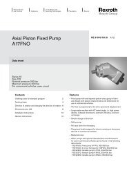
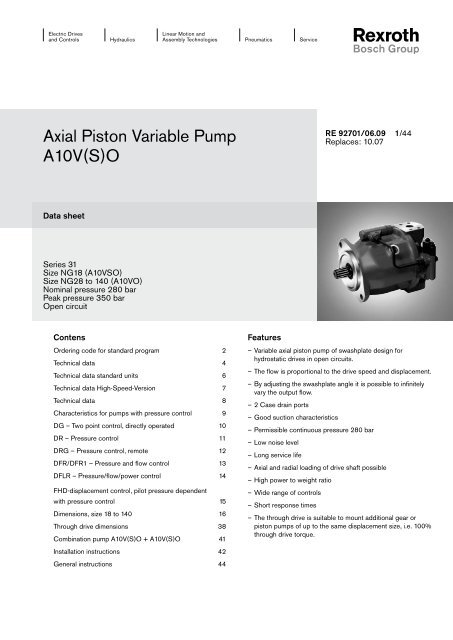
Electric Drivesand ControlsHydraulicsLinear Motion andAssembly TechnologiesPneumaticsService<strong>Axial</strong> <strong>Piston</strong> <strong>Variable</strong> <strong>Pump</strong><strong>A10V</strong>(S)ORE 92701/06.09 1/44Replaces: 10.07Data sheetSeries 31Size NG18 (<strong>A10V</strong>SO)Size NG28 to 140 (<strong>A10V</strong>O)Nominal pressure 280 barPeak pressure 350 barOpen circuitContensOrdering code for standard program 2Technical data 4Technical data standard units 6Technical data High-Speed-Version 7Technical data 8Characteristics for pumps with pressure control 9DG – Two point control, directly operated 10DR – Pressure control 11DRG – Pressure control, remote 12DFR/DFR1 – Pressure and flow control 13DFLR – Pressure/flow/power control 14FHD-displacement control, pilot pressure dependentwith pressure control 15Dimensions, size 18 to 140 16Through drive dimensions 38Combination pump <strong>A10V</strong>(S)O + <strong>A10V</strong>(S)O 41Installation instructions 42General instructions 44Features––<strong>Variable</strong> axial piston pump of swashplate design forhydrostatic drives in open circuits.––The flow is proportional to the drive speed and displacement.––By adjusting the swashplate angle it is possible to infinitelyvary the output flow.––2 Case drain ports––Good suction characteristics––Permissible continuous pressure 280 bar––Low noise level––Long service life––<strong>Axial</strong> and radial loading of drive shaft possible––High power to weight ratio––Wide range of controls––Short response times––The through drive is suitable to mount additional gear orpiston pumps of up to the same displacement size, i.e. 100%through drive torque.
2/44 Bosch Rexroth AG <strong>A10V</strong>(S)O Series 31 RE 92701/06.09Ordering code for standard program<strong>A10V</strong>(S) O / 31 – V01 02 03 04 05 06 07 08 09 10 11 12Version 18 28 45 71 100 14001 High-Speed-Version – – H02<strong>Axial</strong> piston unit 18 28 45 71 100 140Swashplate design, variable – <strong>A10V</strong>Operation mode – – – – – <strong>A10V</strong>S03 <strong>Pump</strong>, open circuit OSize04 Displacement V g max in cm 3 18 28 45 71 100 14005Control device 18 28 45 71 100 140Two point control, directly operated DGPressure control DRhydraulic, remotely operated DRGX - T open DFRwith hydraulic flow control X - T closed withflushing function DFR1with flow control,differential pressure control,m – EF 1)electrically adjustableelectric with inverse prop. curve ED 2)Pressure/flow and power control – DFLRDisplacement control, pilot press. dependent with press.control – FHDSeries06 Series 3, Index 1 31Direction of rotationViewed from drive shaft clockwise R07counter-clockwiseLSeals08 FKM (Fluor-caoutchouc) VDrive shaft 18 28 45 71 100 140Splined shaft, ANSI B92.1a-1976, standard shaft SSimilar to „S“ however for higher drive torque – – R09 Splined shaft, ANSI B92.1a-1976, reduced spline size,not with through drive m USimilar to „U“, higher drive torque, not with through drive – m WMounting flange 18 28 45 71 100 140ISO 3019-1 – 2-bolt C10ISO 3019-1 – 4-bolt – – – – – D1)See also RE 927092)See also RE 92707l = Available m = On request – = Not available ▲ = Not for new applications = Preferred program
RE 92701/06.09 <strong>A10V</strong>(S)O Series 31 Bosch Rexroth AG 7/44Technical data High-Speed-VersionTable of values (without considering efficiencies and tolerances; values rounded)Size NG 45 71 100 140Displacementvariable pump V g max cm 3 45 71 100 140Speed 1)Flowmaximum at V g max n max rpm 3000 2550 2300 2050maximum at V g < V g max2)n max perm. rpm 3300 2800 2500 2200at n max and V g max q v max L/min 135 178 230 287Powerat n max Δp = 280 bar P max kW 63 83 107 134at n = 1500 rpm P kW 32 50 70 98Torqueat V g max and Δp = 280 bar T max Nm 200 316 445 623Δp = 100 bar T Nm 72 113 159 223Torsional stiffness drive shaft S c Nm/rad 37499 71884 121142 169537drive shaft R c Nm/rad 41025 76545 – –drive shaft U c Nm/rad 30077 52779 91093 –drive shaft W c Nm/rad 34463 57460 101847 –Moment of inertiarotary unitJ TW kgm 2 0.0033 0.0083 0.0167 0.0242Case volume V L 1.0 1.6 2.2 3.0Weight (without through drive) approx. m kg 21 33 45 601)Values shown are valid for an absolute pressure (p abs ) of 1 bar at inlet port S and use with mineral oil(with a specific weight of 0,88kg/L).2)Don´t exceed the maximum flow (q v max ).NoteExceeding the maximum or falling below the minimum permissible values can lead to a loss of function, a reduction in operationalservice life or total destruction of the axial piston unit. The permissible values can be determined through calculation.
8/44 Bosch Rexroth AG <strong>A10V</strong>(S)O Series 31 RE 92701/06.09Technical dataPermissible radial and axial forces on drive shaftSize NG 18 28 45 71 100 140Radial force, max.XFqX/2 X/2atX/2F q max N 350 1200 1500 1900 2300 2800<strong>Axial</strong> force max. ± FaxF ax N 700 1000 1500 2400 4000 4800Permissible input and through drive torquesSize NG 18 28 45 71 100 140Torque,T max Nm 80 125 200 316 445 623(at V g max and Dp = 280 bar 1) )Max. permissible input torque 2)for drive shaft S T E perm Nm 124 198 319 626 1104 1620SAE J744 (ANSI B92.1a-1976) in 3/4 7/8 1 1 1/4 1 1/2 1 3/4for drive shaft R T E perm Nm 160 250 400 644 – –SAE J744 (ANSI B92.1a-1976) in 3/4 7/8 1 1 1/4 – –for drive shaft U T E perm Nm 59 105 188 300 595 –SAE J744 (ANSI B92.1a-1976) in 5/8 3/4 7/8 1 1 1/4 –for drive shaft W T E perml Nm – 140 220 394 636 –SAE J744 (ANSI B92.1a-1976) in – 3/4 7/8 1 1 1/4 –Max. permissible through drivetorquefor drive shaft S T D perm Nm 108 160 319 492 778 1266for drive shaft R T Dperm Nm 120 176 365 548 – –1)Without considering efficiency2)For drive shafts without radial loadDistribution of torquesT 1 T 2T E1. <strong>Pump</strong>e2. <strong>Pump</strong>e1. <strong>Pump</strong>e 2. <strong>Pump</strong>eT D
RE 92701/06.09 <strong>A10V</strong>(S)O Series 31 Bosch Rexroth AG 9/44Characteristics for pumps with pressure controlDrive power and flow(Fluid: hydraulic fluid ISO VG 46 DIN 51519, t = 50°C)Size 18n = 1500 rpmn = 3300 rpmFlow qV [L/min]604020302010Size 100n = 1500 rpmn = 2000 rpmP qv max00140700 50 100 150 200 250 280120P qv max60Operating pressure p [bar]100508040Size 286030n = 1500 rpm40P qv Null20n = 3000 rpm2010908040000 50 100 150 200 250 28060 q v 30P qv maxOperating pressure p [bar]402020P qv Null10Size 140000 50 100 150 200 250 280n = 1500 rpmOperating pressure p [bar]n = 1800 rpmq vq vFlow qV [L/min]P qv NullDrive power P [kW]Drive power P [kW]Flow qV [L/min]2001801601009080Drive power P [kW]q vq vq vSize 45n = 1500 rpmn = 2600 rpmFlow qV [L/min]1101008060402000 50 100 150 200 250 280Size 71n = 1500 rpmn = 2200 rpmFlow qV [L/min]160140120100806040200P qv NullP qv maxOperating pressure p [bar]P qv NullP qv max0 50 100 150 200 250 280Operating pressure p [bar]605040302010080706050403020100Drive power P [kW]Drive power P [kW]Flow qV [L/min]260240220200180160140120100806040200P qv maxP qv Null0 50 100 150 200 250 280Operating pressure p [bar]1301201101009080706050403020100Drive power P [kW]
10/44 Bosch Rexroth AG <strong>A10V</strong>(S)O Series 31 RE 92701/06.09DG – Two point control, directly operatedThe pump can be set to a minimum swivel angle by connectingan external control pressure to port X.This will supply control fluid directly to the stroking piston; aminimum pressure of p st ≥ 50 bar is required.Schematic DGXThe pump can only be switched between V g max or V g min.Please note, that the required control pressure at port X isdirectly dependent on the actual operating pressure p B in portB. (see control pressure diagram).Control pressure p st in X = 0 barControl pressure p st in X ≥ 50 barV g maxV g minThe max. permissible control pressure amounts top st = 120 bar.LBControl pressure diagramL 1SReq. control press. pst [bar]120100500 50 70 140 210 280Operating pressure p B [bar]PortsB Outlet portS Inlet portL, L 1 Case drain port (L 1 plugged)X Control pressure port (plugged)
RE 92701/06.09 <strong>A10V</strong>(S)O Series 31 Bosch Rexroth AG 11/44DR – Pressure controlThe DR-pressure control limits the maximum pressure atthe pump outlet within the pump‘s control range. The pumptherefore supplies only the amount of fluid as required by theactuators. This maximum pressure level can be set steplessly atthe control valve.Static characteristic(at n 1 = 1500 rpm; t fluid = 50°C)Schematic DR size 18 to 100LBOperating pressure pB [bar]280Setting range35Hysteresis and pressure rise ∆pmaxSize 140L 1SFlow q vPortsB Outlet portS Inlet portL, L 1 Case drain port (L 1 plugged)Controller dataHysteresis and repetitive accuracy ∆p max. 3 barPressure rise, maxSize 18 28 45 71 100 140∆p bar 4 4 6 8 10 12Pilot fluid consumption max. approx. 3 L/minFlow loss at q Vmax see page 9.
RE 92701/06.09 <strong>A10V</strong>(S)O Series 31 Bosch Rexroth AG 15/44FHD-displacement control, pilot pressure dependent with pressure controlThe swivel angle of the pump and hence the displacement orflow, is dependent on the pilot pressure p St X in port X.A constant pressure p Y = 35 bar is required at port Y. An overridingpressure control is integrated and can be steplessly setat the control valve.Please indicate setting values in clear text.Controller dataSchematic FHD size 28 to 100M StYXHysteresis ± 2 % of V g maxExternal pilot fluid consumption in Y max. approx. 3 to 4,5 L/minLBPressure rise ∆p_____________________________ max. 4 barM BMinimum system pressure p min _____________________18 barFlow loss at q v max see page 9.Static characteristic(at n 1 = 1500 rpm; t fluid = 50° C)Displacement Vg/Vg max [%]10080604020Hysteresis and pressure rise ∆pSetting range18 12 6 35280Pilot pressure Operating pressure p [bar]p St X [bar]Size 140M StL 1YXSLBL 1SPortsB Outlet portS Inlet portL, L 1 Case drain port (L 1 plugged)Mst Gauging port pilot support pressure (closed)MB Gauging port operating pressure (plugged)Y Pilot support pressureX Pilot pressure port
16/44 Bosch Rexroth AG <strong>A10V</strong>(S)O Series 31 RE 92701/06.09Dimensions, size 18DFR/DFR1 Pressure /flow control with port plate 12; clockwise rotationBefore finalising your design please request acertified installation drawing Dimensions in mmPort plate 12VValve mounting for counterclockwise rotationFlange ISO 3019-182-2 (SAE A)6.310883LXB631145°45°LXØ82.55 h8636611.543L1145195S109126View V22.2BWS47.652.4Ø25646940max. 110106.4152Viewt WØ2026.2PortsDesignation Port for Standard Size 1) Peak pressure State[bar] 2)BPort plate 12Service line (standard pressure range)Fixing threadSAE J518DIN 133/4 inM10; 17 deep 3) 350 OSPort plate 12Inlet (standard pressure range)Fixing threadSAE J518DIN 131 in5 OM10; 17 deep 3)L Case drain DIN 3852 M16x1,5 2 O 4)L 1 Case drain DIN 3852 M16x1,5 2 plugged 4)X Pilot pressure DIN 3852 M14x1,5; 12 deep 350 OX Control press. for DG control DIN 3852 G 1/4 in 120 O1)For the max. tightening torques the instructions on page 44 must be observed.2)Application dependent pressure spikes can occur.. Please consider this when selecting measuring equipment or fittings3)For version with UNC fixing thread see RA 927014)Dependent on the installation position, port L or L 1 must be connectedO = Must be connected (plugged on delivery)
RE 92701/06.09 <strong>A10V</strong>(S)O Series 31 Bosch Rexroth AG 17/44Dimensions, size 18DGTwo point control, directly operated, port plate12DRPressure control, port plate 12Before finalising your design please request acertified installation drawing Dimensions in mmto mounting flange face148Valve mounting for counterclockwise rotationValve mounting for counterclockwise rotationXXmax. 11089 12973G 1/4 in25 +0.4126DRGPressure control, remote, port plate 12to mounting flange face108XValve mounting for counterclockwise rotationXmax. 11040109126For details of hydraulic connections see page 16Drive shaftsS splined shaft 3/4 in 11T 16/32 DP 1)SAE J744 - 19-4 (A-B)Ø3/4in1/4-20UNC-2B14223038R splined shaft 3/4 in 11T 16/32 DP 1)SAE J744 - 19-4 (A-B)ø3/4 in1/4-20UNC-2Busable spline lenght142138U splined shaft 5/8 in 9T 16/32 DP 1)SAE J744 - 16-4 (A)centering 2)R 3.15 x 6.7 DIN 332Ø5/8in15.823.831.81)ANSI B92.1a-1976, 30° pressure angle, flat base, flank centering, fit class 52)<strong>Axial</strong> retention of coupling half eg. via clamp coupling or clamping bolt
18/44 Bosch Rexroth AG <strong>A10V</strong>(S)O Series 31 RE 92701/06.09Dimensions, size 28DFR/DFR1 Pressure/flow control with port plate 11 and 12; clockwise rotationBefore finalising your design please request acertified installation drawing. Dimensions in mmFlange ISO 3019-1101-2 (SAE B)Port plate129.56.311890LXVBValve mounting for counterclockwise rotation801445°45°LX22.2S47.658.7Ø32Ø101.6 h880max. 11096Ø17474401440L1 164194WS83.5146164119136Port plate 119.5 906.3Lmax. 113X95View Z47.6Ø20B22.2Ø101.6 h843Ø20Z4530.2794514 40 L1170209226Ø3258.7SValve mounting for counterclockwise rotationView VView WB30.2
RE 92701/06.09 <strong>A10V</strong>(S)O Series 31 Bosch Rexroth AG 19/44Dimensions, size 28Drive shaftsS splined shaft 7/8 in 13T 16/32 DP 1)SAE J744 - 22-4 (B)1/4-20UNC-2BØ7/8 in1625.133.141R splined shaft 7/8 in 13T 16/32 DP 1)SAE J744 - 22-4 (B)usable spline lenghtø7/8 in1/4-20UNC-2BBefore finalising your design please request acertified installation drawing. Dimensions in mm162541U splined shaft 3/4 in 11T 16/32 DP 1)SAE J744 - 19-4 (A-B)Ø3/4 in1/4-20UNC-2B143038W splined shaft 3/4 in 11T 16/32 DP 1)SAE J744 - 19-4 (A-B)usable spline lenghtø3/4 in1/4-20UNC-2B1421381)ANSI B92.1a-1976, 30° pressure angle, flat base, flank centering, fit class 5PortsDesignation Port for Standard Size 2) Peakpressure[bar] 3)BPort plate 11/12SPort plate 11/12Service line (standard pressure range)Fixing threadInlet (standard pressure range)Fixing threadSAE J518DIN 13SAE J518DIN 133/4 in350 OM10; 17 deep 4)1 1/4 in5 OM10; 17 deep 4)L Case drain DIN 3852 M18x1,5; 12 deep 2 O 5)L 1 Case drain ISO 11926 3/4-16 UNF-2B 2 plugged 5)X Pilot pressure DIN 3852 M14x1,5; 12 deep 350 OX Control pressure for DG control DIN 3852 G 1/4 in 120 OY Pilot support pressure DIN 3852 M14x1,5; 12 deep max. 35 OM B Measuring outlet pressure DIN 3852 G 1/4 in 350 pluggedM st Measuring pilot support press. DIN 3853/ Tube dia.8 mm max. 18 closedISO 8434DIN 38612)For the max. tightening torques the instructions on page 44 must be observed.3)Application dependent pressure spikes can occur.. Please consider this when selecting measuring equipment or fittings4)For version with UNC fixing thread see RA 927015)Dependent on the installation position, port L or L 1 must be connectedO = Must be connected (plugged on delivery)State
20/44 Bosch Rexroth AG <strong>A10V</strong>(S)O Series 31 RE 92701/06.09Dimensions, size 28DGTwo point control directly operated, port plate11View ZValve mounting for counterclockwise rotationDGTwo point control, directly operated, port plate 12Before finalising your design please request acertified installation drawing. Dimensions in mmto mounting flange faceValve mounting for counter158clockwise rotationXL3G 1/4 in3ZG 1/4 inØ25 +0.479X25 +0.412189.5197to mounting flange face5599.512103.5DRPressure control, port plate 11DRPressure control, port plate 12max. 113ZView ZValve mounting forcounter clockwiserotationValve mounting for counterclockwise rotationXmax. 110226to mounting flange face136DRGPressure control, remote, port plate 11DRGPressure control, remote, port plate1243max. 113ZXView Z95X118to mounting flange faceValve mounting for counterclockwise rotationX40max. 110209226Valve mounting for counterclockwise rotationto mounting flange face119136
RE 92701/06.09 <strong>A10V</strong>(S)O Series 31 Bosch Rexroth AG 21/44Dimensions, size 28DFLRPressure/flow/power control, port plate 11Valve mounting for counterclockwise rotation,see page18Before finalising your design please request acertified installation drawing. Dimensions in mmDFLRPressure/flow/power control, port plate 12Valve mounting for counterclockwise rotation48X49198max. 11386X40max.110226119119135.5FHDDisplacement control, pilot pressure dependent with pressurecontrol, port plate 11Valve mounting for counterclockwise rotation,see page 182094849 95YXX8643max. 113FHDDisplacement control, pilot pressure dependent with pressurecontrol, portplate 12Valve mounting for counterclockwise rotation48 X49MB Y47134.586214226Mst55158118 169 Mst137.540 max. 110Mst119124136For details of hydraulic connections see page 18 and 19
22/44 Bosch Rexroth AG <strong>A10V</strong>(S)O Series 31 RE 92701/06.09Dimensions, size 45DFR/DFR1 Pressure/flow control, with port plate 11 and 12; clockwise rotationBefore finalising your design please request acertified installation drawing. Dimensions in mm9.56.3Flange ISO 3019-1101-2 (SAE B)Port plate 1213396LXVValve mounting for counterclockwise rotation90109Ø1445°45°LXmax. 110129146WXZ26.2BS52.469.9Ø40Ø101.6 h89080.54014.345L118421993.5146184Ø101.6 h89.56.3Port plate 1196L22840max. 110XView Z10352.4Ø25B26.250 5088Flange ISO 3019-1101-2 (SAE B)14.345L1189245SØ4069.935.7Valve mounting for counterclockwise rotationView VØ25View W35.7
RE 92701/06.09 <strong>A10V</strong>(S)O Series 31 Bosch Rexroth AG 23/44Dimensions, size 45Shaft endsS Splined shaft 1 in 15T 16/32 DP 1)SAE J744 - 25-4 (B-B)1/4-20UNC-2BØ1 in16303845.9R Splined shaft 1 in 15T 16/32 DP 1)SAE J744 - 25-4 (B-B)usable spline lenghtø1in1/4-20UNC-2BBefore finalising your design please request acertified installation drawing. Dimensions in mm1629.545.9U Splined shaft 7/8 in 13T 16/32 DP 1)SAE J744 - 22-4 (B)ø7/8in1/4-20UNC-2B1625.141W Splined shaft 7/8 in 13T 16/32 DP 1)SAE J744 - 22-4 (B)usable spline lenghtø7/8in1/4-20UNC-2B1625411)ANSI B92.1a-1976, 30° pressure angle, flat base, flank centering, fit class 5PortsDesignation Port for Standard Size 2) Peakpressure[bar] 3)BPort plate 11/12SPort plate 11/12Service line (standard pressure range)Fixing threadInlet (standard pressure range)Fixing threadSAE J518DIN 13SAE J518DIN 131 in350 OM10; 17 deep 4)1 1/2 in5 OM12; 20 deep 4)L Case drain DIN 3852 M22x1,5; 14 deep 2 O 5)L 1 Case drain ISO 11926 7/8-14 UNF-2B 2 plugged 5)X Pilot pressure DIN 3852 M14x1,5; 12 deep 350 OX Control pressure for DG control DIN 3852 G 1/4 in 120 OY Pilot support pressure DIN 3852 M14x1,5; 12 deep max. 35 OM B Measuring operating pressure DIN 3852 G 1/4 in 350 pluggedM st Measuring support pressure DIN 3853/ Tube dia. 8 mm max. 18 closedISO 8434DIN 38612)For the max. tightening torques the instructions on page 44 must be observed.3)Application dependent pressure spikes can occur.. Please consider this when selecting measuring equipment or fittings4)For version with UNC fixing thread see RA 927015)Dependent on the installation position, port L or L 1 must be connectedO = Must be connected (plugged on delivery)State
24/44 Bosch Rexroth AG <strong>A10V</strong>(S)O Series 31 RE 92701/06.09Dimensions, size 45DGTwo point control, directly operated, port plate 11Before finalising your design please request acertified installation drawing. Dimensions in mmDGTwo point control, directly operated, port plate 12View Zto mounting flange face173Valve mounting for counterclockwise rotationXXZ3G 1/4 in25 +0.488.512208.5216to mounting flange face63.5Valve mounting for counterclockwise rotation121101173G 1/4 in25 +0.4DRPressure control, port plate 11DRPressure control, port plate 12View ZValve mounting for counterclockwise rotationXmax. 110ZXmax. 110245to mounting flange faceValve mounting for counterclockwise rotation146DRGPressure control, remote, port plate 11DRGPressure control, remote, port plate 12to mounting flange face228X40max. 110XZ103BView Zto mounting flange face133XValve mounting for counterclockwise rotationX40max. 110245to mounting flange faceValve mounting fot counterclockwise rotation129146
RE 92701/06.09 <strong>A10V</strong>(S)O Series 31 Bosch Rexroth AG 25/44Dimensions, size 45DFLRPressure/flow/power control, port plate 11Before finalising your design please request acertified installation drawing. Dimensions in mmDFLRPressure/flow/power control, port plate 1254Valve mounting for counterclockwise rotationsee page 22X49213Valve mounting for counterclockwise rotationXmax. 11011291X40112245128129146FHDDisplacement control, pilot pressure dependent with pressurecontrol; port plate 1154228X91.5Y49103X40112FHDDisplacement control, pilot pressure dependent with pressurecontrol; port plate 12187ZValve mounting f. c. clockwise rot.XY49MBX5591.540 112233245Mst63.5Valve mounting forcounter clockwiserotation see page 22137174View Z34B30 MBMst129134146137For details of hydraulic connections see page 22 and 23.
26/44 Bosch Rexroth AG <strong>A10V</strong>(S)O Series 31 RE 92701/06.09Dimensions, size 71DFR/DFR1 Pressure/flow control, with port plate 41 and 42; clockwise rotation12.7 1616 115Flange ISO 3019-1127-2 (SAE C)View V52.4Ø2526.2Ø127 h8Port plate 421853L1LXL217257Valve mounting for counterclockwise rotationV104104124Ø18107.5Before finalising your design please request acertified installation drawing. Dimensions in mm45°18121045°143160X4092 max. 110View WBPort plate 4112.76 115262LWView Z11326.2B Ø2577.8Ø5042.9SØ127 h8LX40max. 110XZSB42.9 52.458 581853L1223279SØ5077.8Valve mounting forcounter clockwise rotationPortsDesignation Port for Standard Size 1) Peakpressure[bar] 2)BPort plate 41/42BPort plate 11/12SPort plate 41/42Port plate 11/12Service line (standard pressure range)Fixing threadService line (standard pressure range)Fixing threadInlet (standard pressure range)Fixing threadFixing threadSAE J518DIN 13SAE J518DIN 13SAE J518DIN 13DIN 131 in350 OM10; 17 deep 3)1 in (+ 1 1/4 in) 350 (250) OM10; 17 deep 3)2 in5 OM12; 20 deep 3)M12; 20 deep 3)L Case drain DIN 3852 M22x1,5; 14 deep 2 O 4)L 1 Case drain ISO 11926 7/8-14 UNF-2B 2 plugged 4)X Pilot pressure DIN 3852 M14x1,5; 12 deep 350 OX Control pressure for DG control DIN 3852 G 1/4 in 120 OY Pilot support pressure DIN 3852 M14x1,5; 12 deep max. 35 OM B Measuring operating pressure DIN 3852 G 1/4 in 350 pluggedM st Measuring support pressure DIN 3853/ Tube dia. 8 mm max. 18 closedISO 8434DIN 38611)For the max. tightening torques the instructions on page 44 must be observed.2)Application dependent pressure spikes can occur.. Please consider this when selecting measuring equipment or fittings3)For version with UNC fixing thread see RA 927014)Dependent on the installation position, port L or L 1 must be connectedO = Must be connected (plugged on delivery)State
RE 92701/06.09 <strong>A10V</strong>(S)O Series 31 Bosch Rexroth AG 27/44Dimensions, size 71Before finalising your design please requesr acertified installation drawing. Dimensions in mmDFR/DFR1 Pressure/flow control, with port plate 11 and 12 not for new applications; cw rotationPort plate 12LXL217257V10410458.7(SAE 1 1/4in)77.8Ø50View V52.4B Ø2530.2View W26.2SSAE 1inNoteAt pressure port „B“ there are two SAE flanged portsavailable, each offset by 90°.SAE 1 1/4 inch, standard pressure range, 3000 psi forpressures up to 250 bar orSAE 1 inch, standard pressure range, 5000 psi, forpressures up to 350 barFor operating pressures above 250 bar the SAE 1inch port must be usedFor thread of mounting bolts see table on page 26.Port plate 11WB42.926.2Ø25SAE 1in(SAE 1 1/4in)58.730.2LXB52.4Z58S42.958Drive shafts223279For details of hydraulic connections see page 26S Splined shaft 1 1/4 in 14T 12/24 DP 1)SAE J744 - 32-4 (C)5/16-18UNC-2BØ1 1/4in1939.547.555.4SØ5077.8R Splined shaft 1 1/4 in 14T 12/24 DP 1)SAE J744 - 32-4 (C)usable spline lenghtø1 1/4in5/16-18UNC-2B193855.4U Splined shaft 1 in 15T 16/32 DP 1)SAE J744 - 25-4 (B-B)ø1 in1/4-20UNC-2B16303845.9W Splined shaft 1 in 15T 16/32 DP 1)SAE J744 - 25-4 (B-B)usable spline lenghtø1 in1/4-20UNC-2B163045.91)ANSI B92.1a-1976, 30° pressure angle, flat base, flank centering, fit class 5
28/44 Bosch Rexroth AG <strong>A10V</strong>(S)O Series 31 RE 92701/06.09Dimensions , size 71DGTwo point control, directly operated, port plate 41Before finalising your design please request acertified installation drawing. Dimensions in mmDGTwo point control, directly operated, port plate 42View Zto mounting flange face201Valve mounting for counterclockwise rotationLXZBL3G 1/4inX25 +0.412242.52503G 1/4 in25 +0.4to mounting flange faceS73.5Valve mounting for counterclockwise rotation12123.5127.5DRPressure control port plate 41DRPressure control, port plate 42View ZValve mounting for counterclockwise rotationLXmax. 110ZBLX110maxS279to mounting flange faceValve mounting for counterclockwise rotation160DRGPressure control, remote, port plate 41DRGPressure control, remote, port plate 42113View Zto mounting flange face161XValve mounting for counterclockwise rotationLX40max. 110XZBLX11040maxS262279to mounting flange faceValve mounting for counterclockwise rotation143160
XRE 92701/06.09 <strong>A10V</strong>(S)O Series 31 Bosch Rexroth AG 29/44Dimensions, size 71DFLRPressure/flow/power control, port plate41Before finalising your design please request acertified installation drawing. Dimensions in mmDFLRPressure/flow/power control, port plate 4269242Lmax. 110103X 49 L124X40124279138Valve mounting for counterclockwise rotation see page 26Valve mounting for counterclockwise rotation143159.5FHDDisplacement control, pilot pressure dependent with pressurecontrol; port plate 41FHDDisplacement control, pilot pressure dependent with pressurecontrol; port plate 42115262LX40max. 110103.5Y49113137.5 124X218161 MBXL3069103.549Y40137.5 124267279Mst73.5118201Mst14 314 816 0MstValve mounting for counterclockwise rotation see page 26Valve mounting for counterclockwise rotationFor details of hydraulic connections see page 26.
30/44 Bosch Rexroth AG <strong>A10V</strong>(S)O Series 31 RE 92701/06.09Dimensions, size 100DFR/DFR1 Pressure/flow control, with port plate 11 and 12; clockwise rotationPort plate 12Before finalising your design please request acertified installation drawing. Dimensions in mmFlange ISO 3019-1127-2 (SAE C)Ø127h812.76229175XV10010017.515213645°X40max. 110952095L1275317WB118Valve mounting for counterclockwise rotationView V181210148.4164.9View WØ3266.788.9Ø6031.850.8SPort plate 11View ZFlange ISO 3019-1127-2 (SAE C)Ø127h812.76175LX40max. 110ZX12166.7Ø32B31.85550.8552095L1288327344Ø6088.9SValve mounting for counterclockwise rotation
RE 92701/06.09 <strong>A10V</strong>(S)O Series 31 Bosch Rexroth AG 31/44Dimensions, size 100Drive shaftsBefore finalising your design please request acertified installation drawing. Dimensions in mmS Splined shaft 1 1/2 in 17T 12/24 DP 1)SAE J744 - 38-4 (C-C)7/16-14UNC-2BØ1 1/2in2843.65461.9U Splined shaft 1 1/4 in 14T 12/24 DP 1)SAE J744 - 32-4 (C)ø1 1/4in5/16-18UNC-2B193555.4W Splined shaft 1 1/4 in 14T 12/24 DP 1)SAE J744 - 32-4 (C)usable spline lenghtø1 1/4in5/16-18UNC-2B193555.41)ANSI B92.1a-1976, 30° pressure angle, flat base, flank centering, fit class 5PortsDesignation Port for Standard Size 2) Peakpressure[bar] 3)BPort plate 11/12SPort plate 11/12Service line (high pressure range)Fixing threadInlet (standard pressure range)Fixing threadSAE J518DIN 13SAE J518DIN 131 1/4 in350 OM14; 19 deep 4)2 1/2 in5 OM12; 17 deep 4)L Case drain DIN 3852 M27x2; 16 deep 2 O 5)L 1 Case drain ISO 11926 1 1/16-12 UNF-2B 2 plugged 5)X Pilot pressure DIN 3852 M14x1,5; 12 deep 350 OX Control pressure for DG control DIN 3852 G 1/4 in 120 OY Pilot support pressure DIN 3852 M14x1,5; 12 deep max. 35 OM B Measuring operating pressure DIN 3852 G 1/4 in 350 pluggedM st Measuring pilot support pressure DIN 3853/ Tube dia. 8 mm max. 18 closedISO 8434DIN 38612)For the max. tightening torques the instructions on page 44 must be observed.3)Application dependent pressure spikes can occur.. Please consider this when selecting measuring equipment or fittings4)For version with UNC fixing thread see RA 927015)Dependent on the installation position, port L or L 1 must be connectedO = Must be connected (plugged on delivery)State
32/44 Bosch Rexroth AG <strong>A10V</strong>(S)O Series 31 RE 92701/06.09Dimensions, size 100DGTwo point control, directly operated, port plate 11View ZDGTwo point control, directly operated, port plate 12to mounting flange faceBefore finalising your design please request acertified installation drawing. Dimensions in mm268123083G 1/4 in25 +0.4315Xto mounting flange faceZ81Valve mounting for counterclockwise rotationValve mounting for counterclockwise rotation12128.5132.5X3R 1/4in25 +0.4DRPressure control, port plate 11DRPressure control, port plate 12to mounting flange face344View ZXmax. 110ZXmax. 110Valve mounting for counterclockwise rotationValve mounting for counterclockwise rotation165DRGPressure control, remote, port plate 11DRGPressure control, remote, port plate 12to mounting flange face327344X40max. 110XZ121View Zto mounting flange face228XX40max. 110Valve mounting for counterclockwise rotationValve mounting for counterclockwise rotation148165
XRE 92701/06.09 <strong>A10V</strong>(S)O Series 31 Bosch Rexroth AG 33/44Dimensions, size 100DFLRPressure/flow/power control, port plate 11Before finalising your design please request acertified installation drawing Dimensions in mmDFLRPressure/flow/power control, port plate 12111 X49308X148108.5129129XValve mounting for counterclockwise rotation344max. 110145.340164.5Valve mounting forcounter clockwiserotation see page 30FHDDisplacement control, pilot pressure dependent with pressurecontrol; port plate 11111XView Z12149YFHDDisplacement control, pilot pressure dependent with pressurecontrol; port plate 12275228XM B4932733234440max. 110M STZ80131129108.5129Valve mounting for counterclockwise rotation26827586M ST108.5148153165Valve mounting for counterclockwise rotation40129129For details of hydraulic connections see page 30 and 31.
34/44 Bosch Rexroth AG <strong>A10V</strong>(S)O Series 31 RE 92701/06.09Dimensions, size 140Before finalising your design please request acertified installation drawing. Dimensions in mmDFR/DFR1 Pressure/flow control, with port plate 11 and 12, mounting flange D; cw rotation88.9Ø6350.8View WView V31.8Ø32SBName plate66.712.76.4Flange ISO 3019-1152-4 (SAE D)Ø152.4 h82178244173LPort plate1112.76.4 173Flange ISO 3019-1152-4 (SAE D)View YØ152.4 h8Port plate 122178L1275317L1YLLX293353379VWValve mounting for counterclockwise rotation20.6110110200161.612526Z131X45°148.5BL161.6200183209View Z11866.7Ø32Ø6388.9SBS2612610811250.8 31.860 60Valve mounting for counterclockwise rotationPortsDesignation Port for Standard Size 1) Peakpressure[bar] 2)BPort plate 11/12SPort plate 11/12Service line (high pressure range)Fixing threadInlet (standard pressure range)Fixing threadSAE J518DIN 13SAE J518DIN 131 1/4 in350 OM14; 19 deep 3)2 1/2 in5 OM12; 17 deep 3)L Case drain DIN 3852 M27x2; 16 deep 2 O 4)L 1 Case drain ISO 11926 1 1/16-12 UNF-2B 2 plugged 4)X Pilot pressure DIN 3852 M14x1,5; 12 deep 350 OX Control pressure for DG control DIN 3852 M14x1,5; 12 deep 120 OY Support pilot pressure DIN 3852 M14x1,5; 12 deep max. 35 OM st Measuring support pilot pressure DIN 3853/ Tube dia. 8 mm max. 18 closedISO 8434DIN 3861M H Measuring operating pressure DIN 3852 M14x1,5; 12 deep 350 plugged1)For the max. tightening torques the instructions on page 44 must be observed.2)Application dependent pressure spikes can occur.. Please consider this when selecting measuring equipment or fittings3)For version with UNC fixing thread see RA 927014)Dependent on the installation position, port L or L 1 must be connectedO = Must be connected (plugged on delivery)State
RE 92701/06.09 <strong>A10V</strong>(S)O Series 31 Bosch Rexroth AG 35/44Dimensions, size 140Before finalising your design please request acertified installation drawing. Dimensions in mmDFR/DFR1 Pressure/flow control, with port plate 11 and 12, mounting flange C, cw rotationPort plate 1288.9Ø63View W50.8S12.76Flange ISO 3019-1127-2 (SAE C)Ø127 h8270.5199LXVB11011015217.545°118.526126108112View V31.8Ø3266.7Port plate 11B12.76Flange ISO 3019-1127-2 (SAE C)Ø127 h82010420104L1301343379199LL1319405WSX12526ZX131Valve mounting forcounter clockwiserotation181210118View ZB66.7Ø32Ø6388.9183209SBS50.8 31.860 60Valve mounting for counterclockwise rotationFor details of hydraulic connections see page 34.Drive shaftS Splined shaft 1 3/4 in 13T 8/16 DP 1)SAE J744 - 44-4 (D)1/2-13UNC-2BØ1 3/4in325367751)ANSI B92.1a-1976, 30° pressure angle, flat base, flank centering, fit class 5
36/44 Bosch Rexroth AG <strong>A10V</strong>(S)O Series 31 RE 92701/06.09Dimensions, size 140DGTwo point control, directly operated, port plate 11; D-flangeBefore finalising your design please request acertified installation drawing. Dimensions in mmDGTwo point control, directly operated, port plate 12; D-flangeView Z268to mounting flange faceLXM14x1.52.6ZBLX2.612322327M14x1.5MH2894Valve mounting for counterclockwise rotationSValve mounting for counterclockwise rotation1215315828108112MHto mounting flange faceDRPressure control, port plate 11; D-flangeDRPressure control, port plate 12; D-flangeView ZL126BL26126ZS339170to mounting flange faceValve mounting for counterclockwise rotationValve mounting for counterclockwise rotationDRGPressure control, remote, port plate 11; D-flangeDRGPressure control, remote, port plate 12; D-flangeL26126XView Z118BL292to mounting flange faceX126Z56S313339to mounting flange faceValve mounting for counterclockwise rotationValve mounting for counterclockwise rotation144170
RE 92701/06.09 <strong>A10V</strong>(S)O Series 31 Bosch Rexroth AG 37/44Dimensions, size 140DFLRPressure/flow/power control, port plate 11; D-flangeBefore finalising your design please request acertified installation drawing. Dimensions in mmDFLRPressure/flow/power control, port plate 12; D-flangeValve mounting forcounter clockwiserotation see page 3499 49X314L119126139.5LX56108139.537916318 3209Valve mounting for counterclockwise rotationFHDDisplacement control, pilot pressure dependent with pressurecontrol; port plate 11; D-flangeFHDDisplacement control, pilot pressure dependent with pressurecontrol; port plate 12; D-flangeView Z99353 118X49Y99244XY49L26ZB119139.5L11926150 139S353379Mst148 94Valve mounting for counterclockwise rotation268Valve mounting for counterclockwise rotation184210MstFor details of hydraulic connections see page 34 and 35.
38/44 Bosch Rexroth AG <strong>A10V</strong>(S)O Series 31 RE 92701/06.09Through drive dimensionsK01 Flange ISO 3019-1 - 82-2 (A)Coupler for splined shaft to ANSI B92.1a-1976 5/8in 9T 16/32 DP 1)(SAE J744 - 16-4 (A))Before finalising your design please request acertified installation drawing. Dimensions in mmA45°A 4A 19Size A 1 A 4 A 518 182 43 M10; 14,5 deep28 204 47 M10; 16 deep45 229 53 M10; 16 deepø106.5ø82.55 +0.050+0.02071 267 61 M10; 20 deep100 338 65 M10; 20 deep140 2) 350 77 M10; 17 deep2)D-flange onlyBA 5to mounting flange face10K52 Flange ISO 3019-1 - 82-2 (A)Coupler for splined shaft to ANSI B92.1a-1976 3/4in 11T 16/32 DP 1) (SAE J744 - 19-4 (A-B))45°A 3Size A 1 A 2 A 3 A 4 A 518 182 39 17,5 43 M10; 14,5 deep28 204 39 17,5 47 M10; 16 deep45 229 39 17,5 53 M10; 16 deepA A 410ø106.5ø82.55 +0.050+0.02071 267 39 17,5 61 M10; 20 deep100 338 39 17,5 65 M10; 20 deep140 2) 350 39 17,5 77 M10; 17 deep2)D-flange onlyBA 5A 2to mounting flange face A 1K68 Flange ISO 3019-1 - 101-2 (B)Coupler for splined shaft to ANSI B92.1a-1976 7/8in 13T 16/32 DP 1) (SAE J744 - 22-4 (B))omitted onsize28A45°A 3Size A 1 A 2 A 3 A 4 A 528 204 42 16,5 47 M12;through bore45 229 42 16,5 53 M12; 18 deepø146A 5A 410ø101. 6 +0.050+0.02071 267 42 16,5 61 M12; 20 deep100 338 42 16,5 65 M12; 20 deep140 2) 350 42 16,5 77 M12; 20 deep2)D-flange onlyomitted on size 28Bto mounting flange faceA 2A 11)30° pressure angle, flat base, flank centering, fit classe 5
RE 92701/06.09 <strong>A10V</strong>(S)O Series 31 Bosch Rexroth AG 39/44Through drive dimensionsK04 Flange ISO 3019-1 - 101-2 (B)Coupler for splined shaft to ANSI B92.1a-1976 1in 15T 16/32 DP 1)(SAE J744 - 25-4 (B-B))Before finalising your design please request acertified installation drawing Dimensions in mmA45°Size A 1 A 3 A 4 A 545 229 18 47 M12; 18 deep71 267 18 47 M12; 20 deep100 338 18 47 M12; 20 deepø146A 5A 310ø101.6 +0.050+0.020140 2) 350 18 47 M12; 20 deep2)D-flange onlyBA 4to mounting flange face A 1K07 Flange ISO 3019-1 - 127-2 (C)Coupler for splined shaft to ANSI B92.1a-1976 1 1/4in 14T 12/24 DP 1) (SAE J744 - 32-4 (C))Size A 1 A 2 A 3 A 4 A 5Aomitted on size 7145°ø181omitted on size 71A 3ø127 +0.050+0.020BA 4A 2A 171 267 56,5 17,9 61 M16;through bore100 338 56,5 17,9 65 M16;through bore140 2) 350 56,5 17,9 77 M16; 24 deep2)D-flange onlyto mounting flange face13K24 Flange ISO 3019-1 - 127-2 (C)Coupler for splined shaft to ANSI B92.1a-1976 1 1/2in 17T 12/24 DP 1) (SAE J744 - 38-4 (C-C))A45°Size A 1 A 3 A 4 A 5100 338 8 65 M16;through bore140 2) 350 8 77 M16; 24 deepø181A 4A 3A 113ø127 +0.050+0.0202)D-flange onlyA 5Bto mounting flange face1)30° pressure angle, flat base, flank centering, fit class 5
40/44 Bosch Rexroth AG <strong>A10V</strong>(S)O Series 31 RE 92701/06.09Through drive dimensionsBefore finalising your design please request acertified installation drawing. Dimensions in mmK17 Flange ISO 3019-1 - 152-4 (D)Coupler for splined shaft to ANSI B92.1a-1976 1 3/4in 13T 8/16 DP 1) (SAE J744 - 44-4 (D))161.6A 4AA 3B A 5to mounting flange face A 1161.6ø152.4 +0.07+0.0213Size A 1 A 3 A 4 A 5140 2) 350 8 77 M16;through bore2)D-flange only1)30° pressure angle, flat base, flank centering, fit class 5
RE 92701/06.09 <strong>A10V</strong>(S)O Series 31 Bosch Rexroth AG 41/44Combination pump <strong>A10V</strong>(S)O + <strong>A10V</strong>(S)OThe use of combination pumps offers the possibility of independentpump circuits without the need for a splitter gearbox.When ordering combination pumps the designations for the 1 stand the 2 nd pump must be joined by a „+“ sign.Example:<strong>A10V</strong>O 100DR/31R-VSC12K07 +<strong>A10V</strong>O 71DR/31R-VSC12N00If a gear pump or a radial piston pump must be factory-mountedplease consult us.Permissible moment of inertiaThe <strong>A10V</strong>(S)O axial piston unit can be supplied with a throughdrive according to the ordering code on page 3. The throughdrive version is designated by the code numbers (K01-K24). Ifno other pumps are factory-mounted, the simple type designationis sufficient.The delivery of a pump with through drive includes the shaftcoupler, the seal and if applicable an adapter flange.Every through drive is closed with a non protective coverupon delivery. Prior to start up this cover must be replaced by apressure tight cover (or a 2nd pump).Through drives can be ordered with a pressure tight cover.Please indicate in clear text.It is permissible to combine two single pumps of the same size (tandem pump) and operate the combination with a max. permissibledynamic acceleration of 10g (98.1 m/s 2 ) without additional support.Size 18 28 45 71 100 140Permissible moment of inertiastatic T m Nm 500 880 1370 2160 3000 4500 1)dynamic at 10g (98.1 m/s 2 ) T m Nm 50 88 137 216 300 450 1)Weight m kg 12 15 21 33 45 60To center of gravity L 1 mm 90 110 130 150 160 1601)4-bolt flange (D)2)2-bolt flange (C) Combination pumps max. permissible as double pump of the same size.3000 2)300 2)m 1 , m 2 , m 3 Weight of pumps [kg]m 1 m 2 m 3l 1 , l 2 , l 3 Distance to center of [mm]gravity1Tm = (m 1 • l 1 + m 2 • l 2 + m 3 • l 3 ) • [Nm]102l 1l 2l 3Overview of through drive mounting optionsThrough drive - <strong>A10V</strong>(S)O Mounting option - 2. pump ThroughFlangeCoupler for splined Code <strong>A10V</strong>(S)O/31 <strong>A10V</strong>(S)O/52 (53) Gear pumpdrive availableon(SAE-J744) shaftSize (shaft) Size (shaft)size82-2 (A) 16-4 (5/8 in) K01 18 (U) 10 (U) (18 (U)) Series F 18 to 14019-4 (3/4 in) K52 18 (S, R) 10 (S) (18 (S, R)) 18 to 140101-2 (B) 22-4 (7/8 in) K68 28 (S, R) 28 (S, R) Series N, G 28 to 14045 (U, W) 1) 45 (U, W) 1)25-4 (1 in) K04 45 (S, R) 45 (S, R) 45 to 10063 (U, W) 2)127-2 (C) 32-4 (1 1/4 in) K07 71 (S, R) 85 (U, W) 3) 71 to 140100 (U) 3)38-4 (1 1/2 in) K24 100 (S) 85 (S) 100 to 140152-4 (4-bolt) 44-4 (1 3/4 in) K17 140 (S) 1401)Not with K68-through drive on main pump size 282)Not with K04-through drive on main pump size 453)Not with K07-through drive on main pump size 71
42/44 Bosch Rexroth AG <strong>A10V</strong>(S)O Series 31 RE 92701/06.09Installation instructionsGeneralThe pump housing must be filled with fluid during commissioning and operation and must be deaerated. This must also be thecase after prolonged periods of standstill since the system can empty itself through the hydraulic lines.This is especially important with the mounting position „shaft end upwards or downwards“: make sure that the housing is completelyfilled with fluid, to prevent the bearings and shaft seal from running dry and overheating.Connect the highest one of the case drain ports with tubing of the light series wall thickness and the largest size corresponding tothe port size. In order to attain the lowest noise level, all connections (suction, pressure, pilot, and case drain) must be linked byflexible members to tank and try to avoid mounting above the reservoir.In case of combination pumps with different case drain pressures it is necessary that each pump has its own case drain line.In every operating condition the inlet and the case drain lines must always enter the reservoir below the minimum fluid level(h t min = 200 mm). The permissible suction height h depends on the overall suction pressure losses, but may never exceedh S max = 800 mm. The minimum inlet pressure at port S may not fall below the minimum value of p abs min = 0.8 bar under any staticor dynamic condition.Installation positionSee the following examples1 to 15 Recommended positions: 1 and 3.Other installation positions may be possible; please consult us..Mounting below the reservoir (Standard)This is the case whenever the pump is mounted below the min. fluid level. The pump can be installed next to or underneath thereservoir.1FLL 1min. 200 mmh t min200 mmh min100 mmSSBPosition Air bleed Filling1, 3 and 5 F S + L, L 1 (F)2 and 4 F S + L, L 1 (F)Mounting above the reservoirInstallation above the reservoir means that the pump is mounted above the min. fluid level.The use of a check valve in the casedrain line is only permissible in individual cases and only after consulting us.6 7FLL 1h s max800 mmh t min 200 mmh min 100 mmmin. 200 mmSSBPosition Air bleed Fillingmin. 200 mmFh t min200 mm SBh min100 mm6, 8 and 10 F L, L 1 (F)7 and 9 F S + L, L 1 (F)2L L 1Sh s max800 mmh t min 200 mmh min 100 mmFSB3 45min. 200 mmmin. 200 mmmin. 200 mmFFFh t minh t minh t min200 mm SB200 mm SB200 mm SBh minh minh min100 mm100 mm100 mmL 1L L 1 L 1SSLmin. 200 mmSL8 9Fh s max800 mmmin. 200 mmFLLh s max800 mmh t minh t min 200 mm SB h t min 200 mm SB 200 mmh min 100 mm h min 100 mm h min 100 mmSL 1min. 200 mmSL 110h s max800 mmLFLXL 1L 1min. 200 mmL/L 1 = Case drain port, F = air bleed- or filling port, S = inlet port, SB = baffle plate, h t min = minimum permissible immersiondepth, h S max = maximum permissible suction heightXSSSB
RE 92701/06.09 <strong>A10V</strong>(S)O Series 31 Bosch Rexroth AG 43/44Installation instructionsMounting inside the reservoir.This means that the pump is mounted within the minimum fluid level11min. 200 mm12min. 200 mm 13 min. 200 mm 14 min. 200 mm 15 min. 200 mmLL 1SBSht minh min100 mmLL 1SSBht minh min100 mmL 1 SLSBht minh min100 mmLL 1SSBht minh min100 mmLL 1XSBSht minh min100 mmPosition Air bleed Filling11, 13 and 15 L, L 1 L, L 112 and 14 L, L 1 S + L, L 1L/L 1 = Case drain port, F = air bleed- or filling port, S = inlet port, SB = baffle plate, h t min = minimum permissible immersiondepth, h S max = maximum permissible suction height
44/44 Bosch Rexroth AG <strong>A10V</strong>(S)O Series 31 RE 92701/06.09General instructions––The pump <strong>A10V</strong>(S)O was designed for operation in open loop circuits––Systems design, installation and commissioning requires trained technicians or tradesmen.––All hydraulic ports can only be used for the fastening of hydraulic service lines.––During and shortly after operation of a pump the housing and especially a solenoid can be extremely hot, avoid being burned;take suitable safety measures (wear protective clothing).––Dependent on the operating conditions of the axial piston pump (operating pressure, fluid temperature) deviations in the performancecurves can occur.––Pressure ports:All materials and port threads are selected and designed in such a manner, that they can withstand the peak pressures.The machine and system manufacturer must ensure, that all connecting elements and hydraulic lines are suitable for the actualoperating pressures.––Pressure cut off and pressure control are not suitable for providing system protection against excessive pressures. A suitableoverall main line relief valve must be incorporated.––All given data and information must be adhered to.––The following tightening torques are valid:- Female threads in the axial piston unit:the maximum permissible tightening torques M GMax are maximum values for the female threads in the pump casting and maynot be exceeded.- Fittings:please comply with the manufacturer‘s information regarding the max. permissible tightening torques for the used fittings.- Fastening bolts:for fastening bolts to DIN 13 we recommend to check the permissible tightening torques in each individual case to VDI 2230.- Plugs:for the metal plugs, supplied with the axial piston unit the following min. required tightening torques M V apply (see table)Port thread sizeMax. perm. tighteningtorque in female threadsM G maxRequired tightening torque ofplugs or fittings M VG 1/4 in ISO 11926 70 Nm7/8-14 UNF-2B ISO 11926 40 Nm 15 Nm 3/16 in1 1/16-12 UNF-2B ISO 11926 360 Nm 147 Nm 9/16 inM14x1,5 DIN 3852 80 Nm 35 Nm 6 mmM16x1,5 DIN 3852 100 Nm 50 Nm 8 mmM18x1,5 DIN 3852 140 Nm 60 Nm 8 mmM22x1,5 DIN 3852 210 Nm 80 Nm 10 mmM27x2 DIN 3852 330 Nm 135 Nm 12 mmAcross the flats in AllanscrewsBosch Rexroth AGHydraulics<strong>Axial</strong> <strong>Piston</strong> UnitsAn den Kelterwiesen 1472160 Horb, GermanyTelefon +49 (0) 74 51 92-0Telefax +49 (0) 74 51 82 21info.brm-ak@boschrexroth.dewww.boschrexroth.com/axial piston units© This document, as well as the data, specifications and other information setforth in it, are the exclusive property of Bosch Rexroth AG. It may not be reproducedor given to third parties without its consent.The data specified above only serve to describe the product. No statementsconcerning a certain condition or suitability for a certain application can be derivedfrom our information. The information given does not release the user fromthe obligation of own judgment and verification. It must be remembered that ourproducts are subject to a natural process of wear and aging.Subject to change.