Efficient Algorithm for Detecting Layered Space-Time Codes
Efficient Algorithm for Detecting Layered Space-Time Codes
Efficient Algorithm for Detecting Layered Space-Time Codes

Create successful ePaper yourself
Turn your PDF publications into a flip-book with our unique Google optimized e-Paper software.
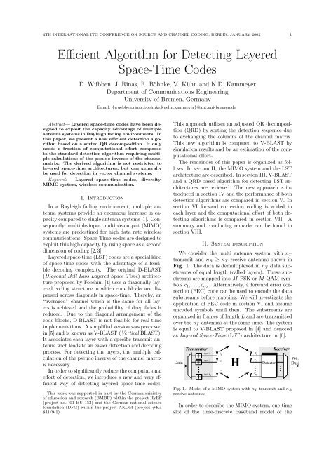
4TH INTERNATIONAL ITG CONFERENCE ON SOURCE AND CHANNEL CODING, BERLIN, JANUARY 2002 2MIMO system is investigated.Let c = (c 1 c 2 . . . c nT ) T denote the vector of transmittedsymbols, then the corresponding receivedsignal vector x = (x 1 x 2 . . . x nR ) T is calculated byx = H · c + ν . (1)In equation (1), ν = (ν 1 ν 2 . . . ν nR ) T depicts thevector of noise terms at the n R receiving antennas,assuming uncorrelated white gaussian noise ofvariance N 0 /2 per dimension <strong>for</strong> all antennas. Thetransmitted symbols are normalized so that the averagereceived energy per bit is one. The n R ×n Tchannel matrix⎛⎞h 1,1 . . . h 1,nT⎜H =⎝.. ... ..⎟⎠ (2)h nR,1 . . . h nR,n Tcontains i.i.d. complex fading gains h j,i describingthe tap gains between transmit antenna i and receiveantenna j. Column i of H is denoted by h i andrepresents the single-input multiple-output (SIMO)channel between transmit antenna i and the n R receiveantennas. We assume a static flat-fading environment,i.e. the channel matrix H is constant overa frame and changes independently from frame toframe. The distinct fading gains are assumed tobe uncorrelated and are perfectly known by the receiver.III. <strong>Detecting</strong> <strong>Layered</strong> <strong>Space</strong>-<strong>Time</strong> <strong>Codes</strong>In this paragraph, two different detection algorithms<strong>for</strong> the LST architecture are described. First,the standard detection algorithm proposed by Bell-Labs [5] and known as V-BLAST is depicted. Shiuand Kahn utilized the QR decomposition of thechannel matrix <strong>for</strong> the detection of the layers to deriveerror bounds <strong>for</strong> V-BLAST and D-BLAST in[6]. They presumed the knowledge of the best detectionsequence, but did not discuss the problemof an efficient assorting algorithm, which is done insection IV of this paper.A. BLAST-<strong>Algorithm</strong>It is obvious from equation (1) that the receivedsignals are a linear combination of the n T transmittedsignals. The optimum way of recovering the n Tsignals at the receiver would be maximum-likelihooddetection, which is not feasible due to the enormouscomplexity.In [4] and [5], Foschini et al. proposed a successiveinterference cancellation technique which nullsthe interferer by linearly weighting the received signalvector with a zero-<strong>for</strong>cing (ZF) nulling vector.In every detection step, all signals but one are regardedas interferer. By applying the nulling vectorto interference cancellation, the influence of thesesignals is nulled out, the target signal is detectedand subsequently subtracted from the received signalvector (Interference Cancellation).For detecting signal i, the nulling vector w i hasto be orthogonal to columns h l , l ≠ i of the channelmatrix. The condition 1{wi T 1 l = i· h l =(3)0 l ≠ iis fulfilled by the i-th row of the Moore-Penrosepseudo-inverseG := H + := ( H H H ) −1H H , (4)of the channel matrix H. With g (i) denoting row i ofG, the received signal vector x is linearly weightedwith the nulling vector wiT = g (i) and the resulty i = w T i · x = g (i) · (H · c + ν) (5)= c i + ˜ν i .is used as a decision statistic <strong>for</strong> the i-th substreamwhere ˜ν i = g (i) · ν denotes the actual noise. By applyingthe quantization operation Q[·] appropriateto the signal constellation, signal i can be estimated:ĉ i = Q[y i ] . (6)The interference caused by the detected signal ĉ i isnow subtracted from the received signal vector x ix i+1 = x i − h i · ĉ i (7)and the corresponding column in the channel matrixis set to zero. The indexed variables (H i ,G i ,x i ) denotefrom now on the specific variables in detectionstep i, beginning with the assignment (H 1 = H,G 1 = G, x 1 = x) in the first step. Using the nomenclatureintroduced in [5], H i+1 := H i i describes thenulling of column i of the channel matrix H i andcorresponds to an equivalent system with n T − itransmit and n R receive antennas. Thus, the pseudoinverse of this reduced channel matrix H i+1 is usedto calculate the nulling vector <strong>for</strong> detecting layeri + 1.The order of detecting affects the error probabilityof the algorithm [5]. The sequence S ={k 1 , k 2 , . . . , k nT } is defined as a permutation ofthe numbers 1, 2, . . . , n T to depict a specific detectionsequel. Thus the values y k1 , y k2 , . . . , y knTare filtered one by one, the transmitted signalsĉ k1 , ĉ k2 , . . . , ĉ knT are estimated and the interferenceis cancelled step by step according to equations (5)to (7). In order to derive the minimum total errorprobability, it is optimal always to choose and detectthe layer with the largest post detection signalto-noiseratio [5]:E { |c ki | 2}SNR ki =E {|n ki | 2 } ‖w ki ‖ 2 ∼ 1∥ ∥ g(k i) 2 . (8)1 The transpose and conjugate transpose (Hermitian) of xare denoted by x T and x H , respectively.
4TH INTERNATIONAL ITG CONFERENCE ON SOURCE AND CHANNEL CODING, BERLIN, JANUARY 2002 3Consequently, it is optimal to choose the row g (ki)iof G i with minimal norm and thus detect the associatedsignal c ki in detection step i. The wholedetection algorithm is shown in Fig. 2.(1) <strong>for</strong> i = 1, . . . , n T(2) G i = H + i(3) k i = arg minj∥ ∥∥g (j)i∥∥ 2(4) wk T i= g (ki)i(5) y ki = wk T i · x i(6) ĉ ki = Q[y ki ](7) x i+1 = x i − h ki · ĉ ki(8) H i+1 = H kii(9) endFig. 2. V-BLAST algorithm <strong>for</strong> detecting layered space-timesignalsB. QR decomposition of the channel matrixIn [6], Shiu and Kahn used the QR decompositionof the channel matrix H to derive bounds <strong>for</strong> theerror probability of LST codes. There<strong>for</strong>e, the n R ×n T channel matrix HH = Q · R , (9)is factorized into the unitary n R × n T matrix Qand the upper triangular n T × n T matrix R. Bydenoting the column i of H by h i and column iof Q by q i , the decomposition in equation (9) isdescribed columnwise by⎛⎞r 1,1 . . . r 1,nT⎜(h 1 . . . h nT ) = (q 1 . . . q nT )· ⎝. .. .⎟⎠ .0 r nT ,n T(10)By multiplying equation (1) from the left with theHermitian matrix of Q, a n T × 1 modified receivedsignal vectory = Q H · x = R · c + η . (11)is created from the n R × 1 received signal vector x.Since Q is unitary, the statistical properties of thenoise term η = Q H · ν remain unchanged. Elementk of vector y becomeswith the interference termy k = r k,k · c k + η k + d k (12)d k =n T∑i=k+1r k,i · c i . (13)Thus, y k depends on the weighted transmit signalr k,k · c k , the noise η k and the interference term d k .Since R is upper triangular, d k is independent ofthe upper layer signals c 1 , . . . , c k−1 and hence thelowest layer (transmit signal c nT ) is described byy nT = r nT ,n T · c nT + η nT . (14)Then, the decision statistic y nT is independent ofthe remaining transmit signals and can be used toestimate ĉ nT[ ]ynTĉ nT = Q(15)r nT ,n Tby applying the quantization operation Q[·].For detecting layer n T − 1, the interference termr nT −1,n T · ĉ nT is eliminated in the modified receivedsignaly nT −1 = r nT −1,n T −1·c nT −1+r nT −1,n T ·c nT +η nT −1 .(16)Consequently, an interference free decision statisticto estimate c nT −1 is obtained under the assumptionĉ nT = c nT . <strong>Detecting</strong> layer k = n T − 1, . . . , 1 takesplace in an equivalent way. With previous decisionsĉ k+1 , . . . , ĉ nT , the interference term ˆd k is calculatedand cancelled out in the modified received signaly k . Assuming that all previous decisions are correct( ˆd k = d k ), the valuez k = y k − ˆd k = r k,k · c k + η k (17)is free of interference and thus it can be used todetect c k with ĉ k = Q[z k /r k,k ].As already stated, the order of detection is crucial<strong>for</strong> the error probability of the LST system dueto the risk of error propagation [5]. When using theQR decomposition <strong>for</strong> detection, the sequence of detectionis achieved by permutating the elements ofc and the corresponding columns of H and therebyresults in different matrices Q and R. The optimumR maximizesSNR k = E { |c k | 2} |r k,k | 2E {|n ki | 2 }∼ |r k,k | 2 (18)in each step of the detection process (correspondsto the maximization of |r k,k | <strong>for</strong> k = n T , . . . , 1) andcan be found by per<strong>for</strong>ming O(n 2 T /2) QR decompositionsof permutations of H [7]. In order to reducethe computational ef<strong>for</strong>t of finding a detection sequence,we derive a suboptimal but less complexalgorithm <strong>for</strong> sorting in the next section.IV. Sorted QR decompositionIn this section, a new and very efficient approachthat comes close to the error per<strong>for</strong>mance of V-BLAST is introduced. It is basically an extensionof the modified Gram-Schmidt algorithm [8] by orderingthe columns of H in each orthogonalizationstep. In order to describe this new algorithm, wefirst review the modified Gram-Schmidt algorithmwithout sorting. In the subsequent the motivation<strong>for</strong> the sorted approach and the description of thesorted QR decomposition are presented.
4TH INTERNATIONAL ITG CONFERENCE ON SOURCE AND CHANNEL CODING, BERLIN, JANUARY 2002 5pseudo inverse of H. The strong impact of orderingthe QR decomposition is obvious and only asmall difference of approximately 0.5 dB related toV-BLAST <strong>for</strong> a BER of 10 −5 is visible <strong>for</strong> the SQRDalgorithm.10 010 −1PSfrag replacementsPseudo inverseUnsorted QRDSQRDV-BLASTBER10 010 −110 −210 −3∼ ( E bN 0) −1 ∼ ( E bN 0) −2Layer 4Layer 3Layer 2Layer 110 −210 −4frag replacementsBER10 −310 −410 −5∼ ( E bN ) −300 5 10 15 20 25 30E bin dBN 0Fig. 6. “Genie” detection in a system with n T = 4 andn R = 4 antennas, uncoded QPSK symbols10 −50 2 4 6 8 10 12 14 16 18 20E bin dBN 0Fig. 4. Simulation with n T = 8 and n R = 12 antennas,uncoded QPSK symbols, spectral efficiency of 16 Bit/s/HzFig. 5 shows the BER of the different detectionalgorithms <strong>for</strong> an uncoded system with n T = 4 andn R = 6 antennas. These results confirm the goodper<strong>for</strong>mance of the SQRD algorithm with the reducedcalculation complexity in mind.10 010 −110 −2Pseudo inverseUnsorted QRDSQRDV-BLASTIn Fig. 6 the BER per layer are shown <strong>for</strong> a systemwith n T = 4 and n R = 4 antennas when the“genie” detection is used. In every detection stepk = 4, . . . , 1 a diversity of g d = n R −k+1 is achieved.According to the diversity levels, the BER of layerk decays with (E b /N 0 ) −g d. Thus the BER of theupper layers decay much steeper due to the higherdiversity levels in comparison to the layer detectedfirst (layer 4).VI. Applying Channel CodingIn order to improve the per<strong>for</strong>mance of the singleuser to user communication, each layer is now independentlyencoded by a channel coder. For simplicity,we used the half rate (7, 5) oct convolutionalencoder and viterbi decoding as shown in Fig. 7.Fig. 8 shows the Frame Error Rate (FER) of anfrag replacementsBER10 −310 −4DataTransmitterFECFECFECc 1c2c n THx 1x 2x nRDetector&DecoderReceiverrec.Data10 −50 2 4 6 8 10 12 14 16 18 20E bin dBN 0Fig. 5. Simulation with n T = 4 and n R = 6 antennas,uncoded QPSK symbols, spectral efficiency of 8 Bit/s/HzIn [9] the “genie” detection process was introducedto investigate the error propagation of V-BLAST. This implies real interference suppression<strong>for</strong> each layer, but <strong>for</strong> subsequent layers ideal detectionof the signals of preceding layers is assumed.Thus, only correct values are subtracted to reducethe system order and consequently no error propagationtakes place.Fig. 7. Coded LST architecture with n T transmit and n Rreceive antennas, FEC in each layeruncoded and a coded system equipped with n T = 8and n T = 12 antennas using the V-BLAST or theSQRD detection algorithm, respectively. The transmittedQPSK signals are organized in frames oflength L = 100 symbols including tail symbols <strong>for</strong>the coded case. The figure shows the expected per<strong>for</strong>manceenhancement <strong>for</strong> coded systems and againthe SQRD detection nearly reaches the error probabilityof V-BLAST.This statement is confirmed by the simulation result<strong>for</strong> a system with n T = 4 and n R = 6 antennas,
4TH INTERNATIONAL ITG CONFERENCE ON SOURCE AND CHANNEL CODING, BERLIN, JANUARY 2002 6frag replacementsFER10 010 −110 −2uncoded SQRDuncoded V-BLASTcoded SQRDcoded V-BLAST– as stated in Fig 2 – needsf V−BLAST = 8 n 4 T + 16 n 3 T n R + 8 n 2 T n R + 18 Ln T n R(19)floating point operations. Using the same counting,the SQRD algorithm needsf SQRD = 12 n 2 T n R − 2 n T n R + n T (20)+L (4 n 2 T + 8 n T n R + 2 n T )operations. The computational requirements of theV-BLAST and the SQRD algorithm are comparedby the quotient10 −30 2 4 6 8 10 12 14 16 18 20E bin dBN 0ρ =f SQRDf V−BLAST. (21)Fig. 8. FER of uncoded and convolutionally coded systemwith n T = 8 and n R = 12 antennas, frame length L = 100,QPSK symbols10.90.8shown in Fig. 9.10 0uncoded SQRDuncoded V-BLASTcoded SQRDcoded V-BLASTρ0.70.60.50.40.3ρ limfrag replacementsFER10 −110 −2PSfrag replacements0.20.100 50 100 150Fig. 10. Quotient ρ of required floating point operations <strong>for</strong>SQRD and V-BLAST with n T = 8 and n R = 12 antennas –varying frame length LL10 −30 2 4 6 8 10 12 14 16 18 20E bin dBN 0Fig. 9. FER of uncoded and convolutionally coded systemwith n T = 4 and n R = 6 antennas, frame length L = 100,QPSK symbolsVII. Computational Ef<strong>for</strong>tThe computational requirements of the proposedSQRD algorithm and V-BLAST are compared inthis section. There<strong>for</strong>e, the floating point operationsof these algorithms are specified according tothe system variables n T , n R and L, with L denotingthe frame length (i.e. number of symbols transmittedwithin one layer). Real valued additions, multiplicationsand divisions are equally counted as oneflop to obtain a single value <strong>for</strong> the computationalef<strong>for</strong>t.With these assumptions, the V-BLAST algorithmFig. 10 depicts the computational advantage ofthe SQRD algorithm over the V-BLAST algorithm<strong>for</strong> a system with n T = 8 and n R = 12 antennas.With an increasing number L of symbols per layerthe quotient ρ saturates to a limit value. This valuecan be calculated byρ lim = limL→∞ ρ = 4 n T + 8 n R + 218 n R(22)and is shown in Fig. 10 as a horizontal line.Furthermore, the computational demands of V-BLAST and SQRD concerning different numbers ofantennas are compared. A system with L = 100symbols per layer and a varying number of transmitand receive antennas, with n T = n R , is investigated.Fig. 11 shows the increasing computationaladvantage of the SQRD compared the V-BLAST algorithm<strong>for</strong> increasing number of antennas. Thus,the SQRD dramatically reduces the computationalrequirements <strong>for</strong> systems with larger amount of antennas.
4TH INTERNATIONAL ITG CONFERENCE ON SOURCE AND CHANNEL CODING, BERLIN, JANUARY 2002 7ρ10.90.80.70.60.50.4Efficiency Wireless Communications Emplying Multi-Element Arrays,” IEEE Journal on Selected Areasin Commununications, vol. 17, no. 11, pp. 1841–1852,November 1999.[8] G. Strang, Linear Algebra and its Applications, HarcoutBrace Jovanovich College Publishers, Orlando, Florida,third edition, 1988.[9] S. Bäro, G. Bauch, A. Pavlic, and A. Semmler, “ImprovingBLAST Per<strong>for</strong>mance using <strong>Space</strong>-<strong>Time</strong> Block<strong>Codes</strong> and Turbo Decoding,” in IEEE Proceedings ofGlobecomm, San Francisco, CA, November 2000.0.30.2frag replacements0.100 5 10 15 20n T = n RFig. 11. Quotient ρ of required floating point operations <strong>for</strong>SQRD and V-BLAST with L = 100 – varying n T = n RVIII. Summary and ConclusionsWe have described a new detection algorithm <strong>for</strong>LST codes. The algorithm is based on the Gram-Schmidt algorithm <strong>for</strong> QR decomposition and requiresless computational ef<strong>for</strong>t in comparison to thestandard detection algorithm with only small degradationin error per<strong>for</strong>mance. We presented simulationresults <strong>for</strong> several scenarios and analyticallydemonstrated the computational advantage of theproposed SQRD algorithm.Since the core of our algorithm consists of a sortedkind of QR decomposition, the derived algorithm isnot restricted to layered space-time architectures.It can generally be used to detect vector channelsystems.References[1] E. Telatar, “Capacity of Multi-antenna Gaussian Channels,”AT & T-Bell Labs Internal Tech. Memo, June1995.[2] S. M. Alamouti, “A Simple Transmit Diversity Technique<strong>for</strong> Wireless Communications,” IEEE Journal onSelected Areas in Commununications, vol. 16, no. 8, pp.1451–1458, October 1998.[3] V. Tarokh, N. Seshadri, and A. R. Calderbank, “<strong>Space</strong>-<strong>Time</strong> <strong>Codes</strong> <strong>for</strong> High Data Rate Wireless Communication:Per<strong>for</strong>mance Criterion and Code Construction,”IEEE Transactions on In<strong>for</strong>mation Theory, vol. 44, no.2, pp. 744–765, March 1998.[4] G. J. Foschini, “<strong>Layered</strong> <strong>Space</strong>-<strong>Time</strong> Architecture <strong>for</strong>Wireless Communication in a Fading Environment whenUsing Multiple Antennas,” Bell Labs Technical Journal,vol. 1, no. 2, pp. 41–59, Autumn 1996.[5] P. W. Wolniansky, G. J. Foschini, G. D. Golden, andR. A. Valenzuela, “V-BLAST: An Architecture <strong>for</strong> RealizingVery High Data Rates Over the Rich-ScatteringWireless Channel,” in IEEE Proceedings of ISSSE-98,Pisa, Italy, 29. September 1998.[6] D. Shiu and J.M. Kahn, “<strong>Layered</strong> <strong>Space</strong>-<strong>Time</strong> <strong>Codes</strong><strong>for</strong> Wireless Communications using Multiple TransmitAntennas,” in IEEE Proceedings of International Conferenceon Communications (ICC’99), Vancouver, B.C.,June 6-10 1999.[7] G. J. Foschini, G. D. Golden, A. Valenzela, and P. W.Wolniansky, “Simplified Processing <strong>for</strong> High Spectral