Cahier technique no 195 - Schneider Electric
Cahier technique no 195 - Schneider Electric
Cahier technique no 195 - Schneider Electric

Create successful ePaper yourself
Turn your PDF publications into a flip-book with our unique Google optimized e-Paper software.
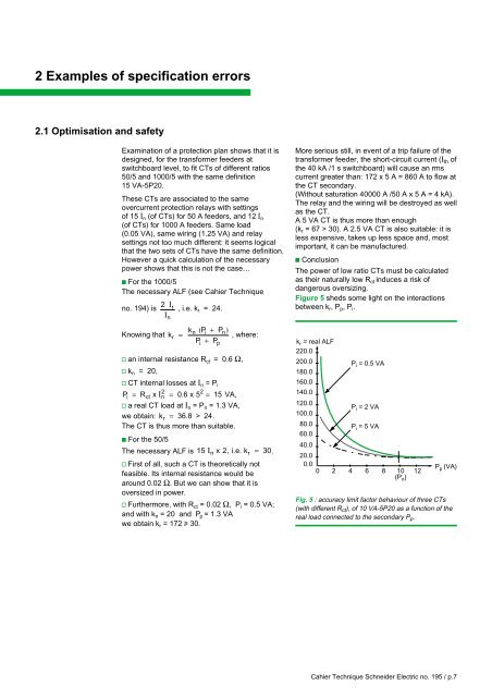
2 Examples of specification errors2.1 Optimisation and safetyExamination of a protection plan shows that it isdesigned, for the transformer feeders atswitchboard level, to fit CTs of different ratios50/5 and 1000/5 with the same definition15 VA-5P20.These CTs are associated to the sameovercurrent protection relays with settingsof 15 I n (of CTs) for 50 A feeders, and 12 I n(of CTs) for 1000 A feeders. Same load(0.05 VA), same wiring (1.25 VA) and relaysettings <strong>no</strong>t too much different: it seems logicalthat the two sets of CTs have the same definition.However a quick calculation of the necessarypower shows that this is <strong>no</strong>t the case…c For the 1000/5The necessary ALF (see <strong>Cahier</strong> Technique<strong>no</strong>. 194) is 2 I r , i.e. k r = 24.InK<strong>no</strong>wing that kr=kn ( Pi + Pn) , where:P + Pv an internal resistance R ct = 0.6 Ω,v k n = 20,v CT internal losses at I n = P iPi = Rct x In2 = 06 . x 5 2 = 15 VA,v a real CT load at I n = P n = 1.3 VA,we obtain: k r = 36.8 > 24.The CT is thus more than suitable.c For the 50/5The necessary ALF is 15 I n x 2, i.e. k r = 30.v First of all, such a CT is theoretically <strong>no</strong>tfeasible. Its internal resistance would bearound 0.02 Ω. But we can show that it isoversized in power.v Furthermore, with R ct = 0.02 Ω, P i = 0.5 VA;and with k n = 20 and P p = 1.3 VAwe obtain k r = 172 u 30.ipMore serious still, in event of a trip failure of thetransformer feeder, the short-circuit current (I th ofthe 40 kA /1 s switchboard) will cause an rmscurrent greater than: 172 x 5 A = 860 A to flow atthe CT secondary.(Without saturation 40000 A /50 A x 5A=4kA).The relay and the wiring will be destroyed as wellas the CT.A 5 VA CT is thus more than e<strong>no</strong>ugh(k r = 67 > 30). A 2.5 VA CT is also suitable: it isless expensive, takes up less space and, mostimportant, it can be manufactured.c ConclusionThe power of low ratio CTs must be calculatedas their naturally low R ct induces a risk ofdangerous oversizing.Figure 5 sheds some light on the interactionsbetween k r , P p , P i .k r = real ALF220.0200.0180.0160.0140.0120.0100.080.060.040.0P i = 0.5 VAP i = 2 VAP i = 5 VA20.00.00 2 4 6 8 10 12(P n )P p (VA)Fig. 5 : accuracy limit factor behaviour of three CTs(with different R ct ), of 10 VA-5P20 as a function of thereal load connected to the secondary P p .<strong>Cahier</strong> Technique <strong>Schneider</strong> <strong>Electric</strong> <strong>no</strong>. <strong>195</strong> / p.7