Method of Joints Worksheet
Method of Joints Worksheet
Method of Joints Worksheet

You also want an ePaper? Increase the reach of your titles
YUMPU automatically turns print PDFs into web optimized ePapers that Google loves.
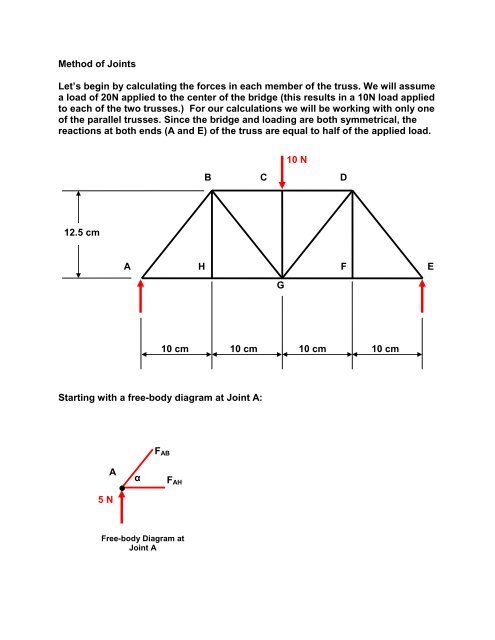
<strong>Method</strong> <strong>of</strong> <strong>Joints</strong>Let’s begin by calculating the forces in each member <strong>of</strong> the truss. We will assumea load <strong>of</strong> 20N applied to the center <strong>of</strong> the bridge (this results in a 10N load appliedto each <strong>of</strong> the two trusses.) For our calculations we will be working with only one<strong>of</strong> the parallel trusses. Since the bridge and loading are both symmetrical, thereactions at both ends (A and E) <strong>of</strong> the truss are equal to half <strong>of</strong> the applied load.10 NB C D12.5 cmAHFEG10 cm 10 cm 10 cm 10 cmStarting with a free-body diagram at Joint A:F ABA5 NαF AHFree-body Diagram atJoint A
Now that we have done the calculations, is member AH in tension orcompression? ___________________What about member AB? __________________________________Our final answer should indicate whether the members are in tension orcompression.F AB = 6.4 N (C)F AH = 4.0 N (T)Now lets move on to Joint H and determine what direction the force F AH ispointing.F AHA HF AHHFrom this, we can see that the force from member AH should be pointing to theleft at pin H.The free-body diagram for Joint H is shown next.F BHGH AHFxF AH H F GHFree-body Diagram atJoint H F F Fy F GH =FBHF BH =Is F GH in tension or compression? __________________At joint H, we notice that F BH equals 0 N. This is called a zero-force member.Zero-force members are important in trusses for several reasons.
What are some <strong>of</strong> the reasons you can think <strong>of</strong>?Now let’s analyze Joint B. First, draw the free-body diagram in the space below.
ααF BCFx F cos( ) F cos( ) F 0AB BG BC ( ) FBG FBC 0 F AB6.4 NF BH0NF BGFyFBGsubstitute F into the second equation aboveBGFBCCheck for tension or compressionF BC =F BG =The only member left to solve for is CG. We can solve for it at joint C.Draw the free-body diagram and solve for F CG .F CG =
Now let’s calculate the expected failure load and location.Consider member AB, is this member in tension or compression? _____________From the data sheet, what is the expected failure load <strong>of</strong> member AB? _________From the method <strong>of</strong> joints analysis, what was the internal member force inmember AB for the design load <strong>of</strong> 10N? ____________In order to calculate the Factor <strong>of</strong> Safety (F.S.) for member AB use the equationbelow.Expected Failure LoadFS . . Internal Member Force___________________MemberInternal MemberForce (Newtons)Expected Failure Load(Newtons)F.S.AB, DE 6.4 (C) 56.8 8.9BC, CD8.0 (C)AH, EF 4.0 (T) 23.5* x 2 11.8BG, DG6.4 (T)GH, FG4.0 (T)CG10 (C)BH, DF 0 NA NA*Strength <strong>of</strong> tension members was experimentally determined to be 23.5N.
Where do you expect the truss to fail? ______________Calculate the expected failure load for the bridge:(F.S) x (number <strong>of</strong> parallel trusses) x (number <strong>of</strong> members at failure location) x (10 N) = _________Maximum load actually held by the bridge: _________________Member that failed: ______________