Trane Engineers Newsletter, vol 31-1
Trane Engineers Newsletter, vol 31-1
Trane Engineers Newsletter, vol 31-1

You also want an ePaper? Increase the reach of your titles
YUMPU automatically turns print PDFs into web optimized ePapers that Google loves.
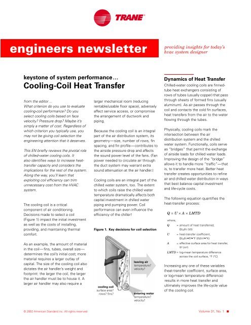
engineers newsletterproviding insights for today’shvac system designerkeystone of system performance…Cooling-Coil Heat Transferfrom the editor…What criterion do you use to evaluatecooling-coil performance? Do youselect cooling coils based on facevelocity? Pressure drop? Maybe it’ssimply a matter of cost. Regardless ofwhich criterion you typically use, youmay not be giving coil selection theengineering attention that it deserves.This EN briefly reviews the pivotal roleof chilled-water cooling coils. Italso identifies ways to increase heattransfercapacity and considers theimplications for the rest of the system.Along the way, you’ll learn thatexploiting coil efficiency can trimunnecessary cost from the HVACsystem.The cooling coil is a criticalcomponent of air conditioning.Decisions made to select a coil(Figure 1) impact the initial investmentas well as the costs of installing,providing, and maintaining thermalcomfort.As an example, the amount of materialin the coil—fins, tubes, overall size—determines the coil’s initial cost; morematerial requires a larger outlay ofcapital. The size of the cooling coil alsodictates the air handler’s weight andfootprint: the larger the coil, the largerthe air handler must be to house it. Alarger air handler may also require alarger mechanical room (reducingrentable/usable floor space), adverselyaffect service access, or compromisethe arrangement of ductwork andpiping.Because the cooling coil is an integralpart of the air distribution system, itsgeometry—size, number of rows, finspacing, and fin profile—contributes tothe airside pressure drop and affectsthe sound power level of the fans. (Fanpower needed to circulate air throughthe duct system may warrant extrasound attenuation at the air handler.)Cooling coils are an integral part of thechilled water system, too. The extentto which coils raise the chilled watertemperature dramatically affects bothcapital investment in chilled waterpiping and pumping power. Coilperformance can even influence theefficiency of the chiller!Figure 1. Key decisions for coil selectionDynamics of Heat TransferChilled-water cooling coils are finnedtubeheat exchangers consisting ofrows of tubes (usually copper) that passthrough sheets of formed fins (usuallyaluminum). As air passes through thecoil and contacts the cold fin surfaces,heat transfers from the air to the waterflowing through the tubes.Physically, cooling coils mark theintersection between the airdistribution system and the chilledwater system. Functionally, coils serveas “bridges” that permit the exchangeof airside loads for chilled water loads.Improving the design of the “bridge”allows it to handle more “traffic”—thatis, to transfer more heat. Better heattransfer creates opportunities to refineair and chilled water distribution in waysthat best balance capital investmentand life-cycle costs.The following equation quantifies theheat-transfer process:Q = U × A × LMTDwhere,Q = amount of heat transferred,Btu/hr (W)U= heat-transfer coefficient,Btu/hr•ft²•°F (W/m²•°K)A = effective surface area for heat transfer,ft² (m²)LMTD = log-mean temperature differenceacross the coil surface, °F (°C)Increasing any one of these variables(heat-transfer coefficient, surface area,or log-mean temperature difference)results in more heat transfer andultimately improves the life-cycle valueof the cooling coil.© 2002 American Standard Inc. All rights reserved Volume <strong>31</strong>, No. 1 ■
Figure 4. Effect of supply air temperature on log-mean temperature differenceand water, but also the costs of movingthem.10°F ∆T waterside, 25°F ∆T airside:28 – 13LMTD =ln --------------------------- =( 28 ⁄ 13)19.6152 provided the additional heattransfer needed to reach 52°F. Not onlywas the airside pressure drop less, butthe lower face velocity also alleviatedconcerns about moisture carryover.In this case, improving heat-transferperformance and selecting the coilsbased on a closer approach (TD 1 )reduced the required airflow by15 percent…and yielded annual fanenergysavings of almost $12,000 USD.10°F ∆T waterside, 28°F ∆T airside:28 – 10LMTD =ln --------------------------- =( 28 ⁄ 10)17.5Closing ThoughtsQ = U × A × LMTD reminds us ofthe extent to which we preordain thecapital and life-cycle costs of an HVACsystem. Specifying the entering waterand leaving air temperatures that allcooling coils must meet not onlydetermines the required mass of airThe next time that you select a coil,invest a few extra minutes to explorethe LMTD effect with lower chilledwater temperatures and colder supplyair. You’ll find that the potential benefitsare simply too attractive to ignore. ■By Don Eppelheimer, applicationsengineer, and Brenda Bradley,information designer, <strong>Trane</strong>.You can find this and other issuesof the <strong>Engineers</strong> <strong>Newsletter</strong> in thecommercial section of www.trane.com.To comment, send a note to <strong>Trane</strong>,<strong>Engineers</strong> <strong>Newsletter</strong> Editor,3600 Pammel Creek Road, La Crosse,WI 54601-7599, or e-mail us atcomfort@trane.com.Note: Improving coil efficiency byreducing airflow offers two benefits—it requires less fan horsepower and itreduces the cooling load (via less fanheat). Of course, cooler air may requiremore reheat. A detailed energy analysisshould be performed to assess theeconomic impact on the entire HVACsystem and, ultimately, on buildinglife-cycle costs.Figure 5. Supply air temperature versus annual fan energy consumptionDesign Parameters Before AfterCoil rows 4 4fin spacing 124 152 fins/ftface velocity 552 469 ft/minAirside LAT 55°F 52°Fflow <strong>vol</strong>ume 55,385 47,077 ft³/minpressure drop 0.62 0.56 in. wgWaterside EWT 42°F 42°Fflow <strong>vol</strong>ume 222 219 gal/minpressure drop <strong>31</strong>.7 30.9 ft of waterLAT = leaving-coil air temperatureEWT = entering-coil water temperatureEnergy savings were projected with <strong>Trane</strong>’sSystem Analyzer software (version 5.08.09), andare based on a 400,000 ft² building and variable<strong>vol</strong>umeair distribution.An American Standard Companywww.trane.comFor more information, contact yourlocal district office or e-mail us atcomfort@trane.com<strong>Trane</strong> believes the facts and suggestions presented here to be accurate. However,final design and application decisions are your responsibility. <strong>Trane</strong> disclaimsany responsibility for actions taken on the material presented.■ 4 ADM-APN002-EN