Mixed Flow Relative Humidity Generator - ResearchGate
Mixed Flow Relative Humidity Generator - ResearchGate
Mixed Flow Relative Humidity Generator - ResearchGate

Create successful ePaper yourself
Turn your PDF publications into a flip-book with our unique Google optimized e-Paper software.
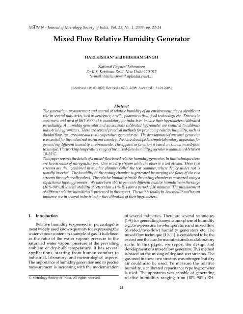
MAPAN - Journal of Metrology Society <strong>Mixed</strong> of <strong>Flow</strong> India, <strong>Relative</strong> Vol. 23, <strong>Humidity</strong> No. 1, 2008; <strong>Generator</strong> pp. 21-24<strong>Mixed</strong> <strong>Flow</strong> <strong>Relative</strong> <strong>Humidity</strong> <strong>Generator</strong>HARI KISHAN* and BHIKHAM SINGHNational Physical LaboratoryDr K.S. Krishnan Road, New Delhi-110 012*e-mail : hkishan@mail.nplindia.ernet.in[Received : 06.03.2007; Revised : 07.01.2008; Accepted : 31.01.2008]AbstractThe generation, measurement and control of relative humidity of an environment play a significantrole in several industries such as aerospace, textile, pharmaceutical, food technology etc. Due to theawareness and need of ISO-9000, it is mandatory for industries to have their hygrometers calibratedperiodically. A humidity generator and an accurate calibrated hygrometer are required to calibrateindustrial hygrometers. There are several practical methods for producing relative humidity, such asdivided flow, two-pressure and two-temperature generator etc. The development of one such generatoris essential for the industrial use in our country. We have developed a simple laboratory apparatus forgenerating different humidity environments. The apparatus function is based on known mixed-flowtechnique. The working temperature range of the mixed-flow humidity generator is maintained between18-25ºC.This paper reports the details of a mixed-flow based relative humidity generator. In this technique thereare two streams of nitrogen/air gas. One is a dry stream while the other is a wet stream. These twostreams are then combined in another chamber called the test chamber, where device under test isusually inserted. The humidity in the testing chamber is generated by varying the flows of the twostreams through needle valves. The relative humidity inside the testing chamber is measured using acapacitance type hygrometer. We have been able to generate different relative humidities in the range(10%-90%)RH, with stability of better than ±1 % RH over a period of 30 minutes. The measurementof different relative humidities is presented in this report. The unit is totally in-house built and has animmense use in several industries for the calibration of their hygrometers.1. Introduction<strong>Relative</strong> humidity (expressed in percentage) ismost widely used known quantity for expressing thewater vapour content in a sample of gas. It is definedas the ratio of the water vapour pressure to thesaturated water vapour pressure at the prevailingambient or dry-bulb temperature. It has severalapplications, starting from human comfort toindustrial, laboratory, and meteorological aspects.The importance of humidity generation and its precisemeasurement is increasing with the modernization© Metrology Society of India, All rights reserved.of several industries. There are several techniques[1-9] for generating known atmosphere of humiditye.g., two-pressure, two-temperature and mixed flow(divided/two-flow) humidity generators etc. Themixed flow technique [10-11] is considered to be theeasiest one that can be manufactured on a laboratoryscale. In this paper, we report the design anddevelopment of a mixed flow generator. This methodis based on the mixing of dry and wet streams. Thegas used in these two streams was nitrogen but dryair could also be used. To measure the relativehumidity, a calibrated capacitance type hygrometeris used. The apparatus was capable of generatingrelative humidities ranging from (10%-90%) RH.21
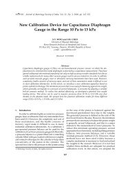
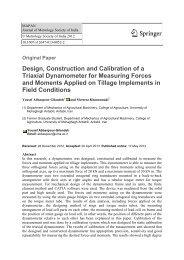
Hari Kishan and Bhikham SinghTesting showed that the produced RH% is stable inrange of (10%-90%)RH at least for over the period of30 minutes, hence the developed apparatus is reliableand well suited for the calibration of industrial lowgradehygrometers in the above mentioned range. Therelative humidity is found to be slightly unstable(± 2%) above 90% RH, hence we would like to suggestthe use of our generator up to 90% RH.2. ExperimentalFig. 1 shows schematically the in-house developedmixed flow relative humidity generator. This systemconsists of a dry nitrogen gas supply (cylinder) withNeedlevalve-1SensorRHMeasurementdeviceNitrogengas sourceNeedlevalve-2SaturatorMixingchamberTestchamberFig. 1. Schematic diagram of mixed flow humidity generatorFig. 2. Variation of relative humidity [RH(%)], dew-point temperature [t d(ºC)] and dry-bulb temperature [t(ºC)]versus time; RH(%)O, t d(ºC)Δ, t( o C)22
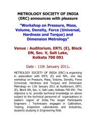
<strong>Mixed</strong> <strong>Flow</strong> <strong>Relative</strong> <strong>Humidity</strong> <strong>Generator</strong>a pressure regulator, two needle valves, three coppercontainers and a relative humidity indicator/transmitter (capacitance type hygrometer). The firstcontainer contains distilled water at roomtemperature. The saturated gas from the first containeris mixed with the dry gas into the second container,called as mixing chamber. The relative humiditysensor is inserted in the third container, known as thetest chamber. The nitrogen gas is divided into twostreams using the needle valves. One of the stream issaturated by bubbling in the distilled water, which isknown as the wet metal bubbler. The dry gas goesinto the second container; wherein both streams mix,this container is known as the mixing chamber. Therequired relative humidity is generated, by controllingthe mixing ratio of the dry nitrogen stream and thewet one. The generated relative humidity, dew-pointand dry-bulb temperatures are measured by thecapacitance type hygrometer in the test chamber. Wehave been able to generate different relative humiditiesin the range of (10%-90%)RH with stability better than± 1 % RH over a period of 30 minutes. The workingtemperature range of the mixed-flow humiditygenerator is generally maintained between 18-25ºC.3. Results and DiscussionFigs. 2, 3 and 4 display the observed variation ofrelative humidity [RH(%)], dew-point temperature[t d(ºC)] and dry-bulb temperature [t(ºC)] versus timeby this mixed-flow technique. Fig. 2 shows the lowRH (~ 10%), while Figs. 3 and 4 show the medium RH(~ 50%) and high RH (~ 95%) respectively. Thesemeasurements are being taken at an interval of oneminute with the help of a capacitance type hygrometer(Model Testo-650 from Germany), which wascalibrated by us against our reference standard witha periodicity of twice a year. The overall uncertaintyof the capacitance hygrometer was found to be ± 2%RH. From the graphs, it is seen that the generatedrelative humidity is stable within ± 1% over a durationof 100 minutes. Further, we checked the stability ofRH% over 5-10 runs. Hence our apparatus can beused as a transfer standard for the calibration ofindustrial low-grade hygrometers. This device iscomparably simple in fabrication to other twopressure/two-temperaturetechniques based relativehumidity generators.4. ConclusionThis generator is totally in-house built,inexpensive and can be used very conveniently in thelaboratory for the calibration of low-gradehygrometers. The generator is capable of producingrelative humidity in the range (10%-90%) with stabilityFig. 3. Variation of relative humidity [RH(%)], dew-point temperature [t d( o C)] and dry-bulb temperature [t( o C)]versus time; RH(%)O, t d( o C)Δ, t( o C)23
Hari Kishan and Bhikham SinghFig. 4. Variation of relative humidity [RH(%)], dew-point temperature [t d(ºC)] and dry-bulb temperature [t(ºC)]versus time; RH(%)O, t d( o C)Δ, t( o C)better than ± 1% RH. The working range of temperatureis between 18-25 ºC with a stability better than± 0.2 ºC. This generator is quite accurate, reliable andstable for more than 30 minutes for continuoushumidity generation. It has immense application inthe industry for their in-house calibration ofhygrometers. For future endeavors we need to stabilizethe produced RH% at higher than 90% to the stabilityof ± 1% RH. It is planned to estimate the expandeduncertainty of measurement of RH which will bereported in a future article.AcknowledgementThe authors express their sincere gratitude to theDirector NPL, New Delhi, for his valuable guidance,constant encouragement and keen interest in thepresent work. Thanks are also due to others colleaguesof Cryogenics and Superconductivity division and Mr.Shiv Dutt Sharma in particular, for their kind help inseveral ways in the successful completion and testingof mixed-flow relative humidity generator.References[ 1] A. Wexler and D.D. Raymond, Pressure<strong>Humidity</strong> Apparatus, J. Res. Natl. Bur. Std., 48(1952) 269.[ 2] A. Wexler, Calibration of <strong>Humidity</strong>-MeasuringInstruments at the National Bureau ofStandards, ISA Transaction, 7 (1968) 356-362.[ 3] T. Inamatsu, Establishment of <strong>Humidity</strong>Standard in Japan, Bull NRLM, 44 (1995) 107-113.[4] M. Stevens and S.A. Bell, The NPL Standard<strong>Humidity</strong> <strong>Generator</strong>: an Analysis of Uncertaintyby Validation of Individual ComponentPerformance, Meas. Sci. Technol, 3 (1992) 943-952.[5] A Guide to the Measurement of <strong>Humidity</strong>,Published by The Institute of Measurement &Control, London, (1996).[6] H.S. Nham and KRISS (Republic of Korea)Private Communication.[7] S. Herforth, General Eastern USA, PrivateCommunication.[8] General Eastern's <strong>Humidity</strong> Handbook,Document No. A40103384 (1993).[9] M. Heinonen, The CMA <strong>Humidity</strong> Standard,Measurement, 17 (1996) 183-188.[10] F. Preusser, GCI Scientific Program Report, 1989.[11] Hari Kishan, R.B. Saxena and Shin Maekawa,<strong>Humidity</strong> Control in a Gas Using Divided <strong>Flow</strong>Technique, MAPAN-JMSI, 12 (1997) 123-126.24