Characterization of Universal Testing Machine before Calibration ...
Characterization of Universal Testing Machine before Calibration ...
Characterization of Universal Testing Machine before Calibration ...
- No tags were found...

You also want an ePaper? Increase the reach of your titles
YUMPU automatically turns print PDFs into web optimized ePapers that Google loves.
AdMet 2012 Paper No. FM 003<strong>Characterization</strong> <strong>of</strong> <strong>Universal</strong> <strong>Testing</strong> <strong>Machine</strong> <strong>before</strong><strong>Calibration</strong> and its EffectMake Sure the UTM Fits the Application – <strong>Calibration</strong> and <strong>Testing</strong>Anuj GargAffiliation, Naimex 59H(A), NSEZ, Noida, Phase II, UPE-mail : anuj.garg@aimil.comAbstract : It is the responsibility <strong>of</strong> the calibration technician to confi rm the suitability <strong>of</strong>the verifi cation apparatus for the required calibration. The verifi cation apparatus shouldbe visually checked prior to use for proper working and visual inspection to ensure surethat the calibration has not been affected by transport etc. All apparatus must carry avalid calibration certifi cate to the relevant standard issued by an accredited laboratory.The calibration apparatus should be attached to both the moving crosshead and a fi xedpart <strong>of</strong> the machine such that the displacement <strong>of</strong> the crosshead is Uniaxial. Thereshould not be any lateral play in cross head to ensure the axial Loading.The loading platens are either permanently installed in the machine or they are specifi ccomponents <strong>of</strong> the testing machine. The loading platens should be verifi ed to performtheir function in accordance with the requirements <strong>of</strong> the testing machine.Movement <strong>of</strong> loading assembly should be smooth and jerk free to ensure proper loading.We have to ensure that there is no leakage in loading system.Keywords: Force, UTM, Stiffness, <strong>Calibration</strong> etc.INTRODUCTIONThe basic machine consists <strong>of</strong> twocomponents; a Load Frame and ControlConsole with Hydraulic Power Unit which areinterconnected by hydraulic and electricallines. The Load frame is <strong>of</strong> the two testtype one the Tensile Test and other theCompression Test. The Tensile Test can beperformed in the upper part <strong>of</strong> the Load Frameand Motorised Crosshead at a suitable heightwhich is suitable for fi xing test specimen andremoval <strong>of</strong> test specimen. Some <strong>Machine</strong>shave semi-open or open crosshead with leveroperated grips. Alternative grips can also beprovided. The Compression test can only beperformed in the lower area <strong>of</strong> the Load Framebetween the weighing table and the underside<strong>of</strong> the motorized crosshead using hard endedCompression platens. Some <strong>of</strong> the machinesare also provided only for the CompressionTest and without a crosshead.Preliminary Installation : Always referto manufacturer Foundation and assemblyDiagrams. To get optimum results, the followingsteps must be adhered.• The location <strong>of</strong> machine should befree from any kind <strong>of</strong> vibration and theAtmosphere should be free <strong>of</strong> acidic orany containments that could acceleratecorrosion to <strong>Machine</strong>d surfaces andelectrical contacts and electroniccomponents.• Depending upon the capacity/type <strong>of</strong>test to be conducted, the foundation hasto be prepared to ensure that it is intact.Make sure High Tensile bolts are used infoundation.1
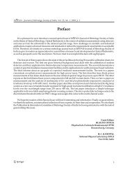
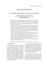
• The machine should be kept in such afashion that allows a minimum clearance<strong>of</strong> 2 feet at the sides and at the rearfor working space during testing andcalibration.• All machined surfaces which have beencoated with a rust preventive coatingshould be cleaned. Trichloroethyleneor any suitable non-corroding solventshould be used for this purpose.Periodically, the machined surfacesshould be wiped with a clean, oil soakedcloth to minimize corrosion.• Assemble the Top crossheadand columns with weighing tableappropriately. A typical example forAssembly is shown in diagram for properassembly <strong>of</strong> Top cross head and columnwith weighing Table.Figure 2environmental chambers that could requireadditional space in both directions.Figure 1Selection <strong>of</strong> Load-Frame : The selection <strong>of</strong>load frame capacity is based on the maximumforce required to cause the material beingtested to break or fracture. Specifi cations forUTM/CTM load frame capacity and dimensionsare vital to the equipment-selection process.Dimensional specifi cations must take intoconsideration clearances between columnsand vertical clearance to adequately handlethe products being tested. Some materials,such as elastomers and s<strong>of</strong>t polymers willelongate substantially, and suffi cient verticaltravel must be available to allow the materialto stretch as far as necessary without runningout <strong>of</strong> travel. Also, consideration shouldbe given to any special grips, fi xtures and2Frame Stiffness : In some instances,frame stiffness is a feature that can beoverrated. The stiffness <strong>of</strong> the test frame couldbe an important factor where only crossheadmotion is being used instead <strong>of</strong> a separateextensometer or defl ection-measuringdevice. Most applications that comply withinternational tensile-testing standards callfor the use <strong>of</strong> an extensometer or defl ectionmeasuringdevices.There are many machine components thatcan affect the frame stiffness including screwdiameter, ball-nut fi t, crosshead stiffness,screw-bearing fi t and frame stiffness (Fig. 3).In addition, compliance <strong>of</strong> the specimen itself,pull rods and the specimen-gripping devicesalso contribute to errors.Drive-System Specifications : Theseimportant specifi cations ensure that thesystem complies with the relevant internationalstandards. Lateral motion is important and is
explained in detail. Speed accuracy, positionresolution, position accuracy and repeatabilityall constitute important specifi cations forconsideration.Polymer material-testing speeds can vary(depending on the type <strong>of</strong> polymer) from 0.08to 2 in./min (2 to 50 mm/min). Elastomers dorequire high speeds, but they very seldomdemand full load at those speeds.<strong>Testing</strong>-Control Electronics : Designingtesting equipment the presents problem <strong>of</strong>trying to design something as completelyand comprehensively as possible, butdoing so without making the hardware sosophisticated that it becomes diffi cult to repairand/or unaffordable. For example, some UTMequipment might include a control console,a computer, interface boards and signalconditioners, depending on the accessoriesto be used. In an optimized design, on theother hand, the fewer components a systemincorporates, the fewer the parts that can failand the fewer the chances are <strong>of</strong> somethinggoing wrong.Figure 3Note: 1 UTM components that can be asource <strong>of</strong> errors includes screw diameter, ballnutfi t, crosshead stiffness, screw bearing fi tand frame stiffness.Lateral Motion : Lateral motion possiblyis even more important than frame stiffness.Lateral motion <strong>of</strong> the crosshead can be aserious source <strong>of</strong> error because it introducesbending motion into the test specimen.Mixing bending into a tensile test will causethe specimen to fail at a lower s than normalStress.Maximum Speed at Full Load : Maximumspeed at full load is also an importantspecifi cation. Many UTMs are claimed to becapable <strong>of</strong> operating at full speed and at fullforce. However, it is questionable whether thisis desirable, particularly using high-capacitymachines (e.g., 100 kN and over). Most steeltensile-testing standards call for testing atload speeds less than 2 in./min (50 mm/min).3Figure 4DO’S and Don’ts for Proper Operation• Make sure that oil Temperature doesnot raise more than 50 Deg C. This isrequired to stablies the force applied.There should be a provision for Air typeoil cooler.• Don’t use the Motorized Cross Head toapply Load on the specimen.• Don’t forget to remove the test handleonce test is started.• Make sure Wedge grips are periodicallylubricated.
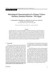
• Make sure that the Specimen is grippedproperly in the top and lower grips asshown in the fi gures below. This fi gureshows the proper grip set-up for testingthin specimens where the proper amount<strong>of</strong> liners have been inserted behind thewedge grips, so that the smaller edge<strong>of</strong> the grips are kept at least a 1/2 inchinside the crosshead during the test.THIS IS VERY IMPORTANT. With theproper precautions taken, expensivedamage to grips and crossheads can beprevented.Figure 5This fi gure 6 shows an improper grip setupwhere the full gripping surfaces <strong>of</strong> the wedgegrips are NOT BEING utilized. The grips bitinginto the short grip ends <strong>of</strong> the specimen willcause the specimen ends to be crushed,producing a stress concentration that couldbreak the wedges inside the crosshead. Thistype <strong>of</strong> condition will also allow the open ends<strong>of</strong> the wedges to slant in, jamming the wedgesand damaging the teeth on Rack & PinionGrips.Figure 6Selecting UTM can mean digging throughAIMIL- Tinius Olsen Options amongst variousmanufacturers worldwide.Force-Measurement System: Thissystem calls for accuracy and repeatability. Anaccuracy <strong>of</strong> ±1% <strong>of</strong> reading to 1% <strong>of</strong> capacity,and a repeatability <strong>of</strong> 0.25% <strong>of</strong> reading covers95% <strong>of</strong> all applications. Self-identifying load4cells can be convenient when multiple loadcells are to be used on one system.Strain-Measurement System: Mostinternational standards, such as ISO,ASTM, JIS, DIN, BS, etc., contain similarspecifi cations for strain measurement.Accuracy should be 0.5 μm, repeatability0.25 μm and resolution 0.0004% <strong>of</strong> range.In selecting a strain-measurement system, itshould be verifi ed that the specifi cations meetthe corresponding standards.Automatic <strong>Calibration</strong>: A single click<strong>of</strong> the mouse for an automatic calibrationfunction is really a single point check <strong>of</strong> thereadout system. This is done through s<strong>of</strong>twarewithout any error. The defi nition <strong>of</strong> calibrationstates that the device being calibrated is to becompared with a traceable standard source<strong>of</strong> the quantity being measured. Traceablestandards can be weights, calibration ringsand load cells. The process <strong>of</strong> auto calibrationmeans, in effect, that a control in the readoutdevice is provided to allow adjustment. Thiscan create a risky situation where that controlcan be accidentally adjusted while usingthe machine. This could potentially result inerroneous data. An alternative philosophyis to make the system very stable andallow no adjustments except by a qualifi edcalibration technician using proper standardsfor comparison. Hence a calibration moduleis secured through a password to avoid anyaccidental adjustment in calibration.Conclusion : Trying to read through thelarge amount <strong>of</strong> information about equipmentfeatures, characteristics and specifi cationsto decide which are useful and relevant tothe particular application can be a toughtask. Although it is important not to purchaseequipment at very high prices but it is alsonot to compromise on quality, reliability, andservice and production-downtime factors justbecause <strong>of</strong> price <strong>of</strong> equipment. We at AIMILare committed to serve Customers to themaximum extent <strong>of</strong> their satisfaction and toprovide Customer with most value for theirmoney.