Installation of egegom Microducts - Egeplast
Installation of egegom Microducts - Egeplast
Installation of egegom Microducts - Egeplast
- No tags were found...

You also want an ePaper? Increase the reach of your titles
YUMPU automatically turns print PDFs into web optimized ePapers that Google loves.
How to work with®<strong>Microducts</strong>
CONTENT1. The company 32. Facts about the MicroductlinerProduct for outside telecommunicationsapplications; FttX, FttH 43. Produkte aus dem Lieferprogramm3.1 ege-com ® Microduct Mono di direct install 53.2 ege-com ® Microduct Mono db for layingdirectly in the ground 64. ege-com ® x way Microduct MultiGeneral 74.1 Articles 84.2 Packing + Storage 84.3 Technical Specification 94.4 How to work with ege-com ® Microduct Multi x way 104.4.1 Stripping tools 104.5 Instruction Manual for Stripping114.5.1 Setting up the depth <strong>of</strong> incision114.5.2 Precutting <strong>of</strong> the thin, flexible sheathing <strong>of</strong> the pipe tosecure the bundle <strong>of</strong> pipes 124.5.3 Precutting the firm and calibrated sheathing 134.5.4 Remove the outer sheath 144.6 Cutting <strong>of</strong> ege-com ® <strong>Microducts</strong> 164.7 How to mount a connector 174.8 <strong>Installation</strong> Aspects 185. Technical Specifications5.1 Raw Material 195.2 Other tensile forces 19
The company1. The companyAnybody searching for premium quality, competent advice and cost efficiency will find ahigh performance supplier and partner in egeplast. egeplast is currently one <strong>of</strong> the leadingmanufacturers <strong>of</strong> PE pressure pipes and telecommunications pipes in Europe. The productrange caters for the entire underground pipe infrastructure: pipes for drinking water,wastewater, gas and telecommunications. All pipes are produced at our factory in Greven(Germany). egeplast is a specialist in the development and production <strong>of</strong> pipes with protectiveand test properties used in trenchless installation as well as for microduct systems laiddirectly in the ground or for direct installations.
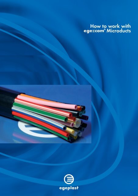
Facts about the Microductliner2. Facts about the MicroductlinerProducts for outside telecommunication applications;FttX, FttH (Fibre-to-the-Home)The ege-com ® Microduct Multi from egeplastis a bundle <strong>of</strong> pipes for laying directly in theground or for direct installation. Thanks toits special properties it is ideally suited to theuse <strong>of</strong> injection methods.Features• Robust, with high resistance to mechanicalstress• Excellent properties for injecting cablesinto microducts• High pressure resistance• Easy to install round corners and veryflexible• Simple connectorsSystem provider egeplast: Microduct System (d.i.) and (d.b.)Accessories on request:Straight connector 8/3.5 mmStraight connector 14/10 mmConnectorsEnd capsGas blockReducersSealing elementsJunction boxesTiesToolsHouse connectionsegeplast sealing systemegeplast sealing system
Other products from the product range3.1 ege-com ® Microduct Mono didirect installTechnical specificationsege-com ® Microduct Mono di – direct installSizeDimension[mm]OD[mm]Tolerance[mm]S[nominal]ID[mm]Max. Tensileforceduringinstallationat 20 °C[N]Min.bendingradiusat 20 °C[mm]Max.blowingPressure[bar]PressureBurst[bar]MetersPr. Drums0 / + 1%4/3 4 x 0.5 45/3.5 5 x 0.75 57/5.5 7 x 0.75 710/8 10 x 1.0 1012/10 12 x 1.0 1212 / 9.6 12 x 1.2 1216/12 16 x 2.0 1618/14 18 x 2.0 18-0.05+0.05-0.05+0.05-0.05+0.14-0.05+0.14-0.05+0.14-0.05+0.14-0.05+0.14-0.05+0.300.5 > 2.8 40 80 10 > 30 –0.75 > 3.35 80 100 10 > 30 –0.75 > 5.25 100 140 10 > 30 40001.0 > 7.75 200 200 10 > 30 33001.0 > 9.75 270 240 10 > 30 23001.2 > 9.35 320 240 10 > 30 23002.0 > 11.75 790 320 10 > 30 10002.0 > 15.75 900 360 10 > 30 **ColourcodeThe duct can be in either soild colours or natural with a colured stripe.
Other products from the product range3.2 ege-com ® Microduct Mono dbLaying directly in the groundTechnical specificationsege-com ® Microduct Mono db – direct installSizeDimension[mm]OD[mm]Tolerance[mm]S[nominal]ID[mm]Max. Tensileforceduringinstallationat[N]Min.bendingradiusat[mm]Max.blowingPressure[bar]PressureBurst[bar]MetersPr. Drums0 / + 1%7/4 7 x 1.5 78/3.5 8 x 2.25 810/6 10 x 2.0 1012/8 12 x 2.0 1214/10 14 x 2.0 1416/10 16 x 3.0 16-0.05+0.14-0.05+0.14-0.05+0.14-0.05+0.14-0.05+0.14-0.00+0.301.5 > 3.85 210 140 16 > 50 40002.25 > 3.35 330 160 16 > 50 35002.0 > 5.75 500 200 16 > 50 33002.0 > 7.75 600 240 16 > 50 23002.0 > 9.75 700 280 16 > 50 17003.0 > 9.20 1000 320 16 > 50 1000ColourcodeThe duct can be in either soild colours or natural with a colured stripe.
®x way Microduct MultiTechnical spezification4. ege-com ® x way Microduct MultiGeneralConstruction•OutersheathPOwithdifferentcolours•InnerLinerMicroductMonowithlowfrictionlayerProduct Performance•BENDING>0xdiameter<strong>of</strong>ductat0°C•UVSTABILIZED–yesColourcodeTheoutersheathcanbeineithersoildcolourswithacoluredstripeRAL300BrightredRAL004PureorangeRAL9004BlackColourcode stripeRAL300BrightredRAL9010PurewhiteRAL101RapeseedyellowRAL5015SkyblueRAL6001EmeraldgreenRAL4005Blue-lilacRAL8011Nussbraun7
Articles / Packing + Storage4.1 ArticlesMicroduct Multi 2 x-way24-way 5/3Microduct Multi x -wayMicroduct Multi4.2 Packing + StorageTyp <strong>of</strong>DrumsGH(mm)K[mm]GB[mm]I[mm]EW[mm]Basicweight[kg]1401 S 2800 1200 1100 125 1020 2301402 S 2800 1200 1600 125 1520 2501403 H 1200 485 440 80 400 29.51404 H 1800 900 1000 100 920 300S = Steel drum; H = Wooden drumThe ends <strong>of</strong> the tubes are sealed to prevent the ingress <strong>of</strong> water or dirt (End caps).
®x way Microduct MultiTechnical Specification4.3 Technical specification ege-com ® x way Microduct Multiege-com ® x way Microduct Multi 14 mmway<strong>of</strong>pipeDimension(Nominal)[mm]Size<strong>of</strong>pipe[OD/ID]MaxTensileforceduringinstallationat0°C[N]Minbendingradiusat0°C[mm]Typ<strong>of</strong>DrumsMetersPrDrums0/+1%way 95x06 14/10 1000 560 1404H* 14006way 440x06 14/10 3000 880 1404H* 9507way 440x06 14/10 3000 880 1404H* 950ege-com ® x way Microduct Multi 12 mmway<strong>of</strong>pipeDimension(Nominal)[mm]Size<strong>of</strong>pipe[OD/ID]MaxTensileforceduringinstallationat0°C[N]Minbendingradiusat0°C[mm]Typ<strong>of</strong>DrumsMetersPrDrums0/+1%3way 65x10 1/8 100 530 1401S* 5005way 407x15 1/10 960 814 1401S* 5007way 397x10 1/8 3000 794 1401S* 500ege-com ® x way Microduct Multi 7 mmway<strong>of</strong>pipeDimension(Nominal)[mm]Size<strong>of</strong>pipe[OD/ID]MaxTensileforceduringinstallationat0°C[N]Minbendingradiusat0°C[mm]Typ<strong>of</strong>DrumsMetersPrDrums0/+1%6way 35x10 7/4 900 470 1401S* 350010way 94x10 7/4 1500 588 1401S* 35004way 43x10 7/4+1x14/10 3500 864 140S* 500ege-com ® x way Microduct Multi 5 mmway<strong>of</strong>pipeDimension(Nominal)[mm]Size<strong>of</strong>pipe[OD/ID]MaxTensileforceduringinstallationat0°C[N]Minbendingradiusat0°C[mm]Typ<strong>of</strong>DrumsMetersPrDrums0/+1%4way 400x33 5/35+1x10/8 3000 800 1401S* 500Thebenefits<strong>of</strong>theproductataglance:*=SeePage7fordrumsize•<strong>Microducts</strong>ystemcanbelaiddirectlyinthegroundupto4way+guidepipe•Innerpipesdonottwistandarestress-free•Stableandeasyinstallation•Simplerange<strong>of</strong>mouldedparts•Longinjectionlengthsthankstospecialpipematerials•Longservicelifeduetooptimalmaterialspecificationsand‘addedvalue’options9
How to work®Microduct Multi x waySupplementtotheinstallationinstructionsforPE-HDpipesA535fromKunstst<strong>of</strong>frohrverbandeVBonn4.4 How to work with ege-com ® Microduct Multi x way4.4.1 Stripping toolsJokariCable-KnifeArtNr:108643Da7-37mmArtNr:108644Da35-50mmWirecutterwithdistancepiece(6-67mm)ArtNr:110661CablestrippingknifeArtNr:108646CutterwithtriangularbladeArtNr:10864PeelingEquipmentM10N01ArtNr:103001Arange<strong>of</strong>pipecuttersisavailable10
Instruction Manual for Stripping4.5 Instruction Manual for Stripping4.5.1 Setting up the depth <strong>of</strong> incision for Microduct Multi x wayPicture 1 Picture 2The cutting depth <strong>of</strong> the knife can be manually adjusted with the knurled screw (Picture 2) at the end <strong>of</strong> the handle.Picture 3Picture 4Here it is important that the knife does not reach the Microduct because the duct would be damaged.Thereby the sheath won`t be cutted through completely.11
Instruction Manual for Stripping4.5.2 Precutting the thin, flexible sheathing to secure the bundle <strong>of</strong> pipesPicture 5 Picture 6 Picture 7The Cable-knife Art.Nr.: 108643 or 108644 (depends on OD) will be repeatedly turnedaround the ducts to scratch the sheath (Pictures 5/6).Picture 8Picture 9Picture 10The longitudinal cut (between the both cutting areas) can be scratched with the Cable-Knife Art.108643/108644 (Pictures 7/8) or be cutted with the Cable stripping knifeArt.:108646 (Pictures 9/10) (in a pit so that the ducts can`t be damaged).12
Instruction Manual for Stripping4.5.3 Precutting the firm and calibrated sheathingPicture 11 Picture 12 Picture 13The Cable-Knife Art.Nr.: 108644 will be repeatedly turned around the ducts to scratch the sheath (Picture 11). The longitudinal cut(between the both cutting areas) can be scratched with the Cable-Knife Art.: 108644 (Picture 12) or be cutted with the Peeling equipmentM10N01 Art.: 103001 (Picture 15).Picture 14Picture 15Important! While using the M10N01 (Picture15) it must be payed careful attention,that the knife is only turned so far that theducts will not be damaged.The Wire cutter with distance piece Art.Nr.: 110661 must be repeatedly turned aroundthe duct. Thereby the knife will be piecewise moved with the adjusting screw (Picture 13)until the distance piece (Picture 14).13
Instruction Manual for Stripping4.5.4 Remove the outer sheathTo remove the outer sheath the ducts have to be repeatedly bent up and down at thecutting areas (the outer sheath cracks at those areas).Afterwards the outer sheath can be removed from the ducts.Microduct Multi with 4 way / 7 way:Picture 16 Picture 17 Picture 18Picture 19 Picture 20Picture 2114
Instruction Manual for StrippingDepending on the design it may be necessary to slit the intermediate layer open afterremoving the outer layer <strong>of</strong> sheathing. The method is the same as that used for the outerlayer <strong>of</strong> sheathing.Picture 22 Picture 23To make the cut the pipe cutter is turnedround the intermediate layer several times(Fig. 19).In doing so it is important that the knife ispositioned so that it does not damage thepipes (see Fig. 1/2).The lengthwise cut (between the two cutareas) can be made using the insulatingstripping knife Art.:108646 (Fig. 20) (inan indentation so that the pipes are notdamaged).Picture 24Picture 25It is then possible to remove the intermediatelayer.15
Cutting <strong>of</strong>®<strong>Microducts</strong>4.6 Cutting <strong>of</strong> ege-com ® <strong>Microducts</strong>ThecutterwithtriangularbladeArtNr:10864canbeusedforcuttingthroughtheseveralege-com ® <strong>Microducts</strong>Picture6Picture7Picture8Picture916
How to Mount a Connector4.7 How to mount a connectorPlace the tool between the two outer pipes and gently push / turn a hole into the jacket.Then place the cutter under the pipe and cut. Remember to put an end cap on the end not in use.Picture 30 Picture 31 Picture 32Mount the pipe plough (Picture 30). The micropipe has to be beveled. It is important to bevel both pipes (Picture 31).Picture 33 Picture 34Cut open along the side - Mount the connector.Firmly press the pipe into the center<strong>of</strong> the connector until the lock releases (Picture33).Make a square opening in the jacket. Pullthe pipe to make sure that it is locked (Picture34).17
<strong>Installation</strong> Aspects4.8 <strong>Installation</strong> Aspects• Minimum bending during installation shall be > 20 x bundle Outer diameter at 20°C and >50 x bundle Outer diameter at -10 °C.• The bottom <strong>of</strong> the pipe trench has to be dug even and level. To avoid cavities and such in s<strong>of</strong>t areas, the bottom <strong>of</strong> the pipe trench hasto be completely stable and firm.• Final alignment (+/-2 cm. per meter) should be done by hand. If it is not possible to get the ground regular due to clay ground or stones,level the bottom with sand, gravel or other material free <strong>of</strong> stones.No damage or deterioration <strong>of</strong> the Microduct Multi X-way / tube shall occur during storage and operation without handling at temperaturerange from –10 up to +50°C.Ground for leveling should satisfy the following standard:• Ground may not be frozen• No sharp flint or other similar materialsIf the existing ground satisfies the above mentioned parameters, you can avoid digging a leveling layer.When the Microduct Multi X-way are being rolled out it is very important that the pipes arerolled out over the top <strong>of</strong> the drum and not underneath. This prevents the pipe from rollingitself up and instead it remains taught. To avoid traction damage, it is recommended to rollout the pipe in the pipe trench.The Microduct Multi X-way has to be tense in the pipe trench. Sun and heat will cause theplastic material to lengthen and the pipe will start to sprawl, which will complicate blowing.A forceful filling can result in an unfortunate pressure on the pipe, which can result ina friction filled blowing.After filling is complete, the ground has to be compressed to stabilize the pipe trench.Handling, laying and connecting the Microduct Multi X-way / tube shall be performedunder ambient temperatures <strong>of</strong> –10°C to +50°CFor cable installation blowing the temperature range is -5 °C to +35°CWhen the temperature difference between the Microduct Multi X-way / tube and the buriedprotective is more then 15°C, wait 8 hrs after installation before fixation <strong>of</strong> the bundle witha sealing or connectors.Note operation (blowing): ege-com ® <strong>Microducts</strong> ≤ 8 mm (Inner layer) without additionallubricant.Note on securing the individual pipes in the junction box:We recommend that inner pipes be secured n the junction box. In each case this willdepend on the junction box/microduct bundle system. Please discuss the systems usedwith us.18
Additional information5. Technical Specifications5.1 Raw MaterialQS 1Internal pressure creep80 °C – 170 Std. – Sigma4.5 MPaElongation at Break 350 %Yield Stress > 15 N / mm 2OIT (200 °C)> 20 min.Density kg/m 2 940 - 9605.2 Permissible tensile forcesOuterdiameterPermissible tensile force for telecommunications pipesmade from PE-HDTensile force:Permissible tensile force for telecommunicationspipes made from PE-HD at 20°Cambient temperatureNB:If the insertion time is > 10 h the valuesmust be reduced by 10%, and if the insertiontime is > 20 h values must be reducedby 20 %OD [mm] s [mm] F Zul.[KN] s [mm] F Zul.[KN]7 0.75 0.10 1.50 0.218 – – 2.25 0.3310 1.00 0.20 2.00 0.5012 1.00 0.27 2.00 0.6014 – – 2.00 0.7016 2.00 0.70 3.00 1.0020 2.00 0.90 – –25 – – 2.30 1.3032 2.00 1.50 3.00 2.1040 2.40 2.20 3.70 3.3050 3.00 3.50 4.60 5.2063 3.80 5.60 5.80 8.0075 4.50 7.90 6.80 11.0090 5.40 11.00 8.20 16.00110 6.30 16.00 10.00 25.00125 7.10 21.00 11.40 32.00140 8.30 27.00 12.70 40.00160 9.50 35.50 14.60 53.00180 10.70 45.00 16.40 67.00200 – – 18.20 83.00225 – – 20.50 105.00250 – – 22.70 129.00280 – – 25.40 162.00315 – – 28.60 205.00355 – – 32.20 261.00400 – – 36.30 331.0019
Data sheet egeplast Werner Strumann GmbH & Co. KGPlease contact the number below to obtain additional informationrelated to this Intruction sheet:egeplast Werner Strumann GmbH & Co. KGBusiness team FttHTel. nr.: + 49.2575.9710.100Your contact for products for telecommunications inGermany, Switzerland and Austria:egeplast pro cable GmbHAugust-Euler-Str. 350259 PulheimTel: +49.2238.3025 27Fax: +49.2238.3025 19E-Mail: info@procable.deYour contact for products for telecommunicaitonsoutside Germany:egeplast Werner Strumann GmbH & Co. KGRobert-Bosch-Straße 748268 GrevenTel: +49.2575.9710-0Fax: +49.2575.9710-110E-Mail: info@egeplast.deVisit our website: www.procable.deVisit our website: www.egeplast.deThis information does not contain warranty promises; Mistakes reserve. Information is obtained, which correspondsto the state <strong>of</strong> the art at the time <strong>of</strong> the production. It generally applies that necessary precautionarymeasures, standards, guidelines as well as otherwise relevant regulations must be considered.egeplast Werner Strumann GmbH & Co. KG - Robert-Bosch-Str. 7 - 48268 Greven, DeutschlandegeplastWerner Strumann Tel.: +49.2575.9710-0GmbH & Co. KG Fax: +49.2575.9710-110Robert-Bosch-Straße 7 info@egeplast.de48268 Greven, Germany www.egeplast.euege 1013 uk