JSR DPR300 Operator Manual - INSIDIX, Non-Destructive Testing
JSR DPR300 Operator Manual - INSIDIX, Non-Destructive Testing
JSR DPR300 Operator Manual - INSIDIX, Non-Destructive Testing

Create successful ePaper yourself
Turn your PDF publications into a flip-book with our unique Google optimized e-Paper software.
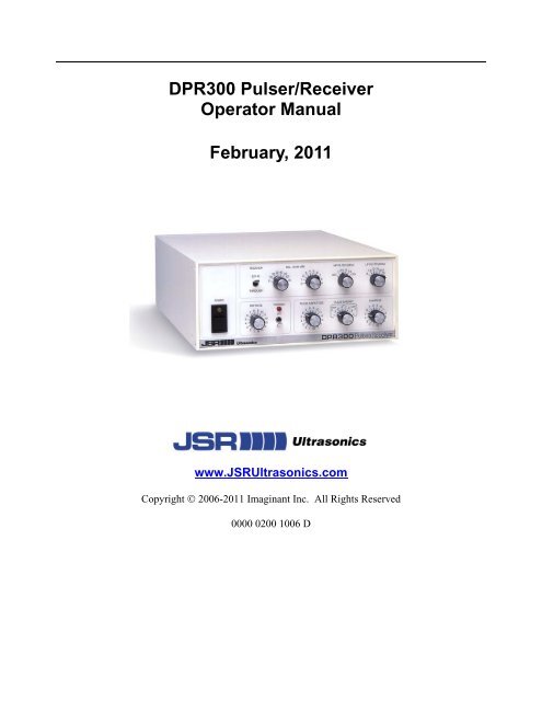
<strong>DPR300</strong> Pulser/Receiver<strong>Operator</strong> <strong>Manual</strong>February, 2011www.<strong>JSR</strong>Ultrasonics.comCopyright © 2006-2011 Imaginant Inc. All Rights Reserved0000 0200 1006 D
Table of Contents1 Fuse, Safety, and Technical Support Information ......................... 42 Fuse Information............................................................................... 42.1 Safety .........................................................................................................................................42.2 Technical Support ......................................................................................................................42.3 Cleaning .....................................................................................................................................43 Warranty Agreement ........................................................................ 53.1 Instrument Limited Warranty.....................................................................................................53.2 Software Limited Warranty .......................................................................................................53.3 Application Disclaimer ..............................................................................................................54 General Description.......................................................................... 64.1 Description.................................................................................................................................64.2 Physical......................................................................................................................................75 Theory of Operation ......................................................................... 85.1 <strong>DPR300</strong> Subsystems and Their Functions.................................................................................86 Controls, Indicators, and Connectors .......................................... 117 Instrument Setup ............................................................................ 157.1 System Components.................................................................................................................157.2 Mains Disconnect.....................................................................................................................157.3 Earth Ground............................................................................................................................157.4 Computer Requirements ..........................................................................................................157.5 System Configuration ..............................................................................................................158 Operation......................................................................................... 168.1 Pulse-Echo Mode Operation ....................................................................................................168.2 Transmission Mode Operation.................................................................................................168.3 Operating the <strong>DPR300</strong>.............................................................................................................179 Remote Operation of the <strong>DPR300</strong> ................................................. 199.1 Overview of Remote Operation ...............................................................................................199.2 <strong>JSR</strong> Control Panel graphical user interface..............................................................................20Imaginant Inc. <strong>DPR300</strong> Ultrasonic Pulser/Receiver 2
9.3 <strong>JSR</strong> Common SDK (Software Development Kit)....................................................................219.4 <strong>JSR</strong> Simple ActiveX object......................................................................................................229.5 Remote PC control via serial port commands..........................................................................229.6 COM Port Configuration .........................................................................................................229.7 PRF Control .............................................................................................................................2310 Pulser............................................................................................... 2310.1 Receiver ...................................................................................................................................2410.2 PC or Compatible Control Computer.......................................................................................2410.3 Environmental Conditions .......................................................................................................2510.4 Miscellaneous ..........................................................................................................................25Imaginant Inc. <strong>DPR300</strong> Ultrasonic Pulser/Receiver 3
1 Fuse, Safety, and Technical Support Information2 Fuse InformationThe <strong>DPR300</strong> utilizes .25A 250V 3AG-type slow-blow glass-cartridge fuses.Warning Fire Hazard. Replace fuses only with fuses of the same type and rating.Warning: Shock hazard. Disconnect electric power before replacing fuses.2.1 SafetyThere are no user serviceable parts in the <strong>DPR300</strong>, other than the fuse.<strong>DPR300</strong> units should be returned to the manufacturer for any repair.If the <strong>DPR300</strong> is not used as prescribed by the manufacturer, the overallsafety may be impaired.Ensure that the power cord is appropriate before connecting the <strong>DPR300</strong>to mains power. Use a power cord rated for the mains voltage, preferablya power cord supplied by the equipment manufacturer or authorizedagent.2.2 Technical SupportThe answers to most questions regarding the use of the <strong>DPR300</strong> Pulser/Receiver are contained in thismanual. If you cannot find an answer to a question, please contact <strong>JSR</strong> Ultrasonics technical support at:Imaginant Inc.3800 Monroe Ave.Pittsford, NY 14534Voice: +1 585 264 0480Fax: +1 585 264 9642E-mail: TechSupport@Imaginant.com2.3 CleaningThe <strong>DPR300</strong> does not require any special cleaning.Imaginant Inc. <strong>DPR300</strong> Ultrasonic Pulser/Receiver 4
3 Warranty Agreement3.1 Instrument Limited WarrantyImaginant Inc. warrants that its instruments will be free from defects in materials and workmanshipfor a period of one year from the date of purchase. Imaginant will, at its option, repair or replace anyof its products that prove to be defective during the warranty period without charge for parts andlabor.To obtain service under this warranty, the Customer must ship the defective product to Imaginantwith the shipping charges prepaid. The Customer will be responsible for packaging the defectiveproduct, preferably in the original packaging materials.The warranty does not apply to any defect, failure, or damage caused by improper usage, handling,care, or tampering. Neither will this warranty apply to any equipment damaged from attempts bypersonnel other than Imaginant to repair or modify the product.Imaginant disclaims any warranty, either express or implied, as to the applicability or fitness of itshardware or software for a particular purpose or application. Imaginant will not be liable for anydirect, indirect, incidental, or consequential damages related to the use of its products regardless ofwhether Imaginant received any advance notice of the possibility of such damages.3.2 Software Limited WarrantyImaginant Inc. warrants for a period of 120 days from the date of delivery that its instrument controlsoftware will perform under normal usage and without unauthorized modification substantially inaccordance with the specifications published in the documentation and those set forth in Imaginantadvertising material. Imaginant also warrants that, under normal use, the media upon which thisprogram is recorded is not defective; and that the user documentation is substantially complete andcontains the information Imaginant deems necessary for using its software. If during the 120-daywarranty period a demonstrable defect in the program or documentation should appear, Imaginantwill repair or replace the software with functionally equivalent software within 30 days afterImaginant has been notified of such a defect.Imaginant disclaims any warranty, either express or implied, as to the applicability or fitness of itssoftware for a particular purpose or application. Imaginant will not be liable for any direct, indirect,incidental, or consequential damages related to the use of its products regardless of whetherImaginant received any advance notice of the possibility of such damages.3.3 Application DisclaimerThis product is not intended or designed for use in medical or other devices or systems wheremalfunction of this product can reasonably be expected to result in personal injury. Imaginantcustomers using or selling this product for use in such applications do so at their own risk and agreeto fully indemnify Imaginant against any damages resulting from such improper use or sale.Imaginant Inc. <strong>DPR300</strong> Ultrasonic Pulser/Receiver 5
4 General Description4.1 DescriptionThe <strong>DPR300</strong> is a general-purpose ultrasonic pulser/receiver that can be configured for a wide rangeof uses. In addition to describing available <strong>DPR300</strong> features and options, this manual indicates thedifferences between the available <strong>DPR300</strong> configurations.The <strong>DPR300</strong> can be configured during manufacture as a pulser/receiver with manual-only control,PC control, or simultaneous manual and PC control. For <strong>DPR300</strong> units populated with both frontpanel and remote PC controls, the instrument responds to both sets of controls, and each instrumentfunction will be set to the value most recently received from the front panel or remote command.The <strong>DPR300</strong> receiver is available in 35MHz and 50MHz bandwidths, and the <strong>DPR300</strong> pulser isavailable in 475V and 900V amplitude ranges. Users should familiarize themselves with theoperational limits of <strong>DPR300</strong> pulsers that have the 900V option installed by reading about the PRFcommand in Section 6 of this manual.In a typical <strong>DPR300</strong> application, the <strong>DPR300</strong> pulser produces a high voltage electrical excitationpulse and applies this pulse to the instrument’s T/R connector. An ultrasonic transducer connectedto the T/R connector via a length of 50 Ω coaxial cable is then employed to convert the electricalenergy of the excitation pulse into an ultrasonic pulse that is propagated into a test material ormedium. Four energy levels, sixteen amplitude levels, and two pulser-impedance values offered bythe <strong>DPR300</strong> enable the user to adjust the characteristics of the excitation pulse to the specifictransducer employed. Sixteen discrete damping levels in the <strong>DPR300</strong> allow the transducer responseto be adjusted over a wide damping range.With the <strong>DPR300</strong> configured for pulse-echo mode operation, acoustic echoes reflected frominterfaces or defects within the test material are converted by the transducer into electrical signalsthat are presented to the T/R connector of the <strong>DPR300</strong>. The low-noise <strong>DPR300</strong> receiver amplifiesthese electrical signals, and the signals then pass through adjustable high pass and low pass filters.The <strong>DPR300</strong> receiver gain is adjustable between -13 dB and 66 dB, and there are six high pass andsix low pass filter settings for band-limiting the receiver frequency response. The amplified andfiltered signals are available on the instrument’s Receiver Output connector.The <strong>DPR300</strong> may also be used in transmission mode operation wherein a separate receivingtransducer is used to detect acoustic pulses that have propagated through a test material or medium.This second transducer is connected to the <strong>DPR300</strong> receiver Through connector, and the receivedsignals are processed as described above for pulse-echo mode operation.The <strong>DPR300</strong> allows external equipment such as A/D digitizer boards or oscilloscopes to besynchronized to the pulser operation. To facilitate this, a synchronization pulse applied to theTrig/Sync connector can be employed to trigger the pulser when the instrument is in external triggermode. Alternatively, when the <strong>DPR300</strong> is configured for internal-trigger mode, a short pulse isoutput on the Trig/Sync connector simultaneous with the generation of the excitation pulse. Allconnectors on the <strong>DPR300</strong> are BNC-type with the exception of the computer interface connectors.Imaginant Inc. <strong>DPR300</strong> Ultrasonic Pulser/Receiver 6
4.2 PhysicalThe <strong>DPR300</strong> ultrasonic pulser/receiver is a complete instrument on a stand-alone enclosure. Theenclosure dimensions are 12” deep, 8.25” wide, and 3.5” high.Imaginant Inc. <strong>DPR300</strong> Ultrasonic Pulser/Receiver 7
5 Theory of Operation5.1 <strong>DPR300</strong> Subsystems and Their FunctionsThe <strong>DPR300</strong> pulser/receiver is composed of the functional blocks shown in the figure below. Thesefunctional blocks include the front panel and remote control hardware, high voltage power supply,pulser, pulser trigger select, PRF oscillator, receiver amplifier, receiver low pass filters, receiver highpass filters, and the RS-232 interface for instruments with the remote PC control option. Instrumentcontrol software resides in the remote computer and controls the instrument via the RS-232 serialinterfacebus.<strong>DPR300</strong> System Block DiagramThroughT/REcho/ThroughSelectReceiverAmplifier/Attenuator(500 Ω)Low PassFiltersHigh PassFiltersReceiver Out.(50 Ω)Pulser(Impedance,Energy, andDamping)High VoltagePower SupplyFront Panel Controls andDigital Control LogicPulser TriggerSelectPRFOscillatorTrig/SyncRS-232 Interface BusImaginant Inc. <strong>DPR300</strong> Ultrasonic Pulser/Receiver 8
5.1.1 <strong>Manual</strong> Controls, Digital Control Logic, and RS-232 InterfaceThe remote control interface and control logic enables the control of the <strong>DPR300</strong> fromsoftware running on the host computer. Communication is via an RS-232 interface such asthe COM1 or COM2 ports on the remote computer. Front panel controls enable manualcontrol of instruments with the manual control option.5.1.2 High Voltage Power SupplyThe precision-regulated high-voltage supply provides power to the pulser. Precise voltageregulation allows the <strong>DPR300</strong> pulser to maintain constant pulse amplitude regardless ofchanges in either the pulse repetition rate or other instrument controls. The voltage may beadjusted from 100V to 475V or from 100V to 900V depending on the pulser voltage optioninstalled.5.1.3 Pulser (Impedance / Energy / Damping)The pulser generates an excitation pulse upon receiving a trigger event from a selectedsource. There are four energy and two impedance values, and the single Energy andImpedance control adjusts the pulse energy and the pulser impedance.The damping control allows the damping impedance at the pulser output to be set to one ofsixteen discrete values.5.1.4 Pulser Trigger ControlThis control selects between the internal PRF oscillator or an external source applied to theTrig/Sync connector as trigger sources for the <strong>DPR300</strong> pulser.5.1.5 PRF OscillatorThe internal PRF oscillator generates repetitive trigger pulses for the pulser subsystem underthe control of the PRF control.5.1.6 Receiver AmplifierControls the amplification or attenuation of signals processed by the <strong>DPR300</strong> receiver. Thereceiver gain can be varied from -13 dB to +66 dB. The <strong>DPR300</strong> receiver has an inputimpedance of 500 ohms and is available in both 35MHz and 50MHz bandwidths.5.1.7 Low Pass FiltersThese filters are available for reducing the bandwidth of the <strong>DPR300</strong> receiver. Highfrequency bandwidth limiting can be used to improve the signal to noise ratio forImaginant Inc. <strong>DPR300</strong> Ultrasonic Pulser/Receiver 9
applications that do not require the full receiver bandwidth. Six low pass filter settings areavailable in the <strong>DPR300</strong>, and the exact filter cutoff frequencies depend upon the receiverbandwidth selected.5.1.8 High Pass FiltersThese filters are available for eliminating undesirable low frequency energy from the<strong>DPR300</strong> receiver signal. High pass filtering can be used as a means of providing fasterreceiver recovery from strong signals such as the excitation pulse or strong interface echoes.Six high pass filter settings are available in the <strong>DPR300</strong>.Imaginant Inc. <strong>DPR300</strong> Ultrasonic Pulser/Receiver 10
6 Controls, Indicators, and ConnectorsIn this section, the <strong>DPR300</strong> ultrasonic pulser/receiver controls, indicators, and connectors are described. Themain power switch, power indicator LED, and pulse indicator LED are common to all <strong>DPR300</strong>. Theremaining controls apply only to <strong>DPR300</strong> instruments with manual controls. The diagram below shows thelocations of the <strong>DPR300</strong> front panel controls.<strong>DPR300</strong> Front Panel (with <strong>Manual</strong> Controls)RECEIVERREL. GAIN (dB)HP FILTER (MHz)LP FILTER (MHz)ECHO20 30 40 501060324 5671.0OUT2.5 5.010 15 7.5 7.5 22.512.5 3.035THROUGH0701089POWERPRF RATETRIGGERPULSE AMPLITUDEPULSE ENERGYDAMPING7 8 9 10611541213314211516INTEXT7 8 9 10611541213314211516HIGHZ 3214 1LOW2 Z347 8 9 106115412133142115166.1.1 Main Power SwitchA push button switch for turning on/off power to the <strong>DPR300</strong>.6.1.2 Power Indicator LED (Power)An amber-colored LED that lights to indicate that power is applied to the <strong>DPR300</strong>. This LED canalso be made to blink at a controlled rate by the ‘Blink’ command described in Section 6.6.1.3 Pulse Indicator LED (Pulse)This is a red LED indicator that illuminates when the <strong>DPR300</strong> pulser is firing.Imaginant Inc. <strong>DPR300</strong> Ultrasonic Pulser/Receiver 11
6.1.4 PRF ControlA rotary switch that selects the frequency at which the pulser fires when internal trigger operation isselected. The PRF values range from 100 Hz to 5 kHz.6.1.5 Int / Ext SwitchA toggle switch that selects between internal trigger (PRF) and external trigger sources for thepulser.6.1.6 Echo / Through SwitchA toggle switch that connects the receiver input to the T/R BNC connector or Through BNCconnector for Pulse/Echo or Through mode operation respectively.6.1.7 Rel. Gain ControlsThese controls are a pair of rotary switches that set the receiver gain. The receiver gain will be thevalue indicated by the switches minus 13 dB.6.1.8 HP Filter ControlThis control is a rotary switch that sets the receiver high-pass filter to the value indicated.6.1.9 LP Filter ControlThis control is a rotary switch that sets the receiver low-pass filter to the value indicated.6.1.10 Pulse Amplitude ControlThis control is a rotary switch that sets the amplitude of the excitation pulse generated by the pulser.The amplitude is adjustable between 100V and 475V or 100V and 900V depending on the pulseroption installed.6.1.11 Pulse Energy and Pulser Impedance ControlThis control is a rotary switch that sets the energy of the excitation pulse generated by the pulser, andthe pulser impedance. This switch combines the pulser energy and pulser impedance functions. TheHigh Z impedance range provides for better transducer damping while the Low Z impedance rangeprovides for better signal strength.6.1.12 Damping ControlThis control is a rotary switch that adjusts the damping applied to the transducer.Imaginant Inc. <strong>DPR300</strong> Ultrasonic Pulser/Receiver 12
The diagram below shows the positions of the connectors on the <strong>DPR300</strong> rear panel.<strong>DPR300</strong> Rear Panel ConnectorsTHROUGHT/RRECEIVEROUTPUTTRIG/SYNCRS-232INTERFACEINPUT OUTPUTAC Input ReceptacleRS-232 Interface ConnectorsSync/External Trigger ConnectorReceiver Output ConnectorPulse ConnectorReceiver Input Connector6.1.13 Receiver Input Connector (Through)This connector is a BNC receptacle for use in connecting receiving transducers to the <strong>DPR300</strong>receiver during through-transmission mode operation.6.1.14 T/R Pulse ConnectorA BNC receptacle for connecting to a transmit/receive (T/R) transducer during pulse-echo modeoperation, or to a transmitting transducer during through-transmission mode operation.6.1.15 Receiver Output Connector (Receiver Output)This connector is a BNC receptacle on which the output signal from the <strong>DPR300</strong> receiver isavailable. This output signal line should be terminated with a 50 Ω load.6.1.16 Trig / Sync ConnectorThis connector provides a positive polarity sync pulse signal that can be used to trigger anoscilloscope or other signal monitoring/recording instrument when the <strong>DPR300</strong> internal oscillator isused to trigger the pulser. In this mode, the signal line should be terminated with a 50 Ω load.Imaginant Inc. <strong>DPR300</strong> Ultrasonic Pulser/Receiver 13
If the <strong>DPR300</strong> pulser is operated in external trigger mode, then the Trig / Sync connector is used forreceiving a positive going 3V to 5 V external trigger pulse. Triggering of the pulser will occursynchronously with the rising edge of the trigger pulse.When triggering the <strong>DPR300</strong> pulser from an external source, it is important to ensure that the pulserepetition frequency does not exceed limits defined later in this text.6.1.17 RS-232 Interface ConnectorsThese connectors are a pair of RJ45 receptacles through which computer control of the <strong>DPR300</strong> isaffected on units with the remote PC control option installed. An RS-232 serial-interface port on thecontrol computer is connected to the Input RJ45 receptacle using the eight-conductor reversing RJ45cable and the DB-9 to RJ45 adapter supplied with the <strong>DPR300</strong>. When control of other <strong>DPR300</strong>instruments is desired, they may be added in a daisy-chain fashion by connecting a reversing RJ45cable from the RS-232 Output connector on one instrument to the RS-232 Input connector of thenext instrument.6.1.18 AC Input ReceptacleThis receptacle is standard power receptacle with fuses. Any supply voltage from 100VAC to240VAC at 50 Hz or 60 Hz may be applied.Imaginant Inc. <strong>DPR300</strong> Ultrasonic Pulser/Receiver 14
7 Instrument SetupThis section describes requirements for the control computer and the setup procedure for the <strong>DPR300</strong>.7.1 System ComponentsThe following system components should be present in your shipment:- <strong>DPR300</strong> Pulser/Receiver- DB-9 to RJ45 Adapter (for <strong>DPR300</strong> units with remote control function)- RJ45 Serial Interface Cable (for <strong>DPR300</strong> units with remote control function)- Power Cord- <strong>DPR300</strong> Instruction <strong>Manual</strong>- <strong>DPR300</strong> Instrument Control Panel Software program on CD ROM7.2 Mains DisconnectThe power cord is the mains disconnect device. Position the <strong>DPR300</strong> such that the instrument canbe easily disconnected from the main power supply when needed.7.3 Earth GroundEarth ground is connected to the instrument through the power cord.7.4 Computer Requirements<strong>DPR300</strong> units featuring the remote control option can be controlled by a PC or compatible computerwith an available COM1, COM2, or RS-232 serial port.7.5 System Configuration1. Locate the power receptacle on the rear of the <strong>DPR300</strong>.2. Verify that the fuse values are correct. Pull the fuses out of the power receptacle and verify thatthey both have value .20A. Slide the proper fuses into the power receptacle and snap the coverclosed.3. For <strong>DPR300</strong> units with the computer control option:a) Plug the RS-232 to RJ-45 adapter into the COM1, COM2, or RS-232 serial port on thecomputer that will be used to control the <strong>DPR300</strong>.b) Plug one end of the RJ45 serial interface cable into the DB-9 to RJ45 adapter. Plug theother end of the cable into the <strong>DPR300</strong> rear connector labeled RS-232 Input.4. Plug the power cord into the power receptacle on the rear of the <strong>DPR300</strong>, and plug the other endinto a power outlet of the correct voltage.5. Turn on power to the <strong>DPR300</strong> with the front panel power switch.Imaginant Inc. <strong>DPR300</strong> Ultrasonic Pulser/Receiver 15
6. Control the <strong>DPR300</strong> using either:a) <strong>Manual</strong> front-panel controls, orb) The Instrument Control Panel Software program installed and running on a PC orcontrol computer.8 Operation8.1 Pulse-Echo Mode OperationIn the pulse-echo mode of operation, a single transducer is used for both pulse generation and echoreceiving. To configure the <strong>DPR300</strong> for pulse-echo mode operation, the transmit/receive transduceris connected to the rear panel BNC connector labeled T/R, typically via a short length of 50Ω coaxialcable.The <strong>DPR300</strong> pulse-echo mode configuration is shown in the following figure.Pulse-Echo Mode OperationOscilloscopeSig.Trig.Trig/Sync.Receiver. Out. (50 Ω)T/RTransducerThrough8.2 Transmission Mode OperationFor transmission mode operation, separate transmitting and receiving transducers are employed. Thetransmitting transducer is connected to the <strong>DPR300</strong> T/R connector and the receiving transducer isconnected to the Through BNC connector.The <strong>DPR300</strong> transmission mode configuration is shown in the next figure.Imaginant Inc. <strong>DPR300</strong> Ultrasonic Pulser/Receiver 16
Transmission Mode OperationOscilloscopeSig.Trig.Trig/Sync.Receiver. Out. (50 Ω)T/RThroughTransmittingTransducerReceivingTransducer8.3 Operating the <strong>DPR300</strong>The following sequence of steps describes a typical operating session with the <strong>DPR300</strong>.1. Connect a transmit/receive transducer or separate transmit and receive transducers to the<strong>DPR300</strong> as explained above. For contact applications, use a suitable acoustic couplant betweenthe transducer(s) and the sample that is to be tested.2. Connect the <strong>DPR300</strong> BNC connector labeled Receiver Output to the input of an oscilloscope orwaveform digitizer via a length of 50Ω coaxial cable. The monitoring oscilloscope or digitizershould have a 50Ω input impedance. If the device input has a high impedance, then a shunt 50Ω terminator should be added to the input.3. If a computer is used to control the <strong>DPR300</strong>, use the supplied software to initialize and controlthe instrument from a PC or other computer. Otherwise use the front panel controls to controlthe instrument.4. Set the pulse trigger control to INT if the <strong>DPR300</strong> pulser is to be triggered by the internal PRFoscillator, and connect the <strong>DPR300</strong> Trig/Sync connector to the external trigger input of themonitoring oscilloscope. If the <strong>DPR300</strong> pulser is to be triggered from an external source suchas the synchronization signal of a waveform digitizer, then set the pulse trigger control to EXTand connect both the <strong>DPR300</strong> Trig/Sync connector and the external trigger input of theoscilloscope to the source of the external trigger signal. The coaxial cable from the triggersource may be connected to more than one high-impedance load (such as the trigger input of theoscilloscope) but the final connection on the end of the coax cable should be to the <strong>DPR300</strong>Trig/Sync connector. The input impedance of the <strong>DPR300</strong> Trig/Sync connector is 50 Ω, whichserves to properly terminate the trigger signal on the coaxial cable.5. Using the control software or manual front-panel controls, the instrument may be configured forthe operation desired. The red Pulse indicator located on the <strong>DPR300</strong> front panel shouldilluminate when the pulser is firing. Once the pulser is firing, the pulse amplitude (voltage),energy, and damping may be adjusted to match the transducer requirements. In addition, theImaginant Inc. <strong>DPR300</strong> Ultrasonic Pulser/Receiver 17
pulse repetition frequency (PRF) should be adjusted such that all echoes from any previousexcitation pulses have subsided before a new excitation pulse is generated.6. Adjust the gain control to obtain a signal level between ± .2 and ± .5 Volts peak into a 50 Ω loadat the SIG OUT connector.7. Adjust the high and low pass filter cutoff frequencies as necessary. High pass filters can be usedto speed amplifier recovery from the main excitation pulse or large interface echoes. For the lowpass filter, the cutoff frequency can be reduced in order to improve the signal to noise ratio inlow frequency applications.Imaginant Inc. <strong>DPR300</strong> Ultrasonic Pulser/Receiver 18
9 Remote Operation of the <strong>DPR300</strong>9.1 Overview of Remote Operation<strong>DPR300</strong>’s can be purchased in three different configurations: front panel control only, remote PCcontrol only, or with both front panel and remote PC control. This section describes software forcontrolling one or more <strong>DPR300</strong> instruments that have either remote PC control interface option.<strong>DPR300</strong> units that possess both a front panel control option and a remote PC control interface willrespond to both sets of controls with each instrument function taking the function value last receivedfrom either the front panel or remote PC. When the PC software first connects to a <strong>DPR300</strong>, thesettings on the front panel controls will be read into the PC software and used without change.Communication between the control computer and <strong>DPR300</strong> is via an RS-232 interface using theCOM1 or other RS-232 serial port on a control computer. Commands are issued by the controlcomputer and consist of a sequence of bytes transmitted via the RS-232 interface to the <strong>DPR300</strong>.A <strong>DPR300</strong> can optionally be connected to the control computer with a USB to RS-232 dongle, withthe RS-232 side connected to the <strong>DPR300</strong> and the USB side connected to the control computer. Thesoftware on the PC will work with either a hardware COM port or a USB to RS-232 dongleconfigured as a virtual COM port. The software will also work with a combination of both hardwareCOM port and USB dongle if more than one instrument is connected.Multiple <strong>DPR300</strong> instruments may be connected in a daisy-chain fashion to one serial port on thecontrol computer. A command sent by the computer will be received by all instruments in the daisychain, and acted upon by only the addressed instrument(s). If a <strong>DPR300</strong> in the daisy chain is turnedoff, it will not impede communication between the computer and other instruments. Up to 255instruments may be connected to one serial port. All instruments may be controlled independentlythrough the assignment of individual addresses. DPR500 instruments can be daisy-chained with<strong>DPR300</strong>’s.Alternatively, each <strong>DPR300</strong> could be connected to its own COM port on the control computer.Imaginant provides several levels of software for remote PC control, described below.Imaginant Inc. <strong>DPR300</strong> Ultrasonic Pulser/Receiver 19
9.2 <strong>JSR</strong> Control Panel graphical user interface<strong>JSR</strong> Control Panel is a Windows-based application that allows the user to control any number andmix of <strong>DPR300</strong>, DPR500, and PRC50 instruments.Features of <strong>JSR</strong> Control Panel software• Automatically performs daisy-chain or multiple COM port connection• Configurations of settings can be named, saved, and restored• Displays allowed ranges of settings in physical units• Displays and controls current settings• Query button allows refresh of all values from front panel changes• Controls any number and mix of <strong>DPR300</strong>, DPR500, or PRC50 instruments• Operates on Windows 2000, Windows XP, Windows Vista, or Windows 7 systems.• Can operate in simulate mode to test before purchasing an instrument.Imaginant Inc. <strong>DPR300</strong> Ultrasonic Pulser/Receiver 20
9.3 <strong>JSR</strong> Common SDK (Software Development Kit)The <strong>JSR</strong> Common SDK provides the tools for a programmer to write application-level programs tocontrol <strong>DPR300</strong>, DPR500, and PRC50 instruments without having to learn the intricacies of thecommand protocol, features, or control ranges of the instruments.The <strong>JSR</strong> Common SDK consists of:A set of DLL’sDrivers and files specific to the PRC50 (Windows 2000 and XP only)Header filesSample source code and projects<strong>JSR</strong> Common SDK Programmer’s Reference <strong>Manual</strong><strong>JSR</strong> Common SDK Properties Reference <strong>Manual</strong>Features of the <strong>JSR</strong> Common SDK• The same DLL’s are used by <strong>JSR</strong> Control Panel, ensuring compatibility• Controls any number and mix of <strong>DPR300</strong>, DPR500, or PRC50 instruments• Baseline controls for all 3 instruments are the same. E.g volts, PRF, damping, etc.• Extended controls are provided for features unique to a specific model• Automatically performs daisy-chain or multiple COM port connection• Allows control and display of settings in physical units• Range-checks all commands, providing descriptive error messages• Error messages can be numeric or text strings• Can operate in simulate mode to allow code development before purchasing an instrument.• Operates on Windows 2000, Windows XP, Windows Vista, or Windows 7 systems.• Application code can be in C or C++.The <strong>JSR</strong> Common SDK has an extended property <strong>JSR</strong>_ID_InstrumentFrontPanelEnables available only onthe <strong>DPR300</strong>. That property allows an application program to disable front panel controls individually. Forexample, you may wish to have the front panel receiver filters commanded to specific settings but allow thefront-panel user to control all other settings. Your software would command the specific settings andcommand the front panel filter controls to be disabled, leavingall other front panel controls enabled. Thatwould allow your application to prevent an inexperienced operator from accidentally changing the filtercontrols. See the <strong>JSR</strong> SDK Properties Reference for more details.Imaginant Inc. <strong>DPR300</strong> Ultrasonic Pulser/Receiver 21
9.4 <strong>JSR</strong> Simple ActiveX objectThe <strong>JSR</strong> Simple ActiveX object is a thin layer of software that can be used between your applicationcode and the <strong>JSR</strong> Common DLL. It therefore implements the same functionality as the <strong>JSR</strong> CommonDLL , but has a more modern interface that is easier to use.Features of the <strong>JSR</strong> Simple ActiveX object• Application code can be written in any of several languages:Visual BasicC# (C Sharp)C++• Use of ActiveX properties makes coding simpler and easier to read:For exampleMyPulser.PRF = 2500;VoltsToDisplay = MyPulser.Volts;9.5 Remote PC control via serial port commandsWhen the <strong>DPR300</strong> was first introduced, the <strong>JSR</strong> Common SDK and <strong>JSR</strong> Simple ActiveX object didnot exist. Application developers had to work with the lowest level serial port protocol, which wascomplicated and dedicated to the <strong>DPR300</strong> only.Documentation of that protocol is not included in this newer manual in order to encouragedevelopers to use either of the two modern interfaces described above.If you wish to have a copy of the manual that describes the serial port protocol, please write toTechSupport@<strong>JSR</strong>Ultrasonics.com.9.6 COM Port ConfigurationThe RS-232 serial port on the control computer should be configured to 4800 baud with 1 start bit, 8data bits, one stop bit, no parity, and no flow control. An adapter is supplied to convert the DB-9serial port connector on a PC to an RJ45 receptacle. An RJ45 reversing eight-conductor cable is thenused to connect from the serial port to the RS-232 input connector on the <strong>DPR300</strong>. The pinassignment of the <strong>DPR300</strong> rear panel RS-232 interface connectors is shown below.INPUTOUTPUT1 2 3 4 5 6 7 8 1 2 3 4 5 6 7 8Pin Input Output1 RXD TXD4 Gnd Gnd5 Gnd Gnd8 TXD RXD2,3,6,7 No connectionImaginant Inc. <strong>DPR300</strong> Ultrasonic Pulser/Receiver 22
9.7 PRF ControlThis PRF control, either via the front panel or from software on a PC, selects the pulserepetition frequency (PRF) of the pulser when internal triggering is selected.Values in Hz. corresponding to the PRF function values (index) from 0 to 15 are, respectively,100, 200, 400, 600, 800, 1000, 1250, 1500, 1750, 2000, 2500, 3000, 3500, 4000, 4500, and5000. This semi-logarithmic sequence provides greater precision in the pulser firing rate atlower frequencies.<strong>DPR300</strong> instruments with the 900V pulser option automatically limit the PRF when theinstrument is operating in internal-trigger mode so as to protect the pulser against excess powerdissipation. The applied PRF limit depends upon the pulser voltage and energy settings. Thefollowing table expresses the recommended maximum PRF index as a function of the pulservoltage index and the pulser energy index.Pulser Voltage Index0 1 2 3 4 5 6 7 8 9 10 11 12 13 14 15Energy Index0 15 15 15 15 15 15 15 15 15 15 15 15 15 15 12 111 15 15 15 15 15 15 15 15 15 15 15 15 15 13 11 92 15 15 15 15 15 15 15 15 15 13 12 11 10 9 8 73 15 15 15 15 15 15 13 12 10 9 8 7 6 5 4 4Maximum Recommended PRF Value vs. Energy Value and Pulser Voltage Valuefor <strong>DPR300</strong> Units with the 900V Pulse Voltage OptionWhen a <strong>DPR300</strong> instrument with a 900V pulser option is operated in internal-trigger mode, theabove PRF limits will always be applied as the Energy and Voltage values are adjusted.However, for such instruments operated in external-trigger mode, the average rate of pulserfiring must not exceed the rate specified in the table above. For example, if the energy functionis set to value 3 and the pulser voltage is set to value 12, then the PRF index limit is 6. Thiscorresponds to a firing rate of 1250 Hz, and the average rate of trigger pulses sent to the pulsershould not exceed this value.Appendix A: <strong>DPR300</strong> Specifications10 PulserPulse TypeHigh Voltage SupplyNegative spike pulse.100V to 475V or 100V to 900V, Precision regulated. Sixteen discretevoltage selections are available over the range in equal increments.Initial Transition (Fall Time)
Pulse EnergyPulse Duration1.55 μJoules minimum, 304 μJoules maximum for 475V pulsers.Dependent upon energy and voltage setting.Typically 10-70 ns FWHM for 50 Ω load. Function of the Energy,Impedance, and Damping controls.Damping 16 Damping values: 331, 198, 142, 110, 92, 77, 67, 59, 52, 47, 43, 39, 37,34, 32, and 30 Ohms.ModeThrough Mode IsolationPulser Repetition RateSync OutputPulse Trigger SourceExternal Trigger InputPulse-echo or through transmission.Typically 80 dB at 10 MHz.Internal: 100 Hz - 5 kHz for 475V pulsers. Limits apply for 900V pulsers.External: 0 - 5 kHz for 475V pulsers. Limits apply for 900V pulsers.Maximum +5 V, t r < 30 ns,t w = 50 ns. min.TTL and CMOS compatible. Minimum value of load impedance is 50 Ω.Selectable by computer between internal oscillator and external source.3 - 5 V positive going pulse. Triggering will occur synchronously withleading edge of trigger signal. TTL and CMOS compatible.10.1 ReceiverGainPhaseInput ImpedanceBandwidthHigh Pass FilterLow Pass Filter-13 to 66 dB in 1 dB steps controlled by the host computer.0 o (noninverting)500 Ω (through transmission).001 - 35 MHz (-3 dB) or .001 – 50 MHz (-3 dB)DC, 1, 2.5, 5, 7.5, and 12.5 MHz.3.0, 7.5, 10, 15, 22.5 (35 MHz BW) or 5, 10, 15, 22.5, 35 (50 MHz BW)Receiver Noise Typically 49 μV peak-peak input referred (measured at 60 dB gain, 35MHz bandwidth). Typically 59 μV peak-peak input referred (measured at60 dB gain, 35 MHz bandwidth).Output ImpedanceOutput Voltage50 Ω±.5 V into 50 Ω10.2 PC or Compatible Control ComputerInterface Bi-directional communication via RS-232 serial port using RJ45 type 8-conductor cable.Imaginant Inc. <strong>DPR300</strong> Ultrasonic Pulser/Receiver 24
SoftwareWindows based GUI control program and SDK are provided free.Windows 2000, Windows XP, Windows Vista, and Windows 7.LabVIEW VI drivers provided.10.3 Environmental ConditionsOperating TemperatureOperating Humidity0 to 50 O C0 to 80% RH non-condensing10.4 MiscellaneousVoltage:PowerDimensionsWeightOperating TemperatureFuse:100VAC / 120VAC / 220VAC / 240VAC, 50/60 Hz.10 W3.9" High, 8.5" Wide, 12.25" Deep5.0 lbs (2.3 Kg)0 to 50 o C.25A 250V 3AG-type slow-blow glass-cartridge fusesNotes:Specifications typical at 25 o CImaginant Inc. <strong>DPR300</strong> Ultrasonic Pulser/Receiver 25