Omnidirectional Pedestrian Navigation for First Responders - Xsens
Omnidirectional Pedestrian Navigation for First Responders - Xsens
Omnidirectional Pedestrian Navigation for First Responders - Xsens

You also want an ePaper? Increase the reach of your titles
YUMPU automatically turns print PDFs into web optimized ePapers that Google loves.
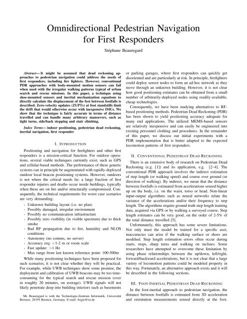
<strong>Omnidirectional</strong> <strong>Pedestrian</strong> <strong>Navigation</strong><strong>for</strong> <strong>First</strong> <strong>Responders</strong>Stéphane BeauregardAbstract— It might be assumed that dead reckoning approachesto pedestrian navigation could address the needs offirst responders, including fire fighters. However, conventionalPDR approaches with body-mounted motion sensors can failwhen used with the irregular walking patterns typical of urbansearch and rescue missions. In this paper, a technique usingshoe-mounted sensors and inertial mechanization equations todirectly calculate the displacement of the feet between footfalls isdescribed. Zero-velocity updates (ZUPTs) at foot standstills limitthe drift that would otherwise occur with inexpensive IMUs. Weshow that the technique is fairly accurate in terms of distancetravelled and can handle many arbitrary manoevers, such astight turns, side/back stepping and stair climbing.Index Terms— indoor positioning, pedestrian dead reckoning,inertial navigation, first responderI. INTRODUCTIONPositioning and navigation <strong>for</strong> firefighters and other firstresponders is a mission-critical function. For outdoor operations,several viable techniques currently exist, such as GPSand cellular-based methods. The per<strong>for</strong>mance of these genericsystems can in principle be augmentated with rapidly-deployedoutdoor local beacon positioning systems. However, outdoorsis not where the critical needs lie: a large fraction of firstresponder injuries and deaths occur inside buildings, typicallywhen these are on fire and/or structurally compromised. Consequently,the technical requirements <strong>for</strong> worst case scenariosare very demanding:- Unknown building layout (i.e. no plan)- Possibly damaged, irregular environment- Possibly no communication infrastructure- Possibly zero visibility (in visible spectrum) due to thicksmoke- Bad RF propagation due to fire, humidity and NLOSconditions- Autonomy (no comms, no server)- Accuracy req: 1 Hz- Max range from last known reference point: 100-500mWhile many positioning techniques have been proposed <strong>for</strong>such scenarios, it is not clear whether they will be practical.For example, while UWB techniques show some promise, thedeployment and calibration of UWB beacons may be too timeconsuming<strong>for</strong> the typical search and rescue mission (overin roughly 20 minutes, on average). UWB signals will notlikely penetrate deep into building interiors such as basementsMr. Beauregard is with the Technologie-Zentrum In<strong>for</strong>matik, UniversitätBremen, 28359 Bremen, Germany. E-mail: bogie@tzi.deor parking garages, where first responders can quickly getdisoriented and are particularly at risk. In principle, firefighterscould deploy sensor nodes to <strong>for</strong>m an ad-hoc network as theymove through an unknown building. However, it is not clearhow good positioning estimates can be obtained from a smallnumber of arbitrarily-deployed nodes using readily-available,cheap technologies.Consequently, we have been studying alternatives to RFbasedpositioning methods. <strong>Pedestrian</strong> Dead Reckoning (PDR)has been shown to yield positioning accuracy adequate <strong>for</strong>many end applications. The utilized MEMS-based sensorsare relatively inexpensive and can easily be engineered intoexisting personnel clothing and procedures. In the remainderof this paper, we discuss our initial experiments with aPDR implementation that is better adapted to the expectedlocomotion patterns of first responders.II. CONVENTIONAL PEDESTRIAN DEAD RECKONINGThere is an extensive body of research on <strong>Pedestrian</strong> DeadReckoning (e.g. [1]) and its application, e.g. [2–4]. Theconventional PDR approach involves the indirect estimationof step length (or walking speed) and course over ground (ordirection of walking). By indirect, we mean that the distancebetween footfalls is estimated from accelerations sensed higherup on the body, i.e. on the waist, torso or head. Non-linearinput-output algorithms such as neural networks relate thevariance of the accelerations and/or their frequency to steplength. The algorithms require ground truth step length trainingdata, acquired via GPS or by walking a surveyed course. Steplength estimates can be very good, on the order of 2-5% ofthe total distance travelled [5].Un<strong>for</strong>tunately, this approach has some severe limitations.Not only must the model be trained <strong>for</strong> a specific user,inaccuracies can arise if the walking surface or shoes aremodified. Step length estimation errors often occur duringstarts, stops, sharp turns and walking on inclines. Someresearchers have attempted to overcome these limitation byusing phase relationships between the up/down, left/right,<strong>for</strong>ward/backward accelerations, but it is not clear that a largevariety of locomotion patterns could be modeled property inthis way. Fortunately, an alternative approach exists and it willbe described in the following sections.III. FOOT-INERTIAL PEDESTRIAN DEAD RECKONINGIn the foot-inertial approach to pedestrian navigation, thedistance between footfalls is estimated from 3D accelerationand orientation measurements sensed directly at the foot.
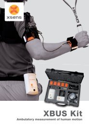
and derived signals were proposed. In our experience, wehave found that that a product of acceleration magnitudeand gyro magnitude works well, but other derived signals allwork similarly well. However, they all suffer from the sameshortcoming: the foot is must be almost completely stationary<strong>for</strong> a fraction of a second. In a future version of this system, adynamic threshold detection algorithm and possibly additionalsensors, such as a pressure or proximity switch, will probablybe required to improve robustness.Fig. 1. An XSens MT motion sensor is held on to the shoe by the laces. Inprinciple, the IMU could be miniaturized and mounted in the heel or insoleof a boot.An inertial measurement unit (IMU), containing tri-axial accelerometers,rate gyros and magnetometers, is solidly attachedto, or mounted in, footwear (Fig. 1). Foot displacementsbetween footfalls are calculated directly by double integratingthe accelerations in the world frame. Our approach is basedto that taken in [6][7][8][9] and elsewhere.A. Inertial MechanizationStandard strap-down mechanization equations were appliedto the IMU measurements. Very briefly, a rotation matrix thatbrings the sensor (or body) coordinate system to the worldcoordinate system is estimated. Then the accelerations in thebody frame are rotated to the world frame with this matrixand the resuling accelerations are double integrated to yield adisplacement in the world frame. See Fig. 2.Initially, we used the rotation matrix calculated directly inour IMU’s internal software. This proved to unsatisfactory asthe orientation estimation algorithm (Kalman/complementaryfilter similar to [10]) must make assumptions about the spectrumof rotation rates. In the case of walking, there are twodistinct sets of dynamics, one very fast <strong>for</strong> the swing phase,and an almost static one <strong>for</strong> the stance phase. We were unableto adjust the tuning parameters of the supplied filter so thatthe orientation results were stable in both phases. Rather thanattempt to write our own very complex quaternion/Kalmansensor fusion filter (as is done [6]), we simply tuned the IMUsoftware to give reliable orientations during the stance phaseand integrated the gyro rotation rate estimates during the swingphase.B. Stance Detection and ZUPTsThe key to the technique are the zero-velocity updates(ZUPTs) that are per<strong>for</strong>med when the foot is at a standstill.These updates must be done correctly and at every stepotherwise the position drifts very quickly due to the relativelylow-per<strong>for</strong>mance sensors in the IMU. We have found thateven a few running strides can wreck havoc on the positionestimation.In principle, a foot standstill is detected when accelerationand gyro sensor readings both drop below experimentallydeterminedthresholds. In [11], thresholds on various rawIV. TOOLSThe main instrument <strong>for</strong> these experiments was the <strong>Xsens</strong>MTi IMU. The sensor was attached to the shoe using the lacesand the data cable run up the pant leg. Data was logged ona carried laptop and post-processed using routines written inMatlab. A uBlox GPS receiver was used to collect groundtruth data <strong>for</strong> experiments per<strong>for</strong>med outdoors.V. RESULTSPrevious experiments such as those described in [9][7][12]were done with “normal” walking, mostly along smoothcourses with shallow turns and relatively constant speeds. In[6], a non-stop, windy path through a two-storey house isfollowed but it is hard to tell from the figure how tight thecorners are. No tests on non-standard walking patterns werereported. <strong>First</strong> responders are unlikely to use a normal styleof locomotion <strong>for</strong> large portions of their missions. With theexception of the very beginning of their mission, they arecontinuously stopping, starting, and turning as they “sweepsearch” floors and rooms.Very tight manoevers that may be more typical of a firstresponder’s locomotion were tested. In Fig. 3(b), circles downto approximately 2m in diameter, or about 4 steps, werereliably tracked by the algorithm. In fact, the PDR trajectoryis more stable than the GPS ground truth in Fig. 3(a). Itseems the GPS receiver’s positioning algorithm was unable tohandle the rapidly turning and crossing track. In Fig. 3(c), sidestepping(from 97m to 77m), diagonal stepping (77m to 60m),and <strong>for</strong>ward/backward criss-cross stepping (60m to 35m) arequalitatively correct, but the scale is off. This may be due to theZUPT threshold settings but further investigation is required.Stair climbing was also tested. Altitude changes <strong>for</strong> eachstep and <strong>for</strong> flights of stairs are easily resolved, see Fig. 4.VI. CONCLUSIONOur preliminary results are encouraging but much furtherwork is required to get a stable, repeatable system. Contrary toprevious experiments with relatively normal walking, our testshave emphasized very tight turning manoevers including onthe-spotturns, side/back stepping and criss-cross walking thatare more typical of a first responder’s locomotion. Stair climbingwas also tested. Not all sensor drifts can be eliminated dueto the low quality of the sensors (especially the gyros) and dueto magnetic perturbations indoors. Future challenging work incomplex sensor fusion algorithms will be required to adressthese issues.
50Accel Values in Sensor Framem/s 20−5040143 144 145 146 147 148 149 150Accel Values in World Frame20m/s 20−20−406143 144 145 146 147 148 149 150Velocity4m/s20−215143 144 145 146 147 148 149 150Position10m50−5143 144 145 146 147 148 149 150Experiment time (seconds)Fig. 2.Dynamics of right foot during start of straight ahead walk.VII. ACKNOWLEDGEMENTSThis research was conducted in the context of theWearIT@Work project (EC IST IP2003 0004216) and underthe direction of Prof. Dr. Otthein Herzog.REFERENCES[1] Q. Ladetto and B. Merminod, “Digital magnetic compass and gyroscopeintegration <strong>for</strong> pedestrian navigation,” in 9th Saint Petersburg InternationalConference on Integrated <strong>Navigation</strong> Systems, Saint Petersburg,Russia, May 27-29 2002.[2] G. Gartner, A. Frank, and G. Retscher, “<strong>Pedestrian</strong> navigation systems inmixed indoor/outdoor environment - the NAVIO project,” in 9th InternationSymposium on Planning & IT (CORP 2004 & Geomultimedia04),February 2004, pp. 165–171.[3] G. Abwerzger, B. Ott, and E. Wasle, “Demonstrating aGPS/EGNOS/Loran-C navigation system in difficult environmentsas part of the ESA project SHADE,” in EURAN 2004 Conference,Munich, Germany, June 2004.[4] J. Rouiller, D. Perrottet, Q. Ladetto, and B. Merminod, “Faciliter ledéplacement des aveugles avec une carte numérique et une interfacevocale,” MPG, pp. 517–521, August 2002.[5] H. Leppakoski, J. Kappi, J. Syrjarinne, and J. Takala, “Error analysis ofstep length estimation in pedestrian dead reckoning,” in ION GPS 2002.Portland, OR: The Institute of <strong>Navigation</strong>, September 24 -27 2002, pp.1136 – 1142.[6] E. Foxlin, “<strong>Pedestrian</strong> tracking with shoe-mounted inertial sensors,”IEEE Computer Graphics and Applications, vol. 25, no. 6, pp. 38–46,2005.[7] L. Ojeda and J. Borenstein, “Non-GPS navigation <strong>for</strong> emergency responders,”in International Joint Topical Meeting: Sharing Solutions <strong>for</strong>Emergencies and Hazardous Environments, Salt Lake City, UT, February12-15 2006.[8] K. F. Stirling, R. and G. Lachapelle, “Evaluation of a new method ofheading estimation <strong>for</strong> pedestrian dead reckoning using shoe mountedsensors,” Journal of <strong>Navigation</strong>, vol. 58, no. 1, pp. 31 – 45, 2005.[9] F. Cavallo, A. Sabatini, and V. Genovese, “A step toward GPS/INSpersonal navigation systems: real-time assessment of gait by foot inertialsensing,” in Proc. IEEE Internat. Conf. Intell. Rob. Syst. (IROS 2005),Edmonton, Canada, August 2005, pp. 1187 – 1191.[10] J. Marins, X. Yun, E. Bachmann, R. McGhee, and M. Zyda, “Anextended kalman filter <strong>for</strong> quaternion-based orientation estimation usingMARG sensors.”[11] R. G. Stirling, “Development of a pedestrian navigation system usingshoe-mounted sensors,” M.Sc. Thesis, Department of Mechanical Engineering,University of Alberta, Calgary, Alberta, Canada, October 2003.[12] R. Stirling, J. Collin, K. Fyfe, and G. Lachapelle, “An innovative shoemountedpedestrian navigation system,” in Proceedings of European<strong>Navigation</strong> Conference GNSS 2003, Graz, Austria, 22 – 25 April 2003.
20Displacement (m)151050Displacement (m)−5Displacement (m)151050 10 20 30 40 50 60 70 80 90 100 110Displacement (m)(a) GPS Ground Truth00 20 40 60 80 100Displacement (m)105,0(b) Turn Tests0,020 30 40 50 60 70 80 90 100 110Displacement (m)(c) Side/Backwards TestsFig. 3. Outdoor test results: The GPS ground truth plot (a) includes an outer perimeter segment of normal walking. This portion was correctly estimated bythe algorithm and the results are not shown here. In (b) and (c), the points on the track represent individual footfalls as detected by the algorithm.Vertical displacement (m)64200 5 10 15 20 25 30 35 40 45 50Horizontal displacement (m)Fig. 4. Stair climbing: Six flights of stairs while climbing three floors are easily resolved. It is also possible to resolve the vertical motion of individual stepsin some cases.