K275 WEB NOTES.cdr - Oatley Electronics
K275 WEB NOTES.cdr - Oatley Electronics
K275 WEB NOTES.cdr - Oatley Electronics
- No tags were found...

Create successful ePaper yourself
Turn your PDF publications into a flip-book with our unique Google optimized e-Paper software.
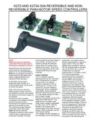
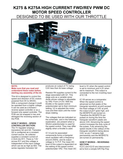
<strong>K275</strong> & <strong>K275</strong>A HIGH CURRENT FWD/REV PWM DCMOTOR SPEED CONTROLLERDESIGNED TO BE USED WITH OUR THROTTLENOTE:Make sure that you read andunderstand these notes beforestarting any assembly of the kit.This kit is designed to control thespeed and direction of DC motorspowered from 9V to 48VDC.With a component change it couldbe operated from a higher voltage.It can be used as a forward /reverse speed controller or as aforward only speed controller. ThePCB can be snapped in two anddisregard the reversing section ofthe PCB.HOW IT WORKS – SPEEDCONTROLLER SECTION:The 7V regulator employstransistors Q2 and Q3. TransistorQ2 is configured as a constantcurrent source. Its collectorsupplies a constant current of2.3mA into R11: There is 7.6Vacross R11 and this voltage isindependent of the input voltagewhich can be as high as 60V. Theseries regulator transistor Q2produces an output of 7V, being0.6V less than its base voltage.Resistor R4 supplies current to thestage associated with Q1. Thisstage acts as a variable zenerdiode whose voltage is adjustableby VR2: From 2-4.4V. With thethrottle or the speed controlpotentiometer set to their minimumsetting, V2 is adjusted the motorruns and then back until the motorstops rotating.The voltages that are indicated onthe schematic, and in the followingexplanation, are present when a5Kohm potentiometer is used forthe speed control. They may differslightly when a throttle is used.IC1:A and its associatedcomponents forms a triangularwave oscillator with a frequencyaround 250Hz, and its outputvoltage is 1V P-P. The mean DClevel of this output is dependent onthe setting of the speed controlpotentiometer VR2. This mean DClevel is 3V when the speed controlis set to minimum and 4.2V whenset to maximum. This output isconnected to the non inverting inputof IC1:B.IC1:B serves as a comparator.When the speed control isadvanced so that peaks of thetriangular waveform at pin5 exceedthe fixed voltage of 3,6V at pin6,the output at pin7 goes high, andthe MOSFETS are turned on.Therefore the MOSFETS arepulsed on during the time thetriangular waveform peaks areabove 3.6V. Advancing the speedcontrol increases the duty cycle ofthe pulses. Fully advancing thespeed results in the valleys of thetriangular waveform being above3.6V, so pin 7 remains highpermanently and the MOSFETSare turned on permanently.HOW IT WORKS – REVERSINGSECTION:IC2:C and IC2:D are interconnectedto form a simple S/R Flip-Flop
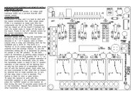
which is toggled by active lowlevels on pins 8 and 13. When thereversing switch is not connectedpins 1 and 2 of IC2:A, which isconfigured as an inverter, is pulledhigh by the series combination ofresistors R19 and R21, therefore itsoutput pin3 is low. The Flip-Flopoutput pins11 and 13 are high andlow respectively: Led L2 lights toindicate that the controller is in theForward direction, and the relayswitching transistor Q4 is off.Therefore when power is firstapplied.The reverse button will not changethe direction of the controller untilthe controller has stopped for ashort time. This feature is to helpavoid sudden changes in direction.Its duration is controlled by C6. The100uF C6 gives a delay of around 4seconds. To shorten the delayreduce the value of C6.For the following explanationassume that diodes d are removedfrom the circuit. When the motor isrunning the drains of MOSFETS(M1 & M2) are pulse / pulled low.capacitor C6 is quickly charged viathe isolating diode D3 and R18 thusproducing a low at pins 5 & 6, theoutput of inverter IC is at a high anddiodes D5 and D4 are forwardbiased and bias both the inputs tothe gates at a high so the flip flopcan not toggle. There for the motorcan not change direction whilstthere is power being applied to themotor.SOFT START FEATUREThis feature is to help avoid suddendestructive or dangerous starts. Itsduration is controlled by the electrolyticcapacitor C3. To shorten theduration reduce the value of C3.The soft start can be removed byremoving C3 from the circuit.For High current use the majortracks on the PCB can be built upwith additional solder to thicken thetracks.The transistor Q2 in regulator partof the circuit may require a smallheatsink for 36/48V operation.The reversing button can bereplaced with a remote button ortoggle switch.If you wish to use this kit as a highpower forward direction only speedcontroller snap the PCB in two anddisregard the relay section of thePCB.THROTTLE / POTENTIOMETERIf an external throttle or potentiometerVR1(The "SPEED" trim-pot)should be omitted.A 5K external pot can be used tocontrol the speed. A pot will wearand eventually become unreliable.For applications where the speedwill be constantly vary a throttle isbest as this uses an internalmagnet and Hall effect sensor.HIGH CURRENT RELAYSThe relays supplied in this kit areconnected in parallel and are ratedto switch 30A each. They canhandle a lot more than the ratedcurrent once the contacts haveclosed. For this and also for safetyreasons a change of direction canonly be effected once the controllerhas stopped for a short time.CONNECTIONSThe connections from the battery tothe <strong>K275</strong> must be heavy duty. Ifthere is too much voltage drop thecontroller will not work correctly andmay fail as a result.PARTS LISTRESISTORS2 22R 1/4W1 470R 1/4W1 560R 1/4W2 1K 1/4W3 2K7 1/4W1 3K3 1/4W3 4K7 1/4W3 39K 1/4W2 47K 1/4W1 220K 1/4W5 1M 1/4W1 2K POTENTIOMETER1 5K POTENTIOMETERCAPACITORS1 4n7 GREENCAP2 47n GREENCAP1 0.1uF MONOLYTHIC CAP4 100uF/16V1 100uF/63VSEMI-CONDUCTORS4 4148 SIGNAL DIODE1 IN4004 POWER DIODE1 SR1060 SHOTKY DIODE1 C8050 TRANSISTOR1 LM358 OP-AMP + SKT1 4093 CMOS IC + SKT2 IRF1060 MOSFET1 BDX37 TRANSISTOR1 BD140 TRANSISTOR1 BD681 TRANSISTOR3 3mm RED LEDMISC.1 PCB LABELED <strong>K275</strong>1 TACTILE PUSH-BUTTON2 2 WAY SCREW TERMINAL4 12V/30A RELAY6 M3 X 10MM SCREWS6 M3 HEX NUTS6 3mm X 7mm WASHERSA small error was made in theproduction of the PCBs for thiskit. To fix the problem a wire linkis required under the PCBbetween the points shown .OPERATING VOLTAGE RANGEDiagrams for setting the voltage areprovided in these notes with theschematic diagram. By linking thepoints labeled on the PCB that areindicated in the diagram this kit canbe operated from 12, 24 and 36VDC. If you wish to use 36V you willneed to provide a 120 Ohm resistor(2W or greater). We do not stock orsupply this component.ASSEMBLY OPTIONSFORWARD ONLY
SCHEMATIC AVAILABLE WITH THE PURCHASE OF A KIT
SCHEMATIC AVAILABLE WITH THE PURCHASE OF A KIT
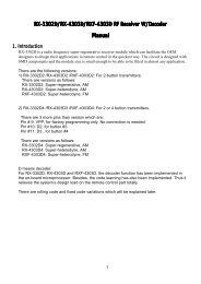
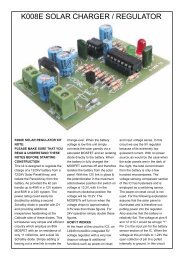
REMOTEREVERSETOGGLESWITCHOR PUSH-BUTTONMOTORBATTERY/SHANDLEBARTHROTTLEORPOTENTIOMETER(SEE TEXT)