NOTE - Oatley Electronics
NOTE - Oatley Electronics
NOTE - Oatley Electronics
- No tags were found...

You also want an ePaper? Increase the reach of your titles
YUMPU automatically turns print PDFs into web optimized ePapers that Google loves.
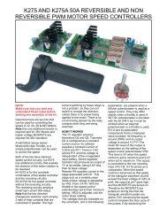
<strong>NOTE</strong>Make sure that you read these notes from start to finish beforeatempting any construction of any of the kits.These notes may contain last minute warnings and/or changes.CAUTIONWhen connected to any machine unexpected movements that maybe dangerous may occur. To minimise this possibility always turnoff your CNC equipment while your computer is booting or notdirectly involved with controlling your CNC equipment.INTRODUCTION TO OUR CNC KITSThis series of kits K142A, K142B, K142C and K142D are designed tocontrol machinery via a computer using up to 4 stepper motors.This system can be used to manufacture one or many items extremelyaccurately & can be retro fitted to existing milling machines or lathes etc.BASIC PROCEDUREDepending on the software chosen, usually an item is drawn, thedrawing file is then converted to a Gcode file. The Gcode is then read byyour CNC software that in turn controls your machine.Gcode can also be written with a text editor like Notepad etc.APPLICATIONSSome common applications include: milling, turning, engraving, drilling,hot wire foam cutting and animation camera control.SOFTWAREYou will have to consider to best software for your application. Some ofthe software available include KCAM, STEPSTER, DANCAD and EMC(Enhanced Machine Controller). Some is freeware, some shareware andsome is commercial.Note:There are many different types of software that are available, for thatreason it is impossible for <strong>Oatley</strong> <strong>Electronics</strong> to advise on how to useyour software. To use this kit your software should be the STEP &DIRECTION type (this is the most common type). Most software alsohas configure-able pin connections to match the connections required bythe our kits.drawn by the motor and it's power output slowly drop until it reaches acertain speed (this point varies greatly with motor type) then suddenlythe current and power drop to almost nothing, making the motor almostuseless at anything other than low speeds. This is caused byinsufficient time for each coil's field to break down before the next step.Different systems are often employed to increase the speed of steppermotors like ballast resistors or chopper drives.BALLAST RESISTORSTo help overcome the lack of performance high wattage resistors areconnected in series with the motor coils and a power supply higherthan the motor's rated voltage is used.CHOPPER DRIVESChopper drives or PWM (pulse width modulated) drives turn on and off(at high speed ) a power supply higher than the motor's rated voltage.This technique is a linear response to a non-linear problem.CONSTANT CURRENT DRIVESThis type of drive maintains motor current and power by incensing thevoltage to the motor as the motor speed rises. Constant current drivesforce each coil's field to collapse quicker allowing the motor to run muchfaster.Our new (K142C) Constant Current Source systems sense the drop incurrent and increase the voltage to the motor and thus the current andpower is maintained with higher speeds.A common motor we tested gave similar torque at around 300 RPM asat 1 or 2 RPM (this is as FAST as we tested with a 200 step motor).Because of the wide voltage output range of the constant currentsource we had to re-design our (K142) CNC Stepper Motor Driver Kit tocope.There are a number of cheep ripoff copies of our K142B kit but mostdon't allow for the wide voltage range produced by ballast resistor,chopper or constant current system drives.DRIVING STEPPER MOTORSThe major problem is as a stepper motor's speed increases the current
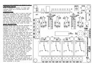
BASIC KIT DESCRIPTIONK142A is a PC interface that helps to simplify wiring, it also provides 2relays that are controlled by your PC and can be used to switch justabout anything.CONNECTIONSMost of the software available uses or can be configured to use thesame connections of the printer port. K142A uses the followingconnections.ZCPC Pin Function2 X axis stepXY3 X axis direction4 Y axis step5 Y axis direction6 Z axis stepThe "Y" axis is usually a "back andforth" movement, The "X" is usually7 Z axis direction "left and right" movement and the "C"8 C axis stepaxis is usually a rotary axis around9 C axis direction the "Z" axis but it can also be used18-25 GNDas a fourth axis in a foam wing cutter.The other pins not shown here are often used for limit and homeswitches and will vary depending on the software you choose to use.In some cases they may not be needed at all or they can be disabled.The power supply in connection is required for the relays and 12VDCoutput. We recommend 9VAC or 12VDC from a power adaptor or othersimilar supply. The power supply 12VDC output is used to supply thelogic (ICs etc.) of each of the K142B or K142D kits.The axis outputs supply step and direction signals to each of the K142Bor K142D kits. The AUX I/O terminals can generally be connected tothings like switches etc. that are placed at the limits of the movement ofyour CNC machine. This is to stop you machine from moving too far.These connections will vary depending on the software you use, checkthe documentation that comes with your software..CAUTION:Although the relays used in this kit are mains rated we do notrecommend that they be connected to mains power as it may bedangerous and result in electric shock.The relays can be used to switch on or off auxiliary items such as yourmachine's spindle motor, coolant, hot wire, drill, dust extractor or vacuumcleaner, just about anything you can think off. Relay1 is controlled bypin17 and Relay2 is controlled by pin16 of your PC.12VDC output. The power supply 12VDC output is used to supply thelogic (ICs etc.) of each of the K142B kits. We recommend 9VAC or12VDC from a power adaptor or other similar supply and should havethese in stock for less than $10.The axis outputs supply step and direction signals to each of theK142B or K142D kits. The AUX I/O terminals can generally beconnected to things like switches etc. that are placed at the limits of themovement of your CNC machine. This is to stop you machine frommoving too far, in some cases may not be needed at all. Theseconnections will vary depending on the software you use, check thedocumentation that comes with your software.AUX. I/OStep anddirectionsignalsfor eachaxis.Powersupply12V outPowersupplyinputAUX. I/ORelay 1Relay 2The power supply IN connection is required to power the relays and
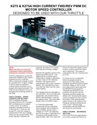
K142B BASIC KIT DESCRIPTIONK142B is a stepper motor controller that interprets the step and directionsignals from the PC into the output sequences required by the steppermotors.MOTOR CONNECTIONSTo find your correct motor connections measure the resistance of themotor coil wires. If when running your motor vibrates instead of rotatingswap connection "A" with "B" or "C" with "D".0 ohmsFrom just afew ohms toover 100 ohmsAMOTORCFrom just afew ohms toover 100 ohmsBDHEATSINKINGIf heatsinking is required and only one heatsink is used for all MOSFETSinsulation will need to be fitted to each of the MOSFETS. If four separateheat sinks are used (one heatsink fitted between each back to back pair)no insulation is required.0 ohms
K142D BASIC KIT DESCRIPTIONK142D is a stepper motor controller that interprets the step and directionsignals from the PC into the output sequences required by the steppermotors.MOTOR CONNECTIONSTo find your correct motor connections measure the resistance of themotor coil wires. If when running your motor vibrates instead of rotatingswap connection "A" with "B" or "C" with "D".6 WIRE MOTOR DIAGRAM0 ohmsCCTAMOTOR<strong>NOTE</strong>:The MOSFETs supplied with this kit are suitable for a maximum supplyvoltage of 60VDC. If you wish to use the maximum recommended supplyvoltage for the K142 system you will need to change the MOSFETs toIRFZ44Z (TO220 type) or simalar, (see out website for pricing etc.). Youwill require either 4 or 8 depending on the current drawn by your motors.HEATSINKINGIf you use TO220 type MOSFETS you can use additional heatsinking.If heatsinking is required and only one heatsink is used for all MOSFETSinsulation will need to be fitted to each of the MOSFETS. If four separateheat sinks are used (one heatsink fitted between each back to back pair)no insulation is required.ASSEMBLYAssembly is relatively simple, even the (Surface Mount Devices) SMDMOSFETs are easy to fit. Start by holding a MOSFET in place with awashing peg or similar, then solder the 2 legs of the MOSFET. Nextsolder the back of the MOSFET to the PCB, this must be done as itforms one of the connections required as well as providing heatsinking.Y ohmsX ohmsCTX ohmsBTo confirm motor connectionsuse a multi-meter and measurethe resistance of the coils.Y ohms = 2 * X ohms8 WIRE MOTOR DIAGRAMD0 ohmsMOTOR
8-60VDC
K142C BASIC KIT DESCRIPTIONK142C is a constant current power supply that is used to supply thecorrect current to the stepper motors to maintain higher performance.This kit is recommended for use with a 15-34V power supply and lowvoltage motors. The ideal situation would be a 33-34V supply with 2-4Vmotors. The K142C is adjustable to suit motors from around 0.5A to2.5A. By changing the values of R6 and/or R7 lower and higher rangescan be achieved. See construction notes for details.CONSTRUCTIONFit the transistors and the regulators to the PCB as shown but do notsolder them in place. Remove the insulating pad from the heatsink, cutit in half and punch a hole in one end of each piece as shown. Theseinsulators are used between the LM317 regulators and the heatsink butare not required for the transistors. Remove the regulators andtransistors from the PCB and attached them to the heatsink, Make sureto fit the insulating washer to the screw that holds IC1, do not tightenthe screws. Now fit the heatsinkand it's components to the PCB. Makesure that the components are flat against the circuit board and solderthem in to the PCB. Now tighten the screws.To change the current adjustment range select a new resistance for R6and R7 using the calculation bellow. Remember that this will set theminimum current, you should select a minimum current below what isrequired so to allow for adjustment above and below the requiredcurrent.1.25 / Amps out = Ohms1.25 divided by the required minimum current = resistance in ohmsYou may need to place resistors in parallel or series to obtain the resistanceneeded as shown in the next image. Note that the top connections of R6and R7 are connected together for series connection.
To set the current apply your power supply to the input terminals of thek142C, connect an amp meter or multi-meter to the output terminalsand adjust VR1 to set the desired current.PARALLEL CONNECTIONSERIES CONNECTION<strong>NOTE</strong>:Some circuit boards may have incorrect output labeling.The correct terminal connections are as shown in the component layoutimage on the next page .
<strong>NOTE</strong>:Some circuit boards may have incorrect output labeling.The correct terminal connections are as shown here.
Wiring diagram for afull 3 axis systemusing K142B kitsfor 4 wire motorsSTEPPER MOTORPOWER SUPPLYTo PC parallel(printer) portTo "C" or fourth axisstep & direction if used.See I/OnotesSee I/OnotesSee I/OnotesStep & directionconnections foreach axis.12VDCOUT9VAC or12VDC"Z" axis stepper motor"Y" axis stepper motor"X" axis stepper motor
Wiring diagram for afull 3 axis systemusing K142D kitsfor 6 AND 8 wirestepper motorsSTEPPER MOTORPOWER SUPPLYTo PC parallel(printer) portTo "C" or fourth axisstep & direction if used.See I/OnotesSee I/OnotesSee I/OnotesStep & directionconnections foreach axis.12VDCOUT9VAC or12VDC"Z" axis stepper motor"Y" axis stepper motor"X" axis stepper motor
<strong>NOTE</strong>!Due to an error in the design of this circuit board a smalltrack was omitted. This track should have been betweenthe large pad behind each MOSFETs and the track thatpasses between the legs of each MOSFET. The metaltag of each MOSFET is also connected to the stump ofthe middle leg of each MOSFET. To fix this error simplysolder a short wire link as shown in the diagram.SOLDERLINKHERE