
Create successful ePaper yourself
Turn your PDF publications into a flip-book with our unique Google optimized e-Paper software.
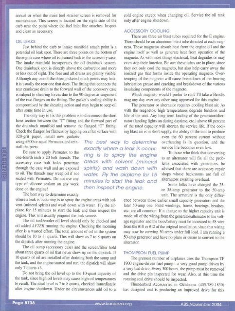
annual or when the main fuel strai ner screen is removed formaintenance. This screen is located on the right side of thecarb near the point where the fuel inlet line attaches. Inspectand clean as necessary.OIL LEAKSJust behind the carb to intake manifold attach point is apotential oi l leak spot. There are three points on the bottom ofthe engine case where oil is drained back to the accessory case.The intake manifold incorporates the oil drainback system.One drainback spot is directly above the carburetor and moreor less out of sight. The fore and aft drains are plainly visible.Although anyone of the three gasketed attach points may leak,it is usually the rear one that does. The fitting that con nects therear crankcase drain to the forward wall of the accessory caseis subject to shearing forces due to the 90-degree arrangementof the two flanges on the fitting. The gasket's sealing ability iscompromised by the shearing action and may begin to seep oilafter some time in use,The only way to fi x this problem is to disconnect the shanhose section between the 'T ' fi tti ng and the fo rward palt ofthe drainback mani fold and remove the flanged "T" fitting.Check the flanges for flatness by lapping on a flat surface with320-grit paper, install new gasketsusing #300 or equal Permatex and reinstallthe parts.Be sure to apply Permatex to theone-fourth inch x 20 bolt threads. Theaccessory case bolt holes penetratethrough the case wall and are exposedto oil. The threads may weep oil if notsealed with Permatex. Do not use anytype of silicone sealant on any workdone on the engine!The best way to determineexactly where a leak is occurringis to spray the engineareas with solvent (mineralspirits) and wash down withwater. Fly the airplane for ) 5minutes to start the leak andthen inspect the engine.The best way to detennine exactlywhere a leak is OCCUlTing is to sp ray the engine areas with sol vent (mineral spirits) and wash down with water. Fly the airplanefo r 15 minutes to start the leak and then inspect theengine. This will usually pinpoint the leak source.The oil tank/cooler oil level should only be checked andoil added AFTER running the engine. Checking the morningafter is a wasted effon. The total amount of oi l in the systemshould be 10 to II quarts. This will show as 7 to 8 quarts onthe dipstick after running the engine.The oil sump (accessory case) and the screen/fi lter holdabout three qUilltS of oil that never show up on the dipstick. If10 quarts of oil are insta lled after draining both the sump andthe tank, and the engine started and run, the dipstick will showonly 7 qums +/-.Do not bring the oi l level up to the IO-quart capacity ofthe tank. since high oil levels may cause high oi l temperaturesto result. The ideal level is 7 to 8 quarts, checked immediatelyafter engine shutdown. Under no circumstances add oil to acold engine except when changing oil. Service the oil tankonly after engine shutdown.ACCESSORY COOLINGThere are three air blast tubes required for the E engine.There should be an aluminum blast tube directed at each magneto.These magnetos absorb heat from the engine oil and theengine itself as well as generate heat from operation of themagneto. As with most things electrical, heat degrades or mayeven stop their function. Be sure these tubes ill'e in place, sincethey not only cool the magneto, but also help carry away theionized gas that forms inside the operating magneto. Overtempingof the magneto will cause breakdown of Lhe bearinglubrication grease and cracking and breakdown of the variousinsulating components of the magneto.Which magneto would I prefer to run? I'll take a Bendixmag any day over any other mag approved for thi s engine.The generator or alternator requires cooling blast air. Aswith the magnetos, high temperatures degrade func tion andlife of the unit. Any long-term loading of the generator/alternator(landing lights on during daytime, etc.) abo ve 60 percentof the rated capacity will shorten the service life. If the coolingblast air is in shan supply, the abi lity of the unit to produceeven the 60 percent current withoutoverheating is in question. and theserv ice life becomes even less.To those who think that conveI1ingto an alternator will fix all the problemsassociated with generators. beadvised that there are accessory repairshops whose backrooms are full ofalternators awaiting overhaul.Some fo lks have changed the 25-or 35-amp generator to the 50-ampunit. The armature is the only differencebetween those earl ier small capacity generators and thelater 50-amp one. Field windings, frame, bearings, brushes,etc. are all common. If a change to the higher capacity unit ismade, all of the wiring from the generator/alternator to the voltageregulator and the buss/battery must be increased to #8 wirefrom the #10 or #12 of the original installation, since that wiringmay now be carrying 50 amps under full load. I am running a50-amp generator and have no plans or desire to conven to thealternator.THOMPSON FUEL PUMPThe greatest number of airplanes uses the Thompson TF1900 engine-d ri ven fuel pump- a very good pump driven bya very bad drive. Every 300 hours. the pump must be removedand the drive pin inspected for wear. Also, at this time therotating seal drive should be inspected.Thunderbird Accessories in Oklahoma (405-789-1 830)has designed and is producing an improved dri ve for thi s