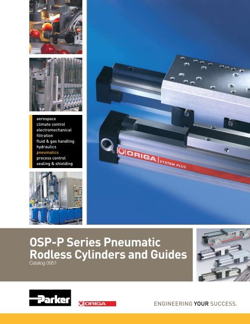
OSP-P Series Pneumatic Rodless Cylinders and ... - Parker ORIGA
OSP-P Series Pneumatic Rodless Cylinders and ... - Parker ORIGA
OSP-P Series Pneumatic Rodless Cylinders and ... - Parker ORIGA

You also want an ePaper? Increase the reach of your titles
YUMPU automatically turns print PDFs into web optimized ePapers that Google loves.
Catalog 0951Conversion Table<strong>OSP</strong>-P <strong>Pneumatic</strong> <strong>Rodless</strong> <strong>Cylinders</strong> <strong>and</strong> GuidesELECTRIC ACTUATOR2D & 3DCAD Drawingscan be downloadedfrom websitewww.parkeroriga.comAttention!Contact PARKER-<strong>ORIGA</strong> for sizing software<strong>and</strong>/or technical assistance630-871-8300Application Sheet on Page 104All dimensions are in European-St<strong>and</strong>ard.Please convert all in US-St<strong>and</strong>ard.Conversion TableMultiply By to ObtainMillimeters .03937 InchesNewtons .2248 Lbs.(F)Newton-Meters 8.8512 In-LbsKilograms 2.205 Lbs.Inches 25.4 MillimetersLbs.(F) 4.448 NewtonsIn-Lbs .113 Newtons-MetersLbs. .45359 Kilograms<strong>ORIGA</strong>i<strong>Parker</strong> Hannifin Corporation<strong>Parker</strong>-OrigaGlendale Heights, Illinoiswww.parkeroriga.com
Catalog 0951Notes<strong>OSP</strong>-P <strong>Pneumatic</strong> <strong>Rodless</strong> <strong>Cylinders</strong> <strong>and</strong> GuidesPARKER-<strong>ORIGA</strong> rodless pneumatic cylindersare the first rodless cylindersthat have been approved for use inpotentially explosive atmospheres inEquipment Group II, Category 2 GDThe <strong>Cylinders</strong> are to the ATEX Certification94/9/EG (ATEX 95) for <strong>Pneumatic</strong>Components.For the different classifications <strong>and</strong> detailsplease see pages 27 <strong>and</strong> 92.<strong>ORIGA</strong>for use in Ex-Areas+120°CHigh Temperature Versionfor temperatures up to +120°Cfor Clean Room Applicationscertified toDIN EN ISO 14644-1-40°CLow Temperature Versionfor temperatures up to-40°CStainless steel versionfor special applications0.005 m/sSlow Speed Versionv = 0.005 – 0.2 m/swith special pneumaticcushioning system for cycletime optimization,for Ø 16 to 50 mm– on request< 30 m/sHigh Speed Versionvmax. = 30 m/s<strong>ORIGA</strong>ii<strong>Parker</strong> Hannifin Corporation<strong>Parker</strong>-OrigaGlendale Heights, Illinoiswww.parkeroriga.com
Catalog 0951Index<strong>OSP</strong>-P <strong>Pneumatic</strong> <strong>Rodless</strong> <strong>Cylinders</strong> <strong>and</strong> GuidesContents – Linear DrivesnewnewnewnewPageIntroduction – <strong>OSP</strong> Concept 1-3Modular Components Overview 4-5Control Examples for <strong>OSP</strong>-P 6<strong>OSP</strong>-P Application examples 7<strong>Rodless</strong> <strong>Pneumatic</strong> <strong>Cylinders</strong>Overview 9-13<strong>Series</strong> <strong>OSP</strong>-P ø10 to 80 mm 15-21Integrated Valves VOE 22-23Clean Room <strong>Cylinders</strong> 24-26ATEX-Version 27ATEX-Version Plain Bearing 27Guide SLIDELINEBi-parting Version 28-29Linear GuidesOverview 31-32Plain Bearing Guide SLIDELINE 33-34Roller Guide 35-38POWERSLIDEAluminium-Roller Guide 39-40PROLINEAluminium-Roller Guide 39-40– PROLINE with ACTIVE-BrakeRecirculating Ball Bearing Guide 41-43STARLINE– Variable Stop VS 44-46Heavy Duty Guide HD 47-49– Variable Stop VS 50BrakesOverview 51-52Page<strong>OSP</strong> – AccessoriesOverview 65-66Clevis Mounting 67-68End Cap Mounting 69Mid-Section Support 70Mountings for Linear Drives fitted 71-77with <strong>OSP</strong>-GuidesInversion Mounting 78Adaptor Profile 79T-Slot Profile 80Connection Profile 81Duplex Connection 82Multiplex Connection 83Magnetic Switches– St<strong>and</strong>ard Version 84-86new – T-Slot Version 88-91new – ATEX-Version 92-94Wireway Cover 87– Metric Conversion Fittings 87newDisplacement Measuring Systems<strong>ORIGA</strong> SENSOFLEXOverview 95-96– <strong>Series</strong> SFI-plus 97-99Service Packs 100Ordering Instructions 102-103Application Sheet 104Safety Guide 105-106Offer of Sale 107ACTIVE-BrakesACTIVE-Brake 53-56– for St<strong>and</strong>ard CylinderPlain Bearing Guide SLIDELINE 33-34– with ACTIVE-BrakeAluminium-Roller Guide 39-40PROLINE with ACTIVE-BrakePASSIVE-BrakesMulti-Brake: PASSIVE-Brake with 57-60Plain Bearing Guide SLIDELINEMulti-Brake: PASSIVE-Brake with 61-63Aluminium-Roller Guide PROLINE<strong>ORIGA</strong>1 <strong>Parker</strong> Hannifin Corporation<strong>Parker</strong>-OrigaGlendale Heights, Illinoiswww.parkeroriga.com
Catalog 0951The System Concept<strong>OSP</strong>-P <strong>Pneumatic</strong> <strong>Rodless</strong> <strong>Cylinders</strong> <strong>and</strong> GuidesOne Concept – Three Drive OptionsBased on the <strong>ORIGA</strong> rodless cylinder, proven in world wide markets, PARKER-<strong>ORIGA</strong> now offers the complete solution forlinear drive systems. Designed for absolute reliability, high performance, ease of use <strong>and</strong> optimized engineering the <strong>ORIGA</strong>SYSTEM PLUS satisfies even the most dem<strong>and</strong>ing applications.<strong>ORIGA</strong> SYSTEM PLUSis a totally modular concept whichoffers the choice of pneumatic orelectric actuation, with guidance <strong>and</strong>control modules to suit the exactneeds of individual installations.The actuators at the core of thesystem all have a common aluminiumextruded profile, with double dovetailmounting rails on three sides, theseare the principle building blocks of thesystem to which all modular optionsare directly attached.SYSTEM MODULARITY• <strong>Pneumatic</strong> Drive– For all round versatility<strong>and</strong> convenience,combining ease of control<strong>and</strong> broad performancecapability. Ideally suited forpoint-to point operations,reciprocating movements<strong>and</strong> simple traverse /transfer applications.• Electric Screw Drive– For high force capability<strong>and</strong> accurate path <strong>and</strong>position control.• Electric Belt Drive– For high speed appli cations,accurate path <strong>and</strong> position control<strong>and</strong> longer strokes.For additional information on electriclinear actuators, please contactfactory for <strong>OSP</strong>-E literature.• Different guidance options providethe necessary level of precision,performance <strong>and</strong> duty for variousapplications.• Compact solutions, which aresimple to install <strong>and</strong> can be easilyretrofitted.• Valves <strong>and</strong> control options can bedirectly mounted to the actuatorsystem.• Diverse mounting options to providetotal installation flexibility.<strong>ORIGA</strong>2 <strong>Parker</strong> Hannifin Corporation<strong>Parker</strong>-OrigaGlendale Heights, Illinoiswww.parkeroriga.com
Catalog 0951The System Concept<strong>OSP</strong>-P <strong>Pneumatic</strong> <strong>Rodless</strong> <strong>Cylinders</strong> <strong>and</strong> GuidesOne Concept – Three Drive Options* For information on Electric Linear Drives, contact factory for literatureBasic Linear DriveSt<strong>and</strong>ard VersionDuplex Connection● <strong>Series</strong> <strong>OSP</strong>-P● <strong>Series</strong> <strong>OSP</strong>-P● <strong>Series</strong> <strong>OSP</strong>-E*Belt driveBelt drive with integrated GuidesVertical belt drive with recirculatingball bearing guide● <strong>Series</strong> <strong>OSP</strong>-E*Screw drive (Ball Screw, Trapezoidal Screw)Air Connection on theEnd-face or both at One End● <strong>Series</strong> <strong>OSP</strong>-PClean Room Cylindercertified toDIN EN ISO 146644-1● <strong>Series</strong> <strong>OSP</strong>-P● <strong>Series</strong> <strong>OSP</strong>-E..SBProducts forATEX Areas● <strong>Series</strong> <strong>OSP</strong>-P<strong>Rodless</strong> <strong>Cylinders</strong>Products forATEX Areas● <strong>Series</strong> <strong>OSP</strong>-P<strong>Rodless</strong> <strong>Cylinders</strong>with Linear Guide SLIDELINEBi-parting Version● <strong>Series</strong> <strong>OSP</strong>-PMultiplex Connection● <strong>Series</strong> <strong>OSP</strong>-PLinear Guides– SLIDELINE● <strong>Series</strong> <strong>OSP</strong>-P● <strong>Series</strong> <strong>OSP</strong>-E Screw drive*Linear Guides– POWERSLIDE● <strong>Series</strong> <strong>OSP</strong>-P● <strong>Series</strong> <strong>OSP</strong>-E Belt drive*● <strong>Series</strong> <strong>OSP</strong>-E Screw drive*Linear Guides– PROLINE● <strong>Series</strong> <strong>OSP</strong>-P● <strong>Series</strong> <strong>OSP</strong>-E Belt drive*● <strong>Series</strong> <strong>OSP</strong>-E Screw drive*Linear Guides– STARLINE● <strong>Series</strong> <strong>OSP</strong>-PHeavy Duty Linear Guides– HD● <strong>Series</strong> <strong>OSP</strong>-P● <strong>Series</strong> <strong>OSP</strong>-E Screw drive*Brakes● Active BrakesIntegrated3/2 Way Valves● <strong>Series</strong> <strong>OSP</strong>-P● Passive BrakesClevis Mounting● <strong>Series</strong> <strong>OSP</strong>-P● <strong>Series</strong> <strong>OSP</strong>-E Belt drive*● <strong>Series</strong> <strong>OSP</strong>-E Screw drive*End Cap Mounting● <strong>Series</strong> <strong>OSP</strong>-P● <strong>Series</strong> <strong>OSP</strong>-E Belt drive*● <strong>Series</strong> <strong>OSP</strong>-E Screw drive*Mid-Section Support● <strong>Series</strong> <strong>OSP</strong>-P● <strong>Series</strong> <strong>OSP</strong>-E Belt drive*● <strong>Series</strong> <strong>OSP</strong>-E Screw drive*Magnetic Switches● <strong>Series</strong> <strong>OSP</strong>-P● <strong>Series</strong> <strong>OSP</strong>-E Belt drive*● <strong>Series</strong> <strong>OSP</strong>-E Screw drive*SENSOFLEX-Measuring System● <strong>Series</strong> SFI-plusVariable Stop VS● <strong>Series</strong> <strong>OSP</strong>-Pwith Linear Guide STL, HDInversion Mounting● <strong>Series</strong> <strong>OSP</strong>-P● <strong>Series</strong> <strong>OSP</strong>-E Belt drive*● <strong>Series</strong> <strong>OSP</strong>-E Screw drive*<strong>ORIGA</strong>3 <strong>Parker</strong> Hannifin Corporation<strong>Parker</strong>-OrigaGlendale Heights, Illinoiswww.parkeroriga.com
Catalog 0951Modular Components Overview<strong>OSP</strong>-P <strong>Pneumatic</strong> <strong>Rodless</strong> <strong>Cylinders</strong> <strong>and</strong> Guides<strong>Rodless</strong> <strong>Cylinders</strong> <strong>Series</strong> <strong>OSP</strong>-PLinear Drives <strong>OSP</strong>-P10 <strong>OSP</strong>-P16 <strong>OSP</strong>-P25 <strong>OSP</strong>-P32 <strong>OSP</strong>-P40 <strong>OSP</strong>-P50 <strong>OSP</strong>-P63 <strong>OSP</strong>-P80Theoretical force at 6bar [N] 47 120 295 483 754 1178 1870 3010Effective force at 6bar [N] 32 78 250 420 640 1000 1550 2600Velocity v [m/s] > 0.005 > 0.005 > 0.005 > 0.005 > 0.005 > 0.005 > 0.005 > 0.005Magnetic piston (three sides) ✕ ❑ ❑ ❑ ❑ ❑ ❑ ❑Lubrication - Prelubricated ❑ ❑ ❑ ❑ ❑ ❑ ❑ ❑Multiple air ports ( 4 x 90° ) ✕ ❑ ❑ ❑ ❑ ❑ ❑ ❑Both Air Connections at End-face ✕ ❍ ❍ ❍ ❍ ❍ ❍ ❍Air Connection on the End-face ✕ ❍ ❍ ❍ ❍ ❍ ❍ ❍Cushioning ❑ ❑ ❑ ❑ ❑ ❑ ❑ ❑Cushioning length[mm] 2,50 11 17 20 27 30 32 39Stroke length [mm] ▲ 1 - 6000 1 - 6000 1 - 6000 1 - 6000 1 - 6000 1 - 6000 1 - 6000 1 - 6000Pressure range pmax [bar] 8.0 8.0 8.0 8.0 8.0 8.0 8.0 8.0Temperature range [°C] ❊ -10 – + 80 -10 – + 80 -10 – + 80 -10 – + 80 -10 – + 80 -10 – + 80 -10 – + 80 -10 – + 80Viton / chemical resistance ❍ ❍ ❍ ❍ ❍ ❍ ❍ ❍Stainless steel parts ❍ ❍ ❍ ❍ ❍ ❍ ❍ ❍Clevis Mounting ❍ ❍ ❍ ❍ ❍ ❍ ❍ ❍Slow speed lubrication ❍ ❍ ❍ ❍ ❍ ❍ ❍ ❍Duplex Connection / Multiplex Connection ✕ on request ❍ ❍ ❍ ❍ on request on requestT<strong>and</strong>em piston ❍ ❍ ❍ ❍ ❍ ❍ ❍ ❍Basic CylinderF [N] 20 120 300 450 750 1200 1650 2400Mx [Nm] 0.2 0.45 1.5 3 6 10 12 24My [ Nm] 1 4 15 30 60 115 200 360Mz [Nm] 0.3 0.5 3 5 8 15 24 48SlidelineF [N] ✕ 325 675 925 1500 2000 2500 2500Mx [Nm] ✕ 6 14 29 50 77 120 120My [Nm] ✕ 11 34 60 110 180 260 260Mz [Nm] ✕ 11 34 60 110 180 260 260ProlineF [N] ✕ 542 857 1171 2074 3111 ✕ ✕Mx [Nm] ✕ 8 16 29 57 111 ✕ ✕My [Nm] ✕ 12 39 73 158 249 ✕ ✕Mz [Nm] ✕ 12 39 73 158 249 ✕ ✕PowerslideF [N] ✕ 1400 1400 - 3000 1400 - 3000 3000 3000 - 4000 ✕ ✕Mx [Nm] ✕ 14 14 - 65 20 - 65 65 - 90 90 - 140 ✕ ✕My [Nm] ✕ 45 63 - 175 70 - 175 175 - 250 250 - 350 ✕ ✕Mz [Nm] ✕ 45 63 - 175 70 - 175 175 - 250 250 - 350 ✕ ✕StarlineF [N] ✕ 1000 3100 3100 4000-7500 4000-7500 ✕ ✕Mx [Nm] ✕ 15 50 62 150 210 ✕ ✕My [Nm] ✕ 30 110 160 400 580 ✕ ✕Mz [Nm] ✕ 30 110 160 400 580 ✕ ✕– variable Stop ✕ ❍ ❍ ❍ ❍ ❍ ✕ ✕<strong>ORIGA</strong>4 <strong>Parker</strong> Hannifin Corporation<strong>Parker</strong>-OrigaGlendale Heights, Illinoiswww.parkeroriga.com
Catalog 0951Modular Components Overview<strong>OSP</strong>-P <strong>Pneumatic</strong> <strong>Rodless</strong> <strong>Cylinders</strong> <strong>and</strong> Guides<strong>Rodless</strong> <strong>Cylinders</strong> <strong>Series</strong> <strong>OSP</strong>-PLinear Drives <strong>OSP</strong>-P10 <strong>OSP</strong>-P16 <strong>OSP</strong>-P25 <strong>OSP</strong>-P32 <strong>OSP</strong>-P40 <strong>OSP</strong>-P50 <strong>OSP</strong>-P63 <strong>OSP</strong>-P80HD Heavy Duty GuideF [N] ✕ ✕ 6000 6000 15000 18000 ✕ ✕Mx [Nm] ✕ ✕ 260 285 800 1100 ✕ ✕My [Nm] ✕ ✕ 320 475 1100 1400 ✕ ✕Mz [Nm] ✕ ✕ 320 475 1100 1400 ✕ ✕– variable Stop ✕ ✕ ❍ ❍ ❍ ❍ ✕ ✕Active BrakeBraking force at 6 bar (brake surface dry) [N] ✕ ✕ 350 590 900 1400 2170 4000Slideline SL / Proline PL with BrakesActive BrakeSL Braking force at 6 bar (brake surface dry) [N] ✕ ✕ 325 545 835 1200 ✕ ✕PL Braking force at 6 bar (brake surface dry) [N] ✕ ✕ on request on request on request on request ✕ ✕Passive Brake MultibrakeSL Braking force at 6 bar (brake surface dry) [N] ✕ ✕ 470 790 1200 1870 2900 2900PL Braking force at 6 bar (brake surface dry) [N] ✕ ✕ 315 490 715 1100 – –Magnetic SwitchesSt<strong>and</strong>ard Version ❍ ❍ ❍ ❍ ❍ ❍ ❍ ❍T-Nut Version ❍ ❍ ❍ ❍ ❍ ❍ ❍ ❍ATEX Version for EX- Areas ❍ ❍ ❍ ❍ ❍ ❍ ❍ ❍Displacement measuring systemsSFI-plus incremental ✕ ✕ ❍ ❍ ❍ ❍ ❍ ❍Integrated valves 3/2 WV NO VOE ✕ ✕ ❍ ❍ ❍ ❍ on request on requestMountingsEnd Cap Mounting / Mid-Section Support ❍ ❍ ❍ ❍ ❍ ❍ ❍ ❍Inversion Mounting ✕ ❍ ❍ ❍ ❍ ❍ ❍ ❍Shock absorber for intermediate positioning ✕ ✕ on request on request on request on request ✕ ✕Adaptor Profile / T-Nut Profile ✕ ❍ ❍ ❍ ❍ ❍ ✕ ✕Special <strong>Cylinders</strong>Special <strong>Pneumatic</strong>al Cushioning System ✕ on request on request on request on request on request ✕ ✕Clean Room <strong>Cylinders</strong> to DIN EN ISO 14644-1 ✕ ❍ ❍ ❍ ✕ ✕ ✕ ✕ATEX Version for EX-Areas ❍ ❍ ❍ ❍ ❍ ❍ ❍ ❍Bi-parting Version ✕ ✕ ✕ ✕ ❍ ✕ ✕ ✕High-Speed up to 30 m/s ✕ on request on request on request ✕ ✕ ✕ ✕❑ = St<strong>and</strong>ard version▲ = longer strokes on request❊ = other temperature ranges on request❍ = Option✕ = not applicable<strong>ORIGA</strong>5 <strong>Parker</strong> Hannifin Corporation<strong>Parker</strong>-OrigaGlendale Heights, Illinoiswww.parkeroriga.com
Catalog 0951Examples<strong>OSP</strong>-P <strong>Pneumatic</strong> <strong>Rodless</strong> <strong>Cylinders</strong> <strong>and</strong> GuidesControl Examples for <strong>OSP</strong>-PCircuit diagram for endof stroke application.Intermediate positioning isalso possible.Circuit diagram for endof stroke application.Intermediate positioning isalso possible.The optional integratedVOE Valves offer optimalcontrol, <strong>and</strong> allow accuratepositioning of intermediatepositions <strong>and</strong> the lowestpossible speeds.The cylinder is controlledby two 3/2-way valves(normally open). Thespeed can be adjustedindependently for bothdirections.The cylinder is controlledby a 5/3-way valve (middleposition pressurized).The speed can be adjustedindependently for bothdirections.Fast/Slow speed cycle controlwith pneumatic brake foraccurate positioning at highvelocities.Additional 3/2-way valveswith adjustable throttlevalves at the exhaust of thest<strong>and</strong>ard directional controlvalves for two displacementspeeds in each direction ofthe piston’s travel.The valve controlling thebrake is activated afterthe slow speed cycle isactvatedThe combination of an<strong>OSP</strong>-cylinder with the passiveMULTIBRAKE as shown here,allows accurate positioning<strong>and</strong> safety in case of loss ofpneumatic air pressure.<strong>ORIGA</strong>6 <strong>Parker</strong> Hannifin Corporation<strong>Parker</strong>-OrigaGlendale Heights, Illinoiswww.parkeroriga.com
Catalog 0951Examples<strong>OSP</strong>-P <strong>Pneumatic</strong> <strong>Rodless</strong> <strong>Cylinders</strong> <strong>and</strong> Guides<strong>OSP</strong>-P Application Examples<strong>ORIGA</strong> SYSTEM PLUS – rodless linear drives offer maximum flexibility for any application.The high load capacity ofthe piston can cope withhigh bending momentswithout additional guides.SLIDELINEPOWERSLIDEPROLINESTARLINEHD-GuideThe mechanical designof the <strong>OSP</strong>-P allowssynchronized movementof two cylinders.Integrated guides offeroptimal guidance forapplications requiring highperformance, easy assembly<strong>and</strong> maintenance freeoperation.Optimal system performanceby combiningmulti-axis cylinder combinations.When using externalguides, the clevis mountingis used to compensate fordeviations in parallelism.For further information <strong>and</strong> assembly instructions, please contact your localPARKER-<strong>ORIGA</strong> dealer.<strong>ORIGA</strong>7 <strong>Parker</strong> Hannifin Corporation<strong>Parker</strong>-OrigaGlendale Heights, Illinoiswww.parkeroriga.com
Catalog 0951Notes<strong>OSP</strong>-P <strong>Pneumatic</strong> <strong>Rodless</strong> <strong>Cylinders</strong> <strong>and</strong> Guides<strong>ORIGA</strong>8 <strong>Parker</strong> Hannifin Corporation<strong>Parker</strong>-OrigaGlendale Heights, Illinoiswww.parkeroriga.com
<strong>ORIGA</strong><strong>Rodless</strong> <strong>Pneumatic</strong> <strong>Cylinders</strong><strong>Series</strong> <strong>OSP</strong>-PContentsDescriptionPageSt<strong>and</strong>ard <strong>Cylinders</strong>Overview 9-13Technical Data 15-17Dimensions 18-23Clean Room <strong>Cylinders</strong>Technical Data 24-25Dimensions 26<strong>Cylinders</strong> ATEX-VersionTechnical Data 27Dimensions 18-23<strong>Cylinders</strong> for synchronized bi-parting movementsTechnical Data 28Dimensions 29<strong>ORIGA</strong>9 <strong>Parker</strong> Hannifin Corporation<strong>Parker</strong>-OrigaGlendale Heights, Illinoiswww.parkeroriga.com
Catalog 0951System Concept & Componentsoriga system plus– innovation from A PROVEN design<strong>OSP</strong>-P <strong>Pneumatic</strong> <strong>Rodless</strong> <strong>Cylinders</strong> <strong>and</strong> Guides<strong>Rodless</strong> <strong>Pneumatic</strong> CylinderA completely new generation of linear drives which can be simply <strong>and</strong> neatlyintegrated into any machine layout.A NEW MODULAR LINEAR DRIVESYSTEMWith this second generation lineardrive PARKER-<strong>ORIGA</strong> offersdesign engineers complete flexibility.The well known <strong>ORIGA</strong> cylinder hasbeen further developed into a combinedlinear actuator, guidance <strong>and</strong>control package. It forms the basis forthe new, versatile <strong>ORIGA</strong> SYSTEMPLUS linear drive system.All additional functions are designedinto modular system componentswhich replace the previous series ofcylinders.Combined clampingfor inner <strong>and</strong>outer sealing b<strong>and</strong>with dust cover.MOUNTING RAILS ON 3 SIDESMounting rails on 3 sides of thecylinder enable modular componentssuch as linear guides, brakes, valves,magnetic switches etc. to be fitted tothe cylinder itself. This solves manyinstallation problems, especially wherespace is limited.Proven corrosion resistant steelinner sealing b<strong>and</strong> for optimumsealing <strong>and</strong> extremely low friction.Corrosion resistant steelouter sealing b<strong>and</strong> <strong>and</strong>robust wiper system on thecarrier for use in aggressiveenvironments.The modular system concept formsan ideal basis for additional customerspecificfunctions.Magnetic piston as st<strong>and</strong>ard- for contactless positionsensing on three sides of thecylinder.Stainless steelscrews optional.End cap can be rotated to any oneof the four positions (before or afterdelivery) so that the air connectioncan be in any desired position.Optimized cylinder profilefor maximum stiffness <strong>and</strong>minimum weight. Integralair passages enable both airconnections to be positionedat one end, if desired.Low friction piston seals foroptimized running characteristics<strong>ORIGA</strong>10 <strong>Parker</strong> Hannifin Corporation<strong>Parker</strong>-OrigaGlendale Heights, Illinoiswww.parkeroriga.com
Catalog 0951System Concept & ComponentsClean Room Versioncertified to DIN EN ISO 14644-1<strong>OSP</strong>-P <strong>Pneumatic</strong> <strong>Rodless</strong> <strong>Cylinders</strong> <strong>and</strong> Guides<strong>Rodless</strong> <strong>Pneumatic</strong> CylinderSLIDELINECombination withlinear guidesprovides forheavier loads.<strong>Rodless</strong> Cylinderfor synchronized bi-parting movementsPOWERSLIDERoller bearingprecision guidancefor smooth travel<strong>and</strong> high dynamicor static loads.ProlineThe compactaluminium rollerguide for high loads<strong>and</strong> velocities.New low profilepiston/carrier design.STARLINERecirculating ballbearing guide forvery high loads<strong>and</strong> precisionHeavy Dutyguide HDfor heavy dutyapplications.Adjustable end cushioningat both ends are st<strong>and</strong>ard.VARIABLE STOPVSThe variable stopprovides simplestroke limitation.Integral dovetail rails on three sidesprovide many adaptation possibilities(linear guides, magnetic switches,etc.).Modular system componentsare simply clamped on.INTEGRATEDVOE VALVESThe completecompact solutionfor optimal cylindercontrol.Passivepneu matic brakereacts auto maticallyto pressurefailure.SENSOFLEXSFI-plusincrementalmeasuring systemwith 0,1 (1,0) mmresolutionActive pneumaticbrake for secure,positive stoppingat any position.<strong>ORIGA</strong>11 <strong>Parker</strong> Hannifin Corporation<strong>Parker</strong>-OrigaGlendale Heights, Illinoiswww.parkeroriga.com
Catalog 0951AccessoriesOPTIONS AND ACCESSORIESFOR SYSTEM VERSATILITY<strong>OSP</strong>-P <strong>Pneumatic</strong> <strong>Rodless</strong> <strong>Cylinders</strong> <strong>and</strong> Guides<strong>Rodless</strong> <strong>Pneumatic</strong> Cylinder<strong>Series</strong> <strong>OSP</strong>-PSTANDARDVersions<strong>OSP</strong>-P10 to P80Pages 15-18St<strong>and</strong>ard carrier with integralguidance. End cap can be rotated4 x 90° to position air connection onany side.Magnetic piston as st<strong>and</strong>ard.Dovetail profile for mounting ofaccessories <strong>and</strong> the cylinder itself.STAINLESS VERSIONFor use in constantly dampor wet environments. Allscrews are A2 qualitystainless steelSLOW SPEED OPTIONSSpecially formulated grease 0.005 m/slubrication facilitates slow,smooth <strong>and</strong> uniform pistontravel in the speed rangefrom 0.005 to 0.2 m/s.Minimum achievable speeds aredependent on several factors. Pleaseconsult our technical department.Slow speed lubrication in combinationwith Viton ® on dem<strong>and</strong>.Oil free operation preferred.To solve special installation problems.SINGLE END PORTINGPage 21For simplified tubing connections<strong>and</strong> space saving.INTEGRATED VOE VALVESPage 22The complete compact solutionfor optimal cylinder control.BASIC CYLINDEROPTIONSClean Room <strong>Cylinders</strong>Page 24For use in clean room applications,certified with theIPA-Certificate(to DIN EN ISO 14644-1).The special design of the linear driveenables all emissions to be led away.ATEX-VersionPage 27For use in Ex-Areasviton ® VERSIONFor use in an environmentwith high temperatures orin chemically aggressiveareas.All seals are made of Viton ® .Sealing b<strong>and</strong>s: Stainless steelCORROSION RESISTANCE COA-TINGFDA Approved Xylan ® CoatingGood for food applications, causticwashdown, salt spray, dionized water<strong>and</strong> chemical resistance.end-Face AIR CONNECTIONPage 20DUPLEX ConnectionPage 82The duplex connection combines two<strong>OSP</strong>-P cylinders of the same size intoa compact unit with high performance.multiplex connectionPage 83The multiplex connection combinestwo or more <strong>OSP</strong>-P cylinders of thesame size into one unit.The orientation of the carriers can befreely selected.<strong>ORIGA</strong>12 <strong>Parker</strong> Hannifin Corporation<strong>Parker</strong>-OrigaGlendale Heights, Illinoiswww.parkeroriga.com
Catalog 0951Accessories<strong>OSP</strong>-P <strong>Pneumatic</strong> <strong>Rodless</strong> <strong>Cylinders</strong> <strong>and</strong> Guides<strong>Rodless</strong> <strong>Pneumatic</strong> CylinderACCESSORIESMagnetic switchesTYPE RS, ES, RST, ESTPages 84-94For electrical sensing of end <strong>and</strong>intermediate piston positions, also inEX-Areas.MID-SECTION SUPPORTPage 70For supporting long cylinders ormounting the cylinder by its dovetailrails.MOUNTINGSclevis MOUNTINGPage 67-68Carrier with tolerance <strong>and</strong> parallelismcompensation for driving loadssupported by external linear guides.INVERSION mountingPage 78The inversion mounting transfers thedriving force to the opposite side, e. g.for dirty environments.END CAP MOUNTINGPage 69For end-mounting of the cylinder.<strong>ORIGA</strong>13 <strong>Parker</strong> Hannifin Corporation<strong>Parker</strong>-OrigaGlendale Heights, Illinoiswww.parkeroriga.com
Catalog 0951Notes<strong>OSP</strong>-P <strong>Pneumatic</strong> <strong>Rodless</strong> <strong>Cylinders</strong> <strong>and</strong> Guides<strong>Rodless</strong> <strong>Pneumatic</strong> Cylinder<strong>ORIGA</strong>14 <strong>Parker</strong> Hannifin Corporation<strong>Parker</strong>-OrigaGlendale Heights, Illinoiswww.parkeroriga.com
The right to introduce technicalmodifications is reservedCatalog 0951Technical DataCharacteristicsCharacteristics Symbol Unit DescriptionGeneral FeaturesType<strong>Series</strong>SystemWeight (mass) kgCylinder series(Basic cylinder)At 0 mm strokeWeight (Mass) kgper 100 mm stroke<strong>OSP</strong>-P10 0.087 0.052<strong>OSP</strong>-P16 0.22 0.1<strong>OSP</strong>-P25 0.65 0.197<strong>OSP</strong>-P32 1.44 0.354<strong>OSP</strong>-P40 1.95 0.415<strong>OSP</strong>-P50 3.53 0.566<strong>OSP</strong>-P63 6.41 0.925<strong>OSP</strong>-P80 12.46 1.262Size ComparisonPressures quoted as gauge pressure<strong>Rodless</strong> cylinder<strong>OSP</strong>-PDouble-acting, with cushioning,position sensing capabilityMountingSee drawingsAir ConnectionThreadedAmbient T min°C -10 Other temperature rangestemperature range T max°C +80 on requestWeight (mass) kg See table belowInstallationIn any positionMediumFiltered, unlubricated compressed air(other media on request)LubricationMaterialCylinder ProfileCarrier (piston)End capsSealing b<strong>and</strong>sSealsScrewsDust covers,wipersMax. operating pressure p maxbar 8Permanent grease lubrication(additional oil mist lubricationnot required)Option: special slow speed greaseAnodized aluminiumAnodized aluminiumAluminium, lacquered / Plastic (P10)Corrosion resistant steelNBR (Option: Viton®)Galvanized steelOption: stainless steelPlasticP10 P16 P25 P32 P40 P50 P63 P80<strong>OSP</strong>-P <strong>Pneumatic</strong> <strong>Rodless</strong> <strong>Cylinders</strong> <strong>and</strong> Guides<strong>Rodless</strong> <strong>Pneumatic</strong> Cylinder<strong>Rodless</strong><strong>Pneumatic</strong>Cylinderø 10-80 mm<strong>Series</strong> <strong>OSP</strong>-P..St<strong>and</strong>ard Versions:• double-acting with adjustableend cushioning• with magnetic piston for positionsensingSpecial Versions:• with special pneumaticalcushioning system (on request)• Clean room cylinders(see page 24)• ATEX-Version(see page 27)• Stainless steel screws• Slow speed lubrication• Viton® seals• Both air connections on one end• Air connection on the end-face• Integrated Valves• End cap can be rotated4 x 90° to position airconnection as desired• Free choice of strokelength up to 6000 mm(longer strokes on request)<strong>ORIGA</strong>15 <strong>Parker</strong> Hannifin Corporation<strong>Parker</strong>-OrigaGlendale Heights, Illinoiswww.parkeroriga.com
Catalog 0951Technical DataLoads, Forces<strong>and</strong> MomentsChoice of cylinder is decided by:• permissible loads, forces <strong>and</strong>moments• performance of the pneumatic endcushions. The main factors here arethe mass to be cushioned <strong>and</strong> thepiston speed at start of cushioning(unless external cushioning is used,e. g. hydraulic shock absorbers).The adjacent table shows themaximum values for light, shock-freeoperation, which must not beexceeded even in dynamic operation.Load <strong>and</strong> moment data are basedon speeds v ≤ 0.5 m/s.When working out the action forcerequired, it is essential to take intoaccount the friction forces generatedby the specific application or load.Cushioning DiagramWork out your expected moving mass<strong>and</strong> read off the maximum permissiblespeed at start of cushioning.Alternatively, take your desired speed<strong>and</strong> expected mass <strong>and</strong> find thecylinder size required.Please note that piston speed atstart of cushioning is typically ca. 50% higher than the average speed,<strong>and</strong> that it is this higher speed whichdetermines the choice of cylinder. Ifthese maximum permissible values areexceeded, additional shock absorbersmust be used.M = F ·lBending moments arecalculated from thecenter of the linearactuatorCylinder- Theoretical effektive max. Moments max. Load Cushion<strong>Series</strong> Action Force Action Force F AMx My Mz F Length[mm Ø] at 6 bar [N] at 6 bar [N] [Nm] [Nm] [Nm] [N] [mm]<strong>OSP</strong>-P10 47 32 0.2 1 0.3 20 2.5 *<strong>OSP</strong>-P16 120 78 0.45 4 0.5 120 11<strong>OSP</strong>-P25 295 250 1.5 15 3 300 17<strong>OSP</strong>-P32 483 420 3 30 5 450 20<strong>OSP</strong>-P40 754 640 6 60 8 750 27<strong>OSP</strong>-P50 1178 1000 10 115 15 1200 30<strong>OSP</strong>-P63 1870 1550 12 200 24 1650 32<strong>OSP</strong>-P80 3016 2600 24 360 48 2400 39* A rubber element (non-adjustable) is used for end cushioning.To deform the rubber element enough to reach the absolute end position wouldrequire a Dp of 4 bar!Max. permissible piston speedat start of cushioning<strong>OSP</strong>-P <strong>Pneumatic</strong> <strong>Rodless</strong> <strong>Cylinders</strong> <strong>and</strong> Guides<strong>Rodless</strong> <strong>Pneumatic</strong> Cylinder Mass to be cushioned ** For cylinders with linear guides or brakes, please be sure to takethe mass of the carriage or the brake housing into account.If the permitted limit values are exceeded, either additional shockabsorbers should be fitted in the area of the center of gravity or you canconsult us about our special cushioning system– we shall be happy to advise you on your specific application.<strong>ORIGA</strong>16 <strong>Parker</strong> Hannifin Corporation<strong>Parker</strong>-OrigaGlendale Heights, Illinoiswww.parkeroriga.com
Catalog 0951Technical Data<strong>OSP</strong>-P <strong>Pneumatic</strong> <strong>Rodless</strong> <strong>Cylinders</strong> <strong>and</strong> Guides<strong>Rodless</strong> <strong>Pneumatic</strong> CylinderMid-Section SupportsTo avoid excessive bending <strong>and</strong>oscillation of the cylinder, mid-sectionsupports are required dependenton specified stroke lengths <strong>and</strong>applied loads. The diagrams show themaximum possible support spacingsdepending on the load.Bending up to max. 0.5 mm is permissiblebetween supports. The midsectionsupports are clamped on tothe dovetail profile of the cylinder tube.They are also able to take the axialforces.Permissible Support Spacings: <strong>OSP</strong> - P10 - P32Load F Distance kPermissible Support Spacings: <strong>OSP</strong> - P40 - P80Load F Distance k<strong>ORIGA</strong>17 <strong>Parker</strong> Hannifin Corporation<strong>Parker</strong>-OrigaGlendale Heights, Illinoiswww.parkeroriga.com
Catalog 0951DimensionsCylinderStroke <strong>and</strong> Dead Length A• Free choice of stroke length up to6000 mm in 1 mm steps.• Longer strokes on request.<strong>OSP</strong>-P <strong>Pneumatic</strong> <strong>Rodless</strong> <strong>Cylinders</strong> <strong>and</strong> Guides<strong>Rodless</strong> <strong>Pneumatic</strong> CylinderDimensions of Basic Cylinder <strong>OSP</strong>-P10StrokeStroke + 2 x AT<strong>and</strong>em CylinderTwo pistons are fitted: dimension "Z"is optional. (Please note minimumdistance "Zmin").• Free choice of stroke length up to6000 mm in 1 mm steps.StrokeStroke + 2 x A + Z• Longer strokes on request.• Stroke length to order isstroke + dimension "Z"End Cap/Air Connection<strong>Series</strong> <strong>OSP</strong> -P10Please note:To avoid multiple actuation ofmagnetic switches, the secondpiston is not equipped withmagnets.Carrier<strong>Series</strong> <strong>OSP</strong>-P10Dimension Table (mm)Cylinder A B C D E G H I J K L M N P R S W X Y Z CF EM EN FB FH ZZ<strong>Series</strong>min<strong>OSP</strong>-P10 44.5 12 19 M5 12 M3 5 6 60 8.5 22 22.5 17.5 10.5 3.4 16 22.5 31 M3 64 32 9.5 2 17 17 6<strong>ORIGA</strong>18 <strong>Parker</strong> Hannifin Corporation<strong>Parker</strong>-OrigaGlendale Heights, Illinoiswww.parkeroriga.com
Catalog 0951DimensionsDimensions of Basic Cylinder <strong>OSP</strong> - P16-P80Stroke<strong>OSP</strong>-P <strong>Pneumatic</strong> <strong>Rodless</strong> <strong>Cylinders</strong> <strong>and</strong> Guides<strong>Rodless</strong> <strong>Pneumatic</strong> CylinderCylinderStroke <strong>and</strong> Dead Length A• Free choice of stroke length up to6000 mm in 1 mm steps.• Longer strokes on request.Stroke + 2 x AStrokeT<strong>and</strong>em CylinderStroke + 2 x A + ZEnd Cap/Air Connection can be rotated 4 x 90°<strong>Series</strong> <strong>OSP</strong>-P16 to P32Air connection DTwo pistons are fitted: dimension "Z"is optional. (Please note minimumdistance "Zmin").• Free choice of stroke length up to6000 mm in 1 mm steps.• Longer strokes on request.• Stroke length to order isstroke + dimension "Z"Please note:To avoid multiple actuation ofmagnetic switches, the secondpiston is not equipped withmagnets.Cushion adjustment screwEnd Cap/Air Connection can be rotated 4 x 90°<strong>Series</strong> <strong>OSP</strong>-P40 to P80Carrier<strong>Series</strong> <strong>OSP</strong>-P16 to P80Air connection DCushion adjustment screwDimension Table (mm)Cylinder A B C D E G H I J K M O S V X Y Z BW BX BY CF EN FB FH ZZ<strong>Series</strong>min<strong>OSP</strong>-P16 65 14 30 M5 18 M3 9 5.5 69 15 23 33.2 22 16.5 36 M4 81 10.8 1.8 28.4 38 3 30 27.2 7<strong>OSP</strong>-P25 100 22 41 G1/8 27 M5 15 9 117 21.5 31 47 33 25 65 M5 128 17.5 2.2 40 52.5 3.6 40 39.5 8<strong>OSP</strong>-P32 125 25.5 52 G1/4 36 M6 15 11.5 152 28.5 38 59 36 27 90 M6 170 20.5 2.5 44 66.5 5.5 52 51.7 10<strong>OSP</strong>-P40 150 28 69 G1/4 54 M6 15 12 152 34 44 72 36 27 90 M6 212 21 3 54 78.5 7.5 62 63 10<strong>OSP</strong>-P50 175 33 87 G1/4 70 M6 15 14.5 200 43 49 86 36 27 110 M6 251 27 – 59 92.5 11 76 77 10<strong>OSP</strong>-P63 215 38 106 G3/8 78 M8 21 14.5 256 54 63 107 50 34 140 M8 313 30 – 64 117 12 96 96 16<strong>OSP</strong>-P80 260 47 132 G1/2 96 M10 25 22 348 67 80 133 52 36 190 M10 384 37.5 – 73 147 16.5 122 122 20<strong>ORIGA</strong>19 <strong>Parker</strong> Hannifin Corporation<strong>Parker</strong>-OrigaGlendale Heights, Illinoiswww.parkeroriga.com
Catalog 0951Dimensions<strong>OSP</strong>-P <strong>Pneumatic</strong> <strong>Rodless</strong> <strong>Cylinders</strong> <strong>and</strong> Guides<strong>Rodless</strong> <strong>Pneumatic</strong> CylinderAir Connection on theEnd-Face #5<strong>Series</strong> <strong>OSP</strong>-P16 to P32In some situations it is necessary ordesirable to fit a special end cap withthe air connection on the end-faceinstead of the st<strong>and</strong>ard end cap withthe air connection on the side. Thespecial end cap can also be rotated4 x 90° to locate the cushionadjustment screw as desired.Supplied in pairs.Cushion adjustment screwAir connection D<strong>Series</strong> <strong>OSP</strong>-P40 to P80142Cushion adjustment screwAir connection D53Note: Position #2 is thest<strong>and</strong>ard location.Dimension Table (mm)Cylinder B C D e G H BX BW<strong>Series</strong><strong>OSP</strong>-P16 14 30 M5 18 M3 9 1.8 10.8<strong>OSP</strong>-P25 22 41 G1/8 27 M5 15 2.2 17.5<strong>OSP</strong>-P32 25.5 52 G1/4 36 M6 15 2.5 20.5<strong>OSP</strong>-P40 28 69 G1/4 54 M6 15 3 21<strong>OSP</strong>-P50 33 87 G1/4 70 M6 15 – 27<strong>OSP</strong>-P63 38 106 G3/8 78 M8 21 – 30<strong>OSP</strong>-P80 47 132 G1/2 96 M10 25 – 37.5<strong>ORIGA</strong>20 <strong>Parker</strong> Hannifin Corporation<strong>Parker</strong>-OrigaGlendale Heights, Illinoiswww.parkeroriga.com
Catalog 0951Dimensions<strong>OSP</strong>-P <strong>Pneumatic</strong> <strong>Rodless</strong> <strong>Cylinders</strong> <strong>and</strong> Guides<strong>Rodless</strong> <strong>Pneumatic</strong> Cylinder<strong>Series</strong> <strong>OSP</strong>-P16Air connection DCushion adjustment screwAir connection DSingle End PortingA special end cap with both airconnections on one side is availablefor situations where shortage ofspace, simplicity of installation orthe nature of the process make itdesirable.Air supply to the other end is viainternal air passages (<strong>OSP</strong>-P25 toP80) or via a hollow aluminium profilefitted externally (<strong>OSP</strong>-P16).In this case the end caps cannotbe rotated.<strong>Series</strong> <strong>OSP</strong>-P25Air connection DCushion adjustment screw* Versions of Air Connection Positions: 1 → 1 or 2 → 2<strong>Series</strong> <strong>OSP</strong>-P32 to P80Please note:When combining the <strong>OSP</strong>-P16single end porting with inversionmountings, RS magnetic switchescan only be mounted directlyopposite to the external air-supplyprofile.Air connection D<strong>OSP</strong>-P40 to P80<strong>OSP</strong>-P32Cushion adjustment screwDimension Table (mm)Cylinder B C D E G H I 1I 2BX BW EN EN 1EN 2FA FB FC FE FG FL FN<strong>Series</strong><strong>OSP</strong>-P16 14 30 M5 18 M3 9 5.5 – 1.8 10.8 3 – – 12.6 12.6 4 27 21 36 –<strong>OSP</strong>-P25 22 41 G1/8 27 M5 15 9 – 2.2 17.5 – 3.6 3.9 – – – – – – –<strong>OSP</strong>-P32 25.5 52 G1/8 36 M6 15 12.2 10.5 – 20.5 – – – – – – – – – 15.2<strong>OSP</strong>-P40 28 69 G1/8 54 M6 15 12 12 – 21 – – – – – – – – – 17<strong>OSP</strong>-P50 33 87 G1/4 70 M6 15 14.5 14.5 – 27 – – – – – – – – – 22<strong>OSP</strong>-P63 38 106 G3/8 78 M8 21 16.5 13.5 – 30 – – – – – – – – – 25<strong>OSP</strong>-P80 47 132 G1/2 96 M10 25 22 17 – 37.5 – – – – – – – – – 34.5<strong>ORIGA</strong>21 <strong>Parker</strong> Hannifin Corporation<strong>Parker</strong>-OrigaGlendale Heights, Illinoiswww.parkeroriga.com
Catalog 0951Dimensions<strong>OSP</strong>-P <strong>Pneumatic</strong> <strong>Rodless</strong> <strong>Cylinders</strong> <strong>and</strong> Guides<strong>Rodless</strong> <strong>Pneumatic</strong> CylinderDimensions VOE Valves <strong>OSP</strong>-P25 <strong>and</strong> P32Integrated exhaustthrottle valveDimension Table (mm)Cylinder AV BV C CV DV V1 V2 V3 V4 V5 V8 V9 V10 V11 V12 V13 V14 V15 V16 V17 V18 V19<strong>Series</strong><strong>OSP</strong>-P25 115 37 41 47 G1/8 11 46 90.5 22 30 18.5 32.5 2.5 3.3 18.5 26.5 20.5 24 5 4 14 G1/8<strong>OSP</strong>-P32 139 39.5 52 58 G1/4 20.5 46 96 22 32 20.5 34.7 6 5 20.5 32 26 32 7.5 6 18 G1/4Dimensions VOE Valves <strong>OSP</strong>-P40 <strong>and</strong> P50 Possiblepositions ofthe exhaustthrottle valveConnector - rotated 180°* End cap can be rotated 4x90°Possiblepositions ofthe exhaustthrottle valveConnector - rotated 180°Integrated exhaustthrottle valve*End cap can be rotated 4x90°Dimension Table (mm)Cylinder AV BV C CV DV V1 V2 V3 V4 V5 V6 V7 V8 V9 V10 V11 V12 V13 V14 V15 V16 V17 V18 V19<strong>Series</strong><strong>OSP</strong>-P40 170 48 69 81 G3/8 24 46 103 22 33 M5 6.7 24 42 8.3 8.3 24 39 42 32 7.5 6 18 G1/4<strong>OSP</strong>-P50 190 48 87 82 G3/8 24 46 102 22 33 M5 4.5 24 42 12.2 12.2 24 38 44 32 7.5 6 18 G1/4<strong>ORIGA</strong>23 <strong>Parker</strong> Hannifin Corporation<strong>Parker</strong>-OrigaGlendale Heights, Illinoiswww.parkeroriga.com
Catalog 0951Technical Data<strong>OSP</strong>-P <strong>Pneumatic</strong> <strong>Rodless</strong> <strong>Cylinders</strong> <strong>and</strong> GuidesClean Room <strong>Cylinders</strong>CertificationBased on the PARKER-<strong>ORIGA</strong>rodless cylinder, proven in worldwide markets, PARKER-<strong>ORIGA</strong> nowoffers the only rodless cylinderon the market with a certificationfrom IPA Institute for the cleanroomspecification according toDIN EN ISO 14644-1.Function DiagramFunction:The clean room cylinders of the<strong>ORIGA</strong> SYSTEM PLUS (<strong>OSP</strong>-P)combines the efficiency of thePARKER-<strong>ORIGA</strong> slot sealsystem with vacuum protectionagainst progressive wear <strong>and</strong>contamination from the slidingcomponents. A partial vacuumdrawn between inner <strong>and</strong> outersealing b<strong>and</strong>s prevents emissioninto the clean room. To achieve thenecessary vacuum a suction flow ofca. 4 m 3 /h is required.Loads, Forces <strong>and</strong> MomentsMx = F . lMy = F . lMz = F . lCylinder Effective Max. Moment Max. Load Cushion<strong>Series</strong> Force length[mmØ] at 6 bar [N] Mx [Nm] My [Nm] Mz [Nm] Fz [N] [mm]<strong>OSP</strong>-P16 78 0.45 4 0.5 120 11<strong>OSP</strong>-P25 250 1.5 15 3.0 300 17<strong>OSP</strong>-P32 420 3.0 30 5.0 450 20Load <strong>and</strong> moment data are based on speeds v ≤ 0.2 m/s.The adjacent table shows the maximum values for light, shock-free operationwhich must not be exceeded even in dynamic operation.<strong>ORIGA</strong>25 <strong>Parker</strong> Hannifin Corporation<strong>Parker</strong>-OrigaGlendale Heights, Illinoiswww.parkeroriga.com
Catalog 0951Dimensions<strong>OSP</strong>-P <strong>Pneumatic</strong> <strong>Rodless</strong> <strong>Cylinders</strong> <strong>and</strong> GuidesClean Room <strong>Cylinders</strong>Dimensions (mm)strokestroke + 2 x AVacuum connectionInternal diameterCyl. Ø16 = 4 mmCyl. Ø25 = 6 mmCyl. Ø32 = 6 mmCushioning screwAir connection DNote:End caps are not turnable.Dimension Table (mm)Cylinder A B C D E G H I J K M O S<strong>Series</strong><strong>OSP</strong>-P16 65 14 30 M5 18 M3 9 5.5 69 15 25 31 24<strong>OSP</strong>-P25 100 22 41 G1/8 27 M5 15 9 117 21.5 33 48.5 35<strong>OSP</strong>-P32 125 25.5 52 G1/4 36 M6 15 11.5 152 28.5 40 53.6 38Cylinder T V X Y BW BX BY CF EN FB FH GP ZZ<strong>Series</strong><strong>OSP</strong>-P16 29.6 16.5 36 M4 10.8 1.8 28.5 40 3 30 27.2 25.7 7<strong>OSP</strong>-P25 40.6 25 65 M5 17.5 2.2 40.5 54.5 3.6 40 39.5 41 8<strong>OSP</strong>-P32 45 27 90 M6 20.5 2.5 47.1 68.5 5.5 52 51.7 46.2 10<strong>ORIGA</strong>26 <strong>Parker</strong> Hannifin Corporation<strong>Parker</strong>-OrigaGlendale Heights, Illinoiswww.parkeroriga.com
Catalog 0951Technical Data<strong>OSP</strong>-P <strong>Pneumatic</strong> <strong>Rodless</strong> <strong>Cylinders</strong> <strong>and</strong> GuidesAtex <strong>Cylinders</strong>The right to introduce technicalmodifications is reservedInformation for ATEX-DirectivesThe rodless pneumatic cylinders ofPARKER-<strong>ORIGA</strong> are the first lineardrive unit, for that Ex range in thegroup of equipment II, Category 2 GDare certified.Technical Data (deviant to the St<strong>and</strong>ard Cylinder )Characteristics Symbol Unit DescriptionAmbient T min°C -10temperature range T max°C +60Pressure quoted as gauge pressureMax. switching Hz 1 (double stroke/s) Basic cylinderfrequency0.5 (1stroke/s) Cylinder with guideOperating pressure range p maxbar Max. 8Max. speed v m/s 3 Basic cylindermax2 Cylinder with guideMediumFiltered, unlibricated compressedair – free from water <strong>and</strong> dirt toISO 8573-1Solids: Class 7 particle size < 40 µmfor GasWater content: pressure dew point+3 °C, class 4, but at least 5 °Cbelow minimum operatingtemperatureNoise level dB (A) 70Information forAluminium:materialssee data sheet "Material"(Contact factory forLubrication:additional details)see security data sheet "Grease foruse in Cylinder with guides"Sealing b<strong>and</strong>s:Corrosion resistant steelFor all other details for dimensions, weights, allowable loads, cushioningdiagrams <strong>and</strong> accessories see data sheets in this catalogue.Equipment Group II Categorie 2GD<strong>Rodless</strong> cylinder:II 2GD c T4 T135°C -10°C≤Ta≤+60°C<strong>Series</strong> Size Stroke range Accessories<strong>OSP</strong>-P Ø 10 to 80 1– 6000 mm MountingsprogramSLIDELINE Ø 16 to 80 1– 6000 mm MountingsprogramComponentsforEX-Areas<strong>Rodless</strong> Cylinderø 10 – 80 mmBasic Cylinder<strong>Series</strong>: <strong>OSP</strong>-P ....ATEXPlain BearingGuide SLIDELINEø 16 – 80 mm<strong>Series</strong>: SL -..ATEX<strong>ORIGA</strong>27 <strong>Parker</strong> Hannifin Corporation<strong>Parker</strong>-OrigaGlendale Heights, Illinoiswww.parkeroriga.com
Catalog 0951Dimensions<strong>Rodless</strong>CylinderØ 40 mmfor synchronizedbi-parting movementsType <strong>OSP</strong>-P40-SL-BPFeatures:• Accurate bi-parting movementthrough toothed belt synchronization• Optimum slow speed performance• Increased action force• Anodized aluminium guide rail withprism-form slideway arrangement• Adjustable polymer slide units• Combined sealing system withpolymer <strong>and</strong> felt elements to removedirt <strong>and</strong> lubricate the slideway• Integrated grease nipples for guidelubricationApplications:• Opening <strong>and</strong> closing operations• Gripping of workpieces – outside• Gripping of hollow workpieces– inside• Gripping underneath larger objects• Clamping force adjustable viapressure regulatorCharacteristicsCharacteristics Symbol Unit DescriptionGeneral FeaturesType<strong>Rodless</strong> cylinder for synchronizedbi-parting movements<strong>Series</strong>SystemGuideSynchronizationMountingAmbient temperaturerange<strong>OSP</strong>-P <strong>Pneumatic</strong> <strong>Rodless</strong> <strong>Cylinders</strong> <strong>and</strong> GuidesBi-Parting <strong>Rodless</strong> <strong>Cylinders</strong><strong>OSP</strong>-PDouble acting with end cushioning.For contactless position sensingSlideline SL40Toothed beltSee drawingsT min°C -10T max °C +60Weight (Mass) kg see page 29MediumFiltered, unlubricated compressed air(other media on request)LubricationSpecial slow speed grease – additionaloil mist lubrication not requiredMaterialToothed BeltSteel-corded polyurethaneBelt wheelAluminiumOperating pressurerangep maxbar 6CushioningElastic buffermiddle positionMax. Speed v maxm/s 0.2Max. stroke of eachmm 500strokeMax. mass per guidekg 25carrierMax. moments onguide carrierlateral moment Mx maxNm 25axial moment My maxNm 46rotating moment Mz maxNm 46For more technical information see pages 32 <strong>and</strong> 35ApplicationsGripping – outsideGripping – insideThe right to introduce technicalmodifications is reservedGripping – underneathDoor opening <strong>and</strong> closing<strong>ORIGA</strong>28 <strong>Parker</strong> Hannifin Corporation<strong>Parker</strong>-OrigaGlendale Heights, Illinoiswww.parkeroriga.com
Catalog 0951Technical Data<strong>OSP</strong>-P <strong>Pneumatic</strong> <strong>Rodless</strong> <strong>Cylinders</strong> <strong>and</strong> GuidesBi-Parting <strong>Rodless</strong> <strong>Cylinders</strong>Weight (mass) kgCylinder series(Basic cylinder)Weight (Mass) kgAt 0 mm stroke per 100 mm stroke<strong>OSP</strong>-P40-SL-BP 10.334 2.134Function:The <strong>OSP</strong>-P40-SL-BP bidirectionallinear drive is based on the <strong>OSP</strong>-P40rodless pneumatic cylinder <strong>and</strong>adapted SLIDELINE SL40 polymerplain-bearing guides.Two pistons in the cylinder bore areconnected via yokes <strong>and</strong> carriers tothe SLIDELINE guide carriers, whichh<strong>and</strong>le the forces <strong>and</strong> momentsgenerated.The bi-parting movements of the guidecarriers are accurately synchronizedby a recirculating toothed belt.The two pistons are driven from themiddle to the end positions via acommon G1/4 air connection in themiddle of the cylinder, <strong>and</strong> are drivenfrom the end positions to the middlevia an air connection in each end cap.End position cushioning is providedby adjustable air cushioning in the endcaps, <strong>and</strong> middle position cushioningby rubber buffers.Dimensions (mm)Middle position Port size G1/4Port size G1/4 Port size G1/4 End cap can be rotated 4x90° End cap can be rotated 4x90° stroke stroke590 + 2x strokeFor more dimensions see pages 19 <strong>and</strong> 34Air connections:To drive the guide carriers to the middle position:pressurize ports 1 <strong>and</strong> 3.To drive the guide carriers to the end positions:pressurize port 2.<strong>ORIGA</strong>29 <strong>Parker</strong> Hannifin Corporation<strong>Parker</strong>-OrigaGlendale Heights, Illinoiswww.parkeroriga.com
Catalog 0951Notes<strong>OSP</strong>-P <strong>Pneumatic</strong> <strong>Rodless</strong> <strong>Cylinders</strong> <strong>and</strong> Guides<strong>ORIGA</strong>30 <strong>Parker</strong> Hannifin Corporation<strong>Parker</strong>-OrigaGlendale Heights, Illinoiswww.parkeroriga.com
<strong>ORIGA</strong>Linear Guides<strong>Series</strong> <strong>OSP</strong>-PNEWContentsDescriptionPageOverview 31-32Plain bearing guide SLIDELINE 33-34Roller guide POWERSLIDE 35-38Aluminium roller guide PROLINE 39-40Recirculating ball bearing guide STARLINE 41-46Heavy duty guide HD 47-50<strong>ORIGA</strong>31 <strong>Parker</strong> Hannifin Corporation<strong>Parker</strong>-OrigaGlendale Heights, Illinoiswww.parkeroriga.com
Catalog 0951FeaturesLinear Guides<strong>OSP</strong>-P <strong>Pneumatic</strong> <strong>Rodless</strong> <strong>Cylinders</strong> <strong>and</strong> GuidesLinear GuidesSLIDELINEThe cost-effective plain bearing guide for medium loads.Active/ Passive Brake optional.Piston diameters 16 – 80 mmSee pages 33-34adaptive modular systemThe Origa system plus – <strong>OSP</strong> –provides a comprehensive range oflinear guides for the pneumatic <strong>and</strong>electric linear drives.advantages:• takes high loads <strong>and</strong> forces• high precision• smooth operation• can be retrofitted• can be installed in any positionPowerslideThe roller guide for heavy loads<strong>and</strong> hard application conditionsPiston diameters 16 – 50 mmSee pages 35-38PROlineThe compact aluminium roller guide for high loads<strong>and</strong> velocities.Active/ Passive Brake optional.Piston diameters 16 – 50 mmSee pages 39-40StarlineRecirculating ball bearing guide forvery high loads <strong>and</strong> precisionPiston diameters 16 – 50 mmSee pages 41-46HD Heavy duty guideThe ball bushing guide for the heavy loads<strong>and</strong> greatest accuracy.Piston diameters 25 – 50 mmSee pages 47-50The right to introduce technicalmodifications is reserved<strong>ORIGA</strong>32 <strong>Parker</strong> Hannifin Corporation<strong>Parker</strong>-OrigaGlendale Heights, Illinoiswww.parkeroriga.com
Catalog 0951Technical Dataversionsfor pneumatic linear drive:<strong>Series</strong> <strong>OSP</strong>-POption – Integrated Brakespring returnbrakeair connectionbrake piston withfriction liningLoads, Forces <strong>and</strong> Momentsplasticwiperaluminiumguide railIntegrated Brake (optional)for series <strong>OSP</strong>-P25 to <strong>OSP</strong>-P50:• actuated by pressure• released by exhausting <strong>and</strong>spring returnFor further technical data see alsolinear drives <strong>OSP</strong>-P (page 15)oiledfelt wiper<strong>OSP</strong>-P <strong>Pneumatic</strong> <strong>Rodless</strong> <strong>Cylinders</strong> <strong>and</strong> GuidesPlain Bearing Guide SLIDELINEaluminium guide carriageslide adjustmentelementsgrease nipplepressure plate <strong>and</strong>adjustment screwsPlain BearingGuideSLIDELINE<strong>Series</strong> SL 16 to 80for Linear-drive• <strong>Series</strong> <strong>OSP</strong>-Pfeatures:• aTEX-version (without brake) is alsoavailable(see page 27)• anodized aluminium guide rail withprism-shaped slideway arrangement• adjustable plastic slide elements– optional with integral brake• composite sealing system withplastic <strong>and</strong> felt wiper elements toremove dirt <strong>and</strong> lubricate theslideways.• corrosion resistant version availableon request.• Any length of stroke up to 5500 mm(longer strokes on request)The right to introduce technicalmodifications is reservedTechnical DataThe table shows the maximum permissible values for smooth operation,which should not be exceeded evenunder dynamic conditions.The load <strong>and</strong> moment figures applyto speeds v < 0.2 m/s.* Please note:In the cushioning diagram, add themass of the guide carriage to themass to be cushioned.<strong>Series</strong> For Max. moments Max. Maximum Mass of linear drive Mass *linear [Nm] loads braking force with guide of guidedrive [N] at 6 bar [kg] carriage[N] 1)[kg]with increase perMx My Mz Fy, Fz 0 mm stroke 100 mm strokeSL16 <strong>OSP</strong>-P16 6 11 11 325 – 0.57 0.22 0.23SL 25 <strong>OSP</strong>-P25 14 34 34 675 325 1.55 0.39 0.61SL 32 <strong>OSP</strong>-P32 29 60 60 925 545 2.98 0.65 0.95SL 40 <strong>OSP</strong>-P40 50 110 110 1500 835 4.05 0.78 1.22SL50 <strong>OSP</strong>-P50 77 180 180 2000 1200 6.72 0.97 2.06SL63 <strong>OSP</strong>-P63 120 260 260 2500 – 11.66 1.47 3.32SL80 <strong>OSP</strong>-P80 120 260 260 2500 – 15.71 1.81 3.321)Only with integrated brake:Braking force on dry oil-free surfaceValues are decreased for lubricatedslideways2)Corrosion resistant fixtures availableon request<strong>ORIGA</strong>33 <strong>Parker</strong> Hannifin Corporation<strong>Parker</strong>-OrigaGlendale Heights, Illinoiswww.parkeroriga.com
Catalog 0951Features<strong>OSP</strong>-P <strong>Pneumatic</strong> <strong>Rodless</strong> <strong>Cylinders</strong> <strong>and</strong> GuidesPlain Bearing Guide SLIDELINEDimensions<strong>Series</strong> <strong>OSP</strong>-PStroke + 2 x AStrokeAir connection for brake (Option)For further mounting elements<strong>and</strong> options see accessories.For further information <strong>and</strong>technical data see datasheets for linear drives<strong>OSP</strong>-P (page 15)Air connectionfor brake(Option)Type SL25 to SL80Type SL16Dimension Table (mm)<strong>Series</strong> A B J M Z AA BB DB DD CF EC ED EE EG EJ EK EL EW FF FT FS GG JJ ZZSL 16 65 14 69 31 M4 106 88 – 30 55 36 8 40 30 – – – 22 48 55 14 36 70 8SL 25 100 22 117 40.5 M6 162 142 M5 60 72.5 47 12 53 39 22 6 6 30 64 73.5 20 50 120 12SL 32 125 25.5 152 49 M6 205 185 M5 80 91 67 14 62 48 32 6 6 33 84 88 21 64 160 12SL 40 150 28 152 55 M6 240 220 M5 100 102 77 14 64 50 58 6 6 34 94 98.5 21.5 78 200 12SL 50 175 33 200 62 M6 284 264 M5 120 117 94 14 75 56 81 6 6 39 110 118.5 26 90 240 16SL 63 215 38 256 79 M8 312 292 – 130 152 116 18 86 66 – – – 46 152 139 29 120 260 14SL 80 260 47 348 96 M8 312 292 – 130 169 116 18 99 79 – – – 46 152 165 29 120 260 14Mid-SectionSupport(for versions see pages 71)Mid-section supports are requiredfrom a certain stroke length to preventexces sive deflection <strong>and</strong> vibrationof the line ar drive. The diagramsshow the maxi mum permissibleunsupported length in relation toloading. A distinc tion must be drawnbetween loading 1 <strong>and</strong> loading 2.Deflection of 0.5 mm max. betweensupports is permissible.Note:For speeds v > 0.5 m/s the distancebetween supports should not exceed1 m.Load FLoad Fpermissable unsupported length: SL 16, SL 25, SL 32SL 16 Loading 1SL 16 Loading 2SL 25 Loading 2SL 25 Loading 1SL 32 Loading 2SL 32 Loading 1distance between supports kpermissable unsupported length: SL40, SL50, SL63, SL80SL40 Loading 2SL40 Loading 1SL50 Loading 2SL50 Loading 1SL63 Loading 2SL63 Loading 1SL80 Loading 2SL80 Loading 1distance between supports kloading 1 loading 2<strong>ORIGA</strong>34 <strong>Parker</strong> Hannifin Corporation<strong>Parker</strong>-OrigaGlendale Heights, Illinoiswww.parkeroriga.com
Catalog 0951Technical DataVersionsfor pneumatic linear drive:<strong>Series</strong> <strong>OSP</strong>-Paluminium guide carriagealuminiumclamping railhardenedsteel rail<strong>OSP</strong>-P <strong>Pneumatic</strong> <strong>Rodless</strong> <strong>Cylinders</strong> <strong>and</strong> GuidesRoller Guide POWERSLIDErollercover withwiper <strong>and</strong>grease nippleRoller GuidePowerslideLoads, Forces <strong>and</strong> Moments<strong>Series</strong> PS 16 to 50for Linear-drive• <strong>Series</strong> <strong>OSP</strong>-Pexample: PS 25/35width ofguide rail(35 mm)Technical DataThe Table shows the maximum permissible values for smooth operation,which should not be exceeded evenunder dynamic conditions.For further information <strong>and</strong> technicaldata see page 15 for linear drives<strong>OSP</strong>-Psize of drive<strong>OSP</strong>-P25* Please note:In the cushioning diagram, add themass of the guide carriage to themass to be cushioned.Features:• anodized aluminium guide carriagewith vee rollers having 2 rows of ballbearings• hardened steel guide rail• Several guide sizes can be used onthe same drive• corrosion resistance versionavailable on request• max. speed v = 3 m/s,• tough roller cover with wiper <strong>and</strong>grease nipple• any length of stroke up to 3500 mm,(longer strokes on request)The right to introduce technicalmodifications is reserved<strong>Series</strong> For linear Max. moments Max. load Mass of linear drive Mass *drive [Nm] [N] with guide of guide[kg]carriagewith increase per [kg]Mx My Mz Fy, Fz 0 mm stroke 100 mm strokePS 16/25 <strong>OSP</strong>-P16 14 45 45 1400 0.93 0.24 0.7PS 25/25 <strong>OSP</strong>-P25 14 63 63 1400 1.5 0.4 0.7PS 25/35 <strong>OSP</strong>-P25 20 70 70 1400 1.7 0.4 0.8PS 25/44 <strong>OSP</strong>-P25 65 175 175 3000 2.6 0.5 1.5PS 32/35 <strong>OSP</strong>-P32 20 70 70 1400 2.6 0.6 0.8PS 32/44 <strong>OSP</strong>-P32 65 175 175 3000 3.4 0.7 1.5PS 40/44 <strong>OSP</strong>-P40 65 175 175 3000 4.6 1.1 1.5PS 40/60 <strong>OSP</strong>-P40 90 250 250 3000 6 1.3 2.2PS 50/60 <strong>OSP</strong>-P50 90 250 250 3000 7.6 1.4 2.3PS 50/76 <strong>OSP</strong>-P50 140 350 350 4000 11.5 1.8 4.91)corrosion resistance version available on request (max. loads <strong>and</strong> moments are 25% lower)<strong>ORIGA</strong>35 <strong>Parker</strong> Hannifin Corporation<strong>Parker</strong>-OrigaGlendale Heights, Illinoiswww.parkeroriga.com
Catalog 0951Dimensions<strong>OSP</strong>-P <strong>Pneumatic</strong> <strong>Rodless</strong> <strong>Cylinders</strong> <strong>and</strong> GuidesRoller Guide POWERSLIDEDimensions<strong>Series</strong> <strong>OSP</strong>-PStroke + 2 x AStrokeThreaded holes Z x EF deepDimension Table (mm)<strong>Series</strong> A B Z AA BB CC CF EE EF EG FF FS FT GG JJPS 16/25 65 14 4xM6 120 65 47 80 49 12 35 80 21 64 64 100PS 25/25 100 22 6xM6 145 90 47 79.5 53 11 39 80 20 73.5 64 125PS 25/35 100 22 6xM6 156 100 57 89.5 52.5 12.5 37.5 95 21.5 73 80 140PS 25/44 100 22 6xM8 190 118 73 100 58 15 39 116 26 78.5 96 164PS 32/35 125 25.5 6xM6 156 100 57 95.5 58.5 12.5 43.5 95 21.5 84.5 80 140PS 32/44 125 25.5 6xM8 190 118 73 107 64 15 45 116 26 90 96 164PS 40/44 150 28 6xM8 190 118 73 112.5 75 15 56 116 26 109.5 96 164PS 40/60 150 28 6xM8 240 167 89 122.5 74 17 54 135 28.5 108.5 115 216PS 50/60 175 33 6xM8 240 167 89 130.5 81 17 61 135 28.5 123.5 115 216PS 50/76 175 33 6xM10 280 178 119 155.5 93 20 64 185 39 135.5 160 250<strong>ORIGA</strong>36 <strong>Parker</strong> Hannifin Corporation<strong>Parker</strong>-OrigaGlendale Heights, Illinoiswww.parkeroriga.com
Catalog 0951Technical Data<strong>OSP</strong>-P <strong>Pneumatic</strong> <strong>Rodless</strong> <strong>Cylinders</strong> <strong>and</strong> GuidesRoller Guide POWERSLIDELoad FLoad Fpermissable unsupported length: PS 16/25, PS 25/25, PS 25/35, PS 25/44PS 16/25 Loading 1PS 16/25 Loading 2PS 25/25 Loading 1PS 25/25 Loading 2PS 25/35 Loading 1PS 25/35 Loading 2PS 25/44 Loading 1PS 25/44 Loading 2PS 32/35 Loading 1PS 32/35 Loading 2PS 32/44 Loading 1PS 32/44 Loading 2distance between supports kpermissable unsupported length: PS 32/35, PS 32/44Mid-SectionSupport(for versions, see accessories)Mid section supports are requiredfrom a certain stroke length to preventexces sive deflection <strong>and</strong> vibration ofthe linear drive. The diagramsshow the maximum permissibleunsupported length in relation toloading.A distinction must be drawn betweenloading 1 <strong>and</strong> loading 2.Deflection of 0.5 mm max. betweensupports is permissible.NoteFor speeds v > 0.5 m/s the distancebetween supports should not exceed1m.distance between supports kloading 1 loading 2permissable unsupported length: PS 40/44, PS 40/60Load FPS 40/44 Loading 1PS 40/44 Loading 2PS 40/60 Loading 1PS 40/60 Loading 2distance between supports kLoad Fpermissable unsupported length: PS 50/60, PS 50/76PS 50/60 Loading 1PS 50/60 Loading 2PS 50/76 Loading 1PS 50/76 Loading 2distance between supports k<strong>ORIGA</strong>37 <strong>Parker</strong> Hannifin Corporation<strong>Parker</strong>-OrigaGlendale Heights, Illinoiswww.parkeroriga.com
Catalog 0951Technical DataService lifeCalculation of service life is achievedin two stages:1. Calculation of load factor L F<strong>OSP</strong>-P <strong>Pneumatic</strong> <strong>Rodless</strong> <strong>Cylinders</strong> <strong>and</strong> GuidesRoller Guide POWERSLIDE• Determination of load factor L Ffrom the loads to be carried• Calculation of service life in kmMx My Mz FyL F= + + + +Mx maxMy maxMzmaxFy maxFzFz maxwith combined loads, L Fshould not exceed the value 1.LubricationFor maximum system life, lubricationof the rollers must be maintained atall times.Only high quality Lithium basedgreases should be used.Lubrication intervals are dependenton environmental conditions(temperature, running speed, greasequality etc.) therefore the installationshould be regularly inspected.2. Service life calculation• for PS 16/25, PS 25/25, PS 25/35, Service life [km] =<strong>and</strong> PS 32/35• for PS 25/44, PS 32/44, PS 40/44, Service life [km] =PS 40/60 <strong>and</strong> PS 50/60:• for PS 50/76: Service life [km] =106(L F+ 0,02) 3314(L F+ 0,015) 3680(L F+ 0,015) 3<strong>ORIGA</strong>38 <strong>Parker</strong> Hannifin Corporation<strong>Parker</strong>-OrigaGlendale Heights, Illinoiswww.parkeroriga.com
Catalog 0951Technical DataVersionsfor pneumatic linear drive:<strong>Series</strong> <strong>OSP</strong>-Pwiper coverlateral felt scraperaluminiumguide railground <strong>and</strong>calibrated tracks<strong>OSP</strong>-P <strong>Pneumatic</strong> <strong>Rodless</strong> <strong>Cylinders</strong> <strong>and</strong> GuidesAluminum Roller Guide PROLINEaluminium carriagealuminiumroller shoecrosswise arrangedrollers on needle bearingsplastic wiperplastic cap plugsAluminiumRoller GuidePROLINE<strong>Series</strong> PL 16 to 50for Linear-drive• <strong>Series</strong> <strong>OSP</strong>-PTechnical DataThe table shows the maximal permissibleloads. If multiple moments <strong>and</strong>forces act upon the cylinder simultaneously,the following equation applies:Mx My Mz Fy+ + + +Mx maxMymaxMzmaxFy maxFzFz max≤ 1The sum of the loads should not exceed >1.With a load factor of less than 1, service lifeis 8000 kmThe table shows the maximum permissiblevalues for light, shock-freeoperation, which must not be exceededeven under dynamic conditions.Option – Integrated Brakereturn springcover plate for return springbrakeair connectionbrake liningbrake pistonFeatures:• High precision• High velocities (10 m/s)• Smooth operation - low noise• Integated wiper system• Long life lubrication• Compact dimensions - compatibleto Slideline plain bearing guide• Any length of stroke up to 3750 mmIntegrated Brake (optional)for <strong>Series</strong> <strong>OSP</strong>-P25 to <strong>OSP</strong>-P50:• Actuated by pressurization• Release by depressurization <strong>and</strong>spring actuationLoads, Forces <strong>and</strong> MomentsThe right to introduce technicalmodifications is reserved<strong>Series</strong> For Max. Max. Maximum Mass of linear drive Mass *linear moments loads braking force with guide [kg] guidedrive [Nm] [N] at 6 bar with increase per carriage[N] 1) 0 mm 100 mm [kg]Mx My Mz Fy, Fz stroke strokePL 16 <strong>OSP</strong>-P16 8 12 12 542 – 0.55 0.19 0.24PL 25 <strong>OSP</strong>-P25 16 39 39 857 on request 1.65 0.40 0.75PL 32 <strong>OSP</strong>-P32 29 73 73 1171 on request 3.24 0.62 1.18PL 40 <strong>OSP</strong>-P40 57 158 158 2074 on request 4.35 0.70 1.70PL 50 <strong>OSP</strong>-P50 111 249 249 3111 on request 7.03 0.95 2.501)Only for version with brake:Braking surface dry – oiled surface reduces the effective braking force.* Please note:The mass of the carriage has to beadded to the total moving masswhen using the cushioning diagram.<strong>ORIGA</strong>39 <strong>Parker</strong> Hannifin Corporation<strong>Parker</strong>-OrigaGlendale Heights, Illinoiswww.parkeroriga.com
Catalog 0951Dimensions & Technical Data<strong>OSP</strong>-P <strong>Pneumatic</strong> <strong>Rodless</strong> <strong>Cylinders</strong> <strong>and</strong> GuidesAluminum Roller Guide PROLINEDimension Table (mm) <strong>Series</strong> <strong>OSP</strong>-P PL16, PL25, PL32, PL40, PL50Stroke + 2x AStrokeAir connection for brake(Option)Type PL25 to PL50Type PL16Dimension Table (mm) <strong>Series</strong> <strong>OSP</strong>-P PL16,PL25, PL32, PL40, PL50<strong>Series</strong> A B J M Z AA BB DB DD CF EC EE EG EJ EK EL FF FS FT GG JJ ZZPL16 65 14 69 31 M4 98 88 - 30 55 23 40 30 - - - 48 17 55 36 70 8PL25 100 22 117 40.5 M6 154 144 M5 60 72.5 32.5 53 39 22 6 6 64 23 73.5 50 120 12PL32 125 25.5 152 49 M6 197 187 M5 80 91 42 62 48 32 6 6 84 25 88 64 160 12PL40 150 28 152 55 M6 232 222 M5 100 102 47 64 50.5 58 6 6 94 23.5 98.5 78 200 12PL50 175 33 200 62 M6 276 266 M5 120 117 63 75 57 81 6 6 110 29 118.5 90 240 16Mid-Section Support(For versions, see page 71)Mid-section supports are requiredfrom a certain stroke length to preventexcessive deflection <strong>and</strong> vibrationof the linear drive. The diagramsshow the maximum permissibleunsupported length in relation toloading. A distinction must be drawnbetween loading 1 <strong>and</strong> loading 2.Deflection of 0.5 mm max. betweensupports is permissible. Loading 2Loading 1Note:For speeds v > 0.5 m/s the distancebetween supports should not exceed1 m.Permissible Unsupported Length PL16, PL25, PL32, PL40 und PL50Load F [N]PL50 Loading 1PL50 Loading 2PL40 Loading 1PL40 Loading 2PL32 Loading 1PL32 Loading 2PL25 Loading 1PL25 Loading 2PL16 Loading 1PL16 Loading 2 Distance between supports k [m]<strong>ORIGA</strong>40 <strong>Parker</strong> Hannifin Corporation<strong>Parker</strong>-OrigaGlendale Heights, Illinoiswww.parkeroriga.com
Catalog 0951Technical DataVersionsfor pneumatic linear drive:<strong>Series</strong> <strong>OSP</strong>-Pintegratedwipergrease nipple<strong>OSP</strong>-P <strong>Pneumatic</strong> <strong>Rodless</strong> <strong>Cylinders</strong> <strong>and</strong> GuidesRecirculating Ball Bearing Guide STARLINEaluminium carriageRecirculatingBall BearingGuideSTARLINEpolished,hardened steelguide railguide carriage<strong>Series</strong> STL 16 to 50for Linear Drive <strong>Series</strong> <strong>OSP</strong>-PThe right to introduce technicalmodifications is reservedLoads, Forces <strong>and</strong> MomentsTechnical DataThe table shows the maximumpermissible loads. If multiple moments<strong>and</strong> forces act upon the cylindersimultaneously, the following equationapplies:Mx My Mz Fy Fz+ + + + ≤1Mx maxMymaxMzmaxFy 1maxFz maxThe sum of the loads should notexceed >1<strong>Series</strong> For Max. moments Max. loads Mass of linear drive Mass **linear drive [Nm] [N] with guide guide[kg]carriagewith increase per [kg]Mx My Mz Fy Fz 0 mm stroke 100 mm strokeSTL16 <strong>OSP</strong>-P16 15 30 30 1000 1000 0.598 0.210 0.268STL25 <strong>OSP</strong>-P25 50 110 110 3100 3100 1.733 0.369 0.835STL32 <strong>OSP</strong>-P32 62 160 160 3100 3100 2.934 0.526 1.181STL40 <strong>OSP</strong>-P40 150 400 400 4000 7500 4.452 0.701 1.901STL50 <strong>OSP</strong>-P50 210 580 580 4000 7500 7.361 0.936 2.880The table shows the maximumpermissible values for light, shock-freeoperation, which must not beexceeded even under dynamicconditions.Features:• Polished <strong>and</strong> hardened steel guiderail• For very high loads in all directions• High precision• Integrated wiper system• Integrated grease nipples• Any length of stroke up to 3700 mm• Anodized aluminium guide carriage– dimensions compatible with <strong>OSP</strong>guides SLIDELINE <strong>and</strong>PROLINE• Installation height (STL16 - 32)compatible with <strong>OSP</strong> guidesSLIDELINE <strong>and</strong> PROLINE• Maximum speedSTL16: v = 3 m/sSTL25 to 50: v = 5 m/s** Please note:The mass of the carriage has to beadded to the total moving masswhen using the cushioningdiagram.<strong>ORIGA</strong>41 <strong>Parker</strong> Hannifin Corporation<strong>Parker</strong>-OrigaGlendale Heights, Illinoiswww.parkeroriga.com
Catalog 0951Dimensions<strong>OSP</strong>-P <strong>Pneumatic</strong> <strong>Rodless</strong> <strong>Cylinders</strong> <strong>and</strong> GuidesRecirculating Ball Bearing Guide STARLINEDimensions <strong>Series</strong> <strong>OSP</strong>-P STL16 to STL 50stroke + 2x AstrokeType STL25 to PL50Type STL16Dimension Table (mm) <strong>Series</strong> <strong>OSP</strong>-P STL16 to STL50<strong>Series</strong> A B J M Z AA BB CF DD EC EE EG FF FS FT GG JJ ZZSTL16 65 14 69 31 M4 93 90 55 30 15 40 24.6 48 18 55 36 70 8STL25 100 22 117 40.5 M6 146.6 144 72.5 60 15 53 36.2 64 23.2 73.5 50 120 12STL32 125 25.5 152 49 M6 186.6 184 91 80 15 62 42.2 84 26.2 88 64 160 12STL40 150 28 152 55 M6 231 226 102 100 20 72 51.6 94 28.5 106.5 78 200 12STL50 175 33 200 62 M6 270.9 266 117 120 23 85 62.3 110 32.5 128.5 90 240 16<strong>ORIGA</strong>42 <strong>Parker</strong> Hannifin Corporation<strong>Parker</strong>-OrigaGlendale Heights, Illinoiswww.parkeroriga.com
Catalog 0951Technical Data<strong>OSP</strong>-P <strong>Pneumatic</strong> <strong>Rodless</strong> <strong>Cylinders</strong> <strong>and</strong> GuidesRecirculating Ball Bearing Guide STARLINEPermissible Unsupported Length STL16 to STL50Loading 1 – Top carrier1 = <strong>OSP</strong>-P STL 162 = <strong>OSP</strong>-P STL 253 = <strong>OSP</strong>-P STL 324 = <strong>OSP</strong>-P STL 405 = <strong>OSP</strong>-P STL 50Mid-Section Support(For versions, see pages 76-77)Mid-section supports are requiredfrom a certain stroke length to preventexcessive deflection <strong>and</strong> vibrationof the linear drive. The diagramsshow the maximum permissible unsupportedlength in relation to loading.A distinction must be drawn betweenloading 1 <strong>and</strong> loading 2. Deflectionof 0.5 mm max. between supports ispermissible.Load FLoading 1Top carrierLoading 2Side carrier Distance between supportsPermissible Unsupported Length STL16 to STL50Loading 2 – Side carrier1 = <strong>OSP</strong>-P STL 162 = <strong>OSP</strong>-P STL 253 = <strong>OSP</strong>-P STL 324 = <strong>OSP</strong>-P STL 405 = <strong>OSP</strong>-P STL 50Note:For speeds v > 0.5 m/s the distancebetween supports should not exceed1 m.Load F Distance between supports<strong>ORIGA</strong>43 <strong>Parker</strong> Hannifin Corporation<strong>Parker</strong>-OrigaGlendale Heights, Illinoiswww.parkeroriga.com
Catalog 0951Technical DataVariable StopThe variable stop Type VS providessimple stroke limitation.It can be retrofitted <strong>and</strong> positionedanywhere along the stroke length.For every cylinder diameter two typesof shock absorber are available– see “Shock Absorber Selection”below.Mid-section supports <strong>and</strong> magneticswitches can still be fitted on the sameside as the variable stop.Depending on the application, twovariable stops can be fitted if required.Variable Stop Type VS16 to VS50Arrangement with two variable stops<strong>OSP</strong>-P <strong>Pneumatic</strong> <strong>Rodless</strong> <strong>Cylinders</strong> <strong>and</strong> GuidesRecirculating Ball Bearing Guide STARLINEShock absorber holderwith shock absorberStopShock absorberwith plastic capShock Absorber SelectionThe shock absorber is selected independence on the mass <strong>and</strong> speed.The mass of the carrier itself must betaken into account.Shock Absorber Selection in Dependence on Mass <strong>and</strong> Speedfor <strong>Series</strong> <strong>OSP</strong>-STL16Speed [m/s]Type SA10Type SA10SThe values relate to an effectivedriving force of 78 N (6 bar) Mass [kg]Shock Absorber Selection in Dependence on Mass <strong>and</strong> Speedfor <strong>Series</strong> <strong>OSP</strong>-STL25Speed [m/s]Type SA12Typ e SA12SThe values relate to an effectivedriving force of 250 N (6 bar) Mass [kg]<strong>ORIGA</strong>44 <strong>Parker</strong> Hannifin Corporation<strong>Parker</strong>-OrigaGlendale Heights, Illinoiswww.parkeroriga.com
Catalog 0951Technical Data<strong>OSP</strong>-P <strong>Pneumatic</strong> <strong>Rodless</strong> <strong>Cylinders</strong> <strong>and</strong> GuidesRecirculating Ball Bearing Guide STARLINEShock Absorber Selection in Dependence on Mass <strong>and</strong> Speedfor <strong>Series</strong> <strong>OSP</strong>-STL32Speed [m/s]Type SA14Type SA14S Mass [kg]The values relate to an effectivedriving force of 420 N (6 bar)Shock Absorber Selection in Dependence on Mass <strong>and</strong> Speedfor <strong>Series</strong> <strong>OSP</strong>-STL40Speed [m/s]Type SA20Type SA20S Mass [kg]The values relate to an effectivedriving force of 640 N (6 bar)Shock Absorber Selection in Dependence on Mass <strong>and</strong> Speedfor <strong>Series</strong> <strong>OSP</strong>-STL50Speed [m/s]Type SAI25Type SAI25S Mass [kg]The values relate to an effectivedriving force of 1000 N (6 bar)<strong>ORIGA</strong>45 <strong>Parker</strong> Hannifin Corporation<strong>Parker</strong>-OrigaGlendale Heights, Illinoiswww.parkeroriga.com
Catalog 0951Dimensions & Ordering Information<strong>OSP</strong>-P <strong>Pneumatic</strong> <strong>Rodless</strong> <strong>Cylinders</strong> <strong>and</strong> GuidesRecirculating Ball Bearing Guide STARLINEDimensions – Variable Stop Type VS16 to VS50Dimension Table (mm) – Variable Stop Type VS16 to VS50<strong>Series</strong> Type A B C D E G H K L M N P SW1 SW2<strong>OSP</strong>-STL16 VS16 30 14 25 33 30 28 38 16.2 25.5 20.5 30 M10x1 4 12.5<strong>OSP</strong>-STL25 VS25 40 30 50 41.5 37 33 43 18 31.5 23 39 M12x1 5 16<strong>OSP</strong>-STL32 VS32 60 40 50 45.5 42 35 45 19 35.5 25 48 M14x1.5 5 17<strong>OSP</strong>-STL40 VS40 84 52 60 64 59 48 63 25.6 50 34 58.6 M20x1.5 5 24<strong>OSP</strong>-STL50 VS50 84 - 60 75 69 55 70 26.9 57 38 66.9 M25x1.5 5 30Order Information – Variable Stop Type VS16 to VS50Item 2Shock absorber holdercomplete with fittings– without shock absorberItem 1Stop completewith fittingsItem 3Shock absorberwith plastic capOrder Instructions – Variable Stop Type VS16 to VS50Item DescriptionSizeVS16 VS25 VS32 VS40 VS50Type Order No. Type Order No. Type Order No. Type Order No. Type Order No.1 Stop, complete – 21196 – 21197 – 21198 – 21199 – 212002 Shock absorber – 21201 – 21202 – 21203 – 21204 – 21205holder, complete3 * Shock absorber, st<strong>and</strong>ard SA10 7718 SA12 7706 SA14 7708 SA20 7710 SAI25 7712Shock absorber, version S SA10S 7721 SA12S 7707 SA14S 7709 SA20S 7711 SAI25S 7835* Shock absorber with plastic cap<strong>ORIGA</strong>46 <strong>Parker</strong> Hannifin Corporation<strong>Parker</strong>-OrigaGlendale Heights, Illinoiswww.parkeroriga.com
Catalog 0951Technical DataVersion with pneumatic linear drive series <strong>OSP</strong>-Pintegrated wiperaluminium carriage<strong>OSP</strong>-P <strong>Pneumatic</strong> <strong>Rodless</strong> <strong>Cylinders</strong> <strong>and</strong> GuidesHeavy Duty Guide HDHeavy Duty-GuideHDT-nut mountingguide carriagepolished. hardened steel guide railmagnet for electric sensingwith magnetic switches<strong>Series</strong> HD 25 to 50for Linear Drive <strong>Series</strong> <strong>OSP</strong>-PLoads. Forces <strong>and</strong> Moments Features:• Guide system:4-row recirculating ball bearing guide• Polished <strong>and</strong> hardened steel guiderail• For highest loads in all directions• Highest precision• Integrated wiper system• Integrated grease nipples• Any lengths of stroke up to3700 mm(longer strokes on request)• Anodized aluminium guide carriage- dimensions compatible with<strong>OSP</strong> guide GUIDELINE• Maximum speed v = 5 m/sTechnical DataThe table shows the maximumpermissible loads. If multiple moments<strong>and</strong> forces act upon the cylindersimultaneously, the following equationapplies:The table shows the maximumpermissible values for light, shockfreeoperation. which must notbe exeeded even under dynamicconditions.The right to introduce technicalmodifications is reservedMx My Mz Fy+ + + +Mx maxMy maxMzmaxFy maxThe sum of the loads should not >1FzFz max≤1* Please note:The mass of the carriage does nothave to be added to the total movingmass when using the cushioningdiagram.<strong>Series</strong> for Max. moments Max. loads Mass of the linear drive Mass *linear [Nm] [N] with guide guidedrive [kg] carriagewith increase per [kg]Mx My Mz Fy Fz 0 mm stroke 100 mm strokeHD 25 <strong>OSP</strong>-P25 260 320 320 6000 6000 3.065 0.924 1.289HD 32 <strong>OSP</strong>-P32 285 475 475 6000 6000 4.308 1.112 1.367HD 40 <strong>OSP</strong>-P40 800 1100 1100 15000 15000 7.901 1.748 2.712HD 50 <strong>OSP</strong>-P50 1100 1400 1400 18000 18000 11.648 2.180 3.551<strong>ORIGA</strong>47 <strong>Parker</strong> Hannifin Corporation<strong>Parker</strong>-OrigaGlendale Heights, Illinoiswww.parkeroriga.com
Catalog 0951Dimensions<strong>OSP</strong>-P <strong>Pneumatic</strong> <strong>Rodless</strong> <strong>Cylinders</strong> <strong>and</strong> GuidesHeavy Duty Guide HDDimensions<strong>Series</strong> <strong>OSP</strong>-Pstroke + 2 x Astroke Note:The HD heavy duty guide must bemounted on a flat surface for its entirelength.If T-grooves or T-bolts are used, thedistance between them should notexeed 100 mm.Variable StopType VS25 to VS50The variable stop provides simplestroke limitation <strong>and</strong> can be suppliedmounted on the right or left, asrequired.For further information see followingdata sheets:For dimensions <strong>and</strong> order instructionssee page 50For shock absorber selection seepages 44-45Incremental displacementmeasuring system<strong>ORIGA</strong>-Sensoflex<strong>Series</strong> SFI-pluscan be supplied mounted on the rightor left, as required.For further information see page 97Arrangement of magnetic switches:Magnetic switches can be fittedanywhere on either side.For further information see followingdata sheets:Magnetic Switches see pages 84, 86<strong>and</strong> 88-94Cable Cover see page 87Shock absorberStopShock absorber holderMeasuring scaleSensingheadOption: Cable coverMagnetic switch<strong>ORIGA</strong>48 <strong>Parker</strong> Hannifin Corporation<strong>Parker</strong>-OrigaGlendale Heights, Illinoiswww.parkeroriga.com
Catalog 0951Dimensions<strong>OSP</strong>-P <strong>Pneumatic</strong> <strong>Rodless</strong> <strong>Cylinders</strong> <strong>and</strong> GuidesHeavy Duty Guide HDDimension Table (mm)<strong>Series</strong> A B AF FB FC FD FE FF FG FH FI FJ ØFLHD25 100 22 22 120 145 110 70 M6 11 78 100 73 6HD32 125 25.5 30 120 170 140 80 M6 11 86 112 85 6HD40 150 28 38 160 180 140 110 M8 14 108 132 104 7.5HD50 175 33 48 180 200 160 120 M8 14 118 150 118 7.5<strong>Series</strong> FM FN FP FQ FR FS FT FU TA TB TE TF THHD25 17.5 8 100 45 31 25 59 28 5.2 11.5 1.8 6.4 50HD32 17.5 8 100 45 31 25 63 30 5.2 11.5 1.8 6.4 60HD40 22 10 100 58 40 31.5 76 30 8.2 20 4.5 12.3 66HD50 22 10 100 58 44 35.5 89 30 8.2 20 4.5 12.3 76Note:the dimension FO is derived from thelast two digits of the stroke:Example:Stroke 1525 mmFor a cylinder <strong>OSP</strong>-P25 the adjacenttable indicates that for x = 25 mm:FO = 62.5 mmXFO<strong>OSP</strong>-Px HD25 HD32 HD40 HD5000 50.0 75.0 50.0 75.001 50.5 75.5 50.5 75.502 51.0 76.0 51.0 76.003 51.5 76.5 51.5 76.504 52.0 77.0 52.0 77.005 52.5 77.5 52.5 77.506 53.0 78.0 53.0 78.007 53.5 78.5 53.5 78.508 54.0 79.0 54.0 79.009 54.5 79.5 54.5 79.510 55.0 80.0 55.0 80.011 55.5 80.5 55.5 80.512 56.0 81.0 56.0 81.013 56.5 81.5 56.5 81.514 57.0 82.0 57.0 82.015 57.5 82.5 57.5 82.516 58.0 83.0 58.0 83.017 58.5 83.5 58.5 83.518 59.0 84.0 59.0 84.019 59.5 84.5 59.5 84.520 60.0 85.0 60.0 85.021 60.5 85.5 60.5 85.522 61.0 36.0 61.0 86.023 61.5 36.5 61.5 86.524 62.0 37.0 62.0 87.025 62.5 37.5 62.5 87.526 63.0 38.0 63.0 88.027 63.5 38.5 63.5 88.528 64.0 39.0 64.0 89.029 64.5 39.5 64.5 89.530 65.0 40.0 65.0 90.031 65.5 40.5 65.5 90.532 66.0 41.0 66.0 91.033 66.5 41.5 66.5 91.5FO<strong>OSP</strong>-Px HD25 HD32 HD40 HD5034 67.0 42.0 67.0 92.035 67.5 42.5 67.5 92.536 68.0 43.0 68.0 93.037 68.5 43.5 68.5 43.538 69.0 44.0 69.0 44.039 69.5 44.5 69.5 44.540 70.0 45.0 70.0 45.041 70.5 45.5 70.5 45.542 71.0 46.0 71.0 46.043 71.5 46.5 71.5 46.544 72.0 47.0 72.0 47.045 72.5 47.5 72.5 47.546 73.0 48.0 73.0 48.047 73.5 48.5 73.5 48.548 74.0 49.0 74.0 49.049 74.5 49.5 74.5 49.550 75.0 50.0 75.0 50.051 75.5 50.5 75.5 50.552 76.0 51.0 76.0 51.053 76.5 51.5 76.5 51.554 77.0 52.0 77.0 52.055 77.5 52.5 77.5 52.556 78.0 53.0 78.0 53.057 78.5 53.5 78.5 53.558 79.0 54.0 79.0 54.059 79.5 54.5 79.5 54.560 80.0 55.0 80.5 55.061 80.5 55.5 80.5 55.562 81.0 56.0 81.0 56.063 81.5 56.5 81.5 56.564 82.0 57.0 82.0 57.065 32.5 57.5 82.5 57.566 33.0 58.0 83.0 58.067 33.5 58.5 83.5 58.5FO<strong>OSP</strong>-Px HD25 HD32 HD40 HD5068 34.0 59.0 84.0 59.069 34.5 59.5 84.5 59.570 35.0 60.0 85.0 60.071 35.5 60.5 85.5 60.572 36.0 61.0 86.0 61.073 36.5 61.5 86.5 61.574 37.0 62.0 87.0 62.075 37.5 62.5 87.5 62.576 38.0 63.0 88.0 63.077 38.5 63.5 38.5 63.578 39.0 64.0 39.0 64.079 39.5 64.5 39.5 64.580 40.0 65.0 40.0 65.081 40.5 65.5 40.5 65.582 41.0 66.0 41.0 66.083 41.5 66.5 41.5 66.584 42.0 67.0 42.0 67.085 42.5 67.5 42.5 67.586 43.0 68.0 43.0 68.087 43.5 68.5 43.5 68.588 44.0 69.0 44.0 69.089 44.5 69.5 44.5 69.590 45.0 70.0 45.0 70.091 45.5 70.5 45.5 70.592 46.0 71.0 46.0 71.093 46.5 71.5 46.5 71.594 47.0 72.0 47.0 72.095 47.5 72.5 47.5 72.596 48.0 73.0 48.0 73.097 48.5 73.5 48.5 73.598 49.0 74.0 49.0 74.099 49.5 74.5 49.5 74.5<strong>ORIGA</strong>49 <strong>Parker</strong> Hannifin Corporation<strong>Parker</strong>-OrigaGlendale Heights, Illinoiswww.parkeroriga.com
Catalog 0951Dimensions & Ordering Information<strong>OSP</strong>-P <strong>Pneumatic</strong> <strong>Rodless</strong> <strong>Cylinders</strong> <strong>and</strong> GuidesHeavy Duty Guide HDDimensions – Variable Stop Type VS25 to VS50Dimension Table (mm) – Variable Stop Type VS25 to VS50<strong>Series</strong> Type A B C D E G K L M N P SW1 SW2<strong>OSP</strong>-HD25 VS25 40 30 50 70 65.5 42 26 60 32 42 M12 x 1 5 16<strong>OSP</strong>-HD32 VS32 60 40 54 73 71 44 28 63 34 53 M14 x 1.5 5 17<strong>OSP</strong>-HD40 VS40 84 52 55 96 92 59 35 82 45 61 M20 x 1.5 5 24<strong>OSP</strong>-HD50 VS50 84 - 60 107 105 66 37 89 49 66 M25 x 1.5 5 30Order Information – Variable Stop Type VS25 to VS50Shock Absorber SelectionFor shock absorber selection independence on mass <strong>and</strong> speedsee pages 44-45Item 1Stop completewith fittingsItem 2Shock absorber holdercomplete with fittings– without shock absorberItem 3Shock absorberwith plastic capOrder Instructions – Variable Stop Type VS25 to VS50Item DescriptionSizeVS25 VS32 VS40 VS50type Order No. Type Order No. Type Order No. Type Order No.1 Stop, complete – 21257 – 21258 – 21259 – 212602 Shock absorber – 21202 – 21203 – 21204 – 21205holder, complete3 * Shock absorber, st<strong>and</strong>ard SA12 7706 SA14 7708 SA20 7710 SAI25 7712Shock absorber, version S SA12S 7707 SA14S 7709 SA20S 7711 SAI25S 7835* Shock absorber with plastic cap (see pages 44-45)<strong>ORIGA</strong>50 <strong>Parker</strong> Hannifin Corporation<strong>Parker</strong>-OrigaGlendale Heights, Illinoiswww.parkeroriga.com
<strong>ORIGA</strong>Active <strong>and</strong> Passive Brakes<strong>Series</strong> <strong>OSP</strong>-PContentsDescriptionPageOverview 51-52St<strong>and</strong>ard cylinder with Active brake 53-56Plain bearing SLIDELINE with Active brake 33-34Aluminium roller guide PROLINE with Active brake 39-40Plain bearing SLIDELINE 57-60with Passive brake MultibrakeAluminium roller guide PROLINE 61-63with Passive brake Multibrake<strong>ORIGA</strong>51 <strong>Parker</strong> Hannifin Corporation<strong>Parker</strong>-OrigaGlendale Heights, Illinoiswww.parkeroriga.com
Catalog 0951Features<strong>OSP</strong>-P <strong>Pneumatic</strong> <strong>Rodless</strong> <strong>Cylinders</strong> <strong>and</strong> GuidesActive & Passive BrakesActive Brakes <strong>and</strong> Passive BrakesActive Brakefor pneumatic linear drive<strong>Series</strong> <strong>OSP</strong>-PPiston diameters 25 - 80 mm.See pages 53-56Versions:• ACTIVE Brake• Plain bearing guide withintegrated ACTIVE Brake• Aluminium roller guide withintegrated ACTIVE Brake• Plain bearing guide withPASSIVE Brake• Aluminium roller guide withPASSIVE BrakeSlideline with Active BrakePlain bearing guide SLIDELINE - SLwith integrated ACTIVE BrakePiston diameters 25 - 50 mm.See pages 33-34Proline with Active BrakeAluminium roller guidePROLINE - PL withintegrated ACTIVE BrakePiston diameters 25 - 50 mm.See pages 39-40Multibrake with SlidelineMULTI BRAKE – PASSIVE Brakewith plainbearing guideSLIDELINE - SLPiston diameter 25 - 80 mm.See pages 57-60Multibrake with ProlineMULTI BRAKE – PASSIVE Brakewith aluminium roller guidePROLINE - PLPiston diameters 25 - 50 mm.See pages 61-63<strong>ORIGA</strong>52 <strong>Parker</strong> Hannifin Corporation<strong>Parker</strong>-OrigaGlendale Heights, Illinoiswww.parkeroriga.com
Catalog 0951Technical DataFunction<strong>OSP</strong>-P <strong>Pneumatic</strong> <strong>Rodless</strong> <strong>Cylinders</strong> <strong>and</strong> GuidesActive BrakesActive BrakeCylinder Barrel <strong>OSP</strong>-P<strong>Series</strong> AB 25 to 80for linear drive• <strong>Series</strong> <strong>OSP</strong>-PBrake HousingFeatures:Pressure PlateO-Ring forBrake PistonSpringBrake LiningBrake Piston• Actuated by pressurization• Released by spring actuation• Completely stainless version• Holds position, even under changingload conditionsAir ConnectionFor further technical data, please referto the data sheets for linear drives<strong>OSP</strong>-P (page 15)The right to introduce technicalmodifications is reservedForces <strong>and</strong> Weights<strong>Series</strong> For Max. Brake pad Mass [kg] Order No.linear drive braking way [mm] Linear drive with brake brake* Activeforce 0 mm increase per brake[N] ( 1 stroke 100mm strokeAB 25 <strong>OSP</strong>-P25 350 2.5 1.0 0.197 0.35 20806AB 32 <strong>OSP</strong>-P32 590 2.5 2.02 0.354 0.58 20807AB 40 <strong>OSP</strong>-P40 900 2.5 2.83 0.415 0.88 20808AB 50 <strong>OSP</strong>-P50 1400 2.5 5.03 0.566 1.50 20809AB 63 <strong>OSP</strong>-P63 2170 3.0 9.45 0.925 3.04 20810AB 80 <strong>OSP</strong>-P80 4000 3.0 18.28 1.262 5.82 20811( 1 – at 6 barboth chambers pressurizedwith 6 barBraking surface dry– oil on the braking surface willreduce the braking force* Please Note:The mass of the brake has to beadded to the total moving masswhen using the cushioning diagram.Note:For combinations Active Brake AB +SFI-plus + Magnetic Switch contactour technical department please.<strong>ORIGA</strong>53 <strong>Parker</strong> Hannifin Corporation<strong>Parker</strong>-OrigaGlendale Heights, Illinoiswww.parkeroriga.com
Catalog 0951Dimensions<strong>OSP</strong>-P <strong>Pneumatic</strong> <strong>Rodless</strong> <strong>Cylinders</strong> <strong>and</strong> GuidesActive Brakes<strong>Series</strong> <strong>OSP</strong>-P25 <strong>and</strong> P32 with Active Brake ABStrokeStroke + 2 x AAir connection<strong>Series</strong> <strong>OSP</strong>-P40, P50, P63, P80 with Active Brake ABStrokeStroke + 2 x AAir connectionDimension Table (mm)<strong>Series</strong> A B J X Y Z CF DA DB FTAB 25 100 22 117 29.5 43 13 74 4 M5 50AB 32 125 25.5 151.4 36 50 15 88 4 M5 62AB 40 150 28 151.4 45 58 22 102 7 M5 79.5AB 50 175 33 200 54 69.5 23 118.5 7.5 M5 97.5AB 63 215 38 256 67 88 28 151 9 G1/8 120AB 80 260 47 348 83 105 32 185 10 G1/8 149<strong>ORIGA</strong>54 <strong>Parker</strong> Hannifin Corporation<strong>Parker</strong>-OrigaGlendale Heights, Illinoiswww.parkeroriga.com
Catalog 0951Dimensions<strong>Series</strong> <strong>OSP</strong> – P25 <strong>and</strong> P32 with Active Brake AB: Type A3<strong>OSP</strong>-P <strong>Pneumatic</strong> <strong>Rodless</strong> <strong>Cylinders</strong> <strong>and</strong> GuidesEnd Cap MountingsEnd Cap MountingsOn the end-face of each cylinder endcap there are four threaded holes formounting the cylinder. The hole layoutis square, so that the mounting can befitted to the bottom, top or either side.Material: <strong>Series</strong> <strong>OSP</strong>-P25, P32:Galvanized steelThe mountings are supplied in pairs.<strong>Series</strong> <strong>OSP</strong> – P40 , P50, P63, P80 with Active Brake AB: Type C3Material:<strong>Series</strong> <strong>OSP</strong>-P40,P50,P63, P80:Anodized aluminiumThe mountings are supplied in pairs.Stainless steel version on request.Dimension Table (mm)<strong>Series</strong> E øU AB AC AD AE AF CL DG Order No.type A3 Type C3AB 25 27 5.8 27 16 22 45 49 2.5 39 2060 –AB 32 36 6.6 36 18 26 42 52 3 50 3060 –AB 40 54 9 30 12.5 24 46 60 – 68 – 20339AB 50 70 9 40 12.5 24 54 72 – 86 – 20350AB 63 78 11 48 15 30 76 93 – 104 – 20821AB 80 96 14 60 17.5 35 88 110 – 130 – 20822<strong>ORIGA</strong>55 <strong>Parker</strong> Hannifin Corporation<strong>Parker</strong>-OrigaGlendale Heights, Illinoiswww.parkeroriga.com
Catalog 0951Mid Section Supports<strong>OSP</strong>-P <strong>Pneumatic</strong> <strong>Rodless</strong> <strong>Cylinders</strong> <strong>and</strong> GuidesActive BrakesMid Section SupportMid-section supports are requiredfrom a certain stroke length to preventexcessive deflection <strong>and</strong> vibration ofthe linear drive.The diagrams show the maximumpermissible unsupported length inrelation to loading. Deflection of0.5 mm max. between supports ispermissible.The mid section supports are attachedto the dovetail rails, <strong>and</strong> can take axialloads.Load F Distance kMid Section SupportsNote to Type E3:Mid section supports can only bemounted opposite of the brakehousing.Stainless steel version availableonrequest.<strong>Series</strong> <strong>OSP</strong>-P25 to P80 with Active Brake AB: Type E3(Mounting from above / below with through-bolt)Dimension Table (mm)<strong>Series</strong> U UU AF DE DH DK DM DN DO DP DQ DR DS Order No.type E3AB 25 5.5 10 49 16 65 26 40 47.5 36 50 34.5 35 5.7 20353AB 32 5.5 10 52 16 68 27 46 54.5 36 50 40.5 32 5.7 20356AB 40 7 – 60 23 83 34 53 60 45 60 45 32 – 20359AB 50 7 – 72 23 95 34 59 67 45 60 52 31 – 20362AB 63 9 – 93 34 127 44 73 83 45 65 63 48 – 20453AB 80 11 – 110 39.5 149.5 63 97 112 55 80 81 53 – 20819Accessories for linear drives with Active Brakes – please order separatelyDescriptionFor detailed information, page no.Clevis mounting 68Adaptor profile 79T-groove profile 80Connection profile 81Magnetic switch (can only be mounted opposite of the brake housing) 84-86, 88-94Incremental displacement measuring system SFI-plus 97-99<strong>ORIGA</strong>56 <strong>Parker</strong> Hannifin Corporation<strong>Parker</strong>-OrigaGlendale Heights, Illinoiswww.parkeroriga.com
The right to introduce technicalmodifications is reservedCatalog 0951Features & Ordering InformationVersionsAL guide railPlastic wiper withoiled felt wiperTechnical Data:AL guide carriageAdjustmentscrewsGrease nippleFunction:The Multi-Brake is a passive device.When the air pressure is removedthe brake is actuated <strong>and</strong> movementof the cylinder is blocked. The brakeis released by pressurization.Loads, Forces <strong>and</strong> MomentsThe table shows the maximum valuesfor light, shock-free operation, whichmust not be exceeded even in dynamicoperation.Load <strong>and</strong> moment data are basedon speeds v < 0.2 m/s.FunctionSensor for wearBrake pistonindication(option)Springs for maximumbrake forcesWear resistantbrake lining,for long service lifeAluminium plainbearing guide Slidelinefor high loads <strong>and</strong>momentsThe high friction, wear resistant brakelinings allow the Multi-Brake to beused as a dynamic brake to stop cylindermovement in the shortest possibletime. The powerful springs also allowthe Multi-Brake to be used effectivelyin positioning applications.Multi-BrakePassiveBrakewith plain bearingguide Slideline SL<strong>Series</strong> MB-SL 25 to 80for Linear-drive• <strong>Series</strong> <strong>OSP</strong>-PFeatures:• Brake operated by spring actuation• Brake release by pressurization• Optional sensor to indicate brakelining wear• Anodized aluminium rail, withprism shaped slide elements• Adjustable plastic slide elements• Composite sealing system withplastic <strong>and</strong> felt wiper elements toremove dirt <strong>and</strong> lubricate theslideway• Replenishable guide lubricationby integrated grease nipples• Blocking function in case ofpressure loss• Intermediate stops possible1)Braking surface dry – oil on the brakingsurface will reduce the braking force* Please note:in the cushioning diagram, the massof the guide carriage has to beadded to the total moving mass.<strong>Series</strong> For Max. Max. Max. Mass of linear drive Mass* Order No. – MB-SLlinear moments loads brake force with guide [kg] guide without with sensordrive [Nm] [N] [N] 1) with 0 mm increase per carriage sensor for wearMx My Mz Ly, Lz stroke 100 mm stroke [kg] indicationMB-SL 25 <strong>OSP</strong>-P25 14 34 34 675 470 2.04 0.39 1.10 20796 on requestMB-SL 32 <strong>OSP</strong>-P32 29 60 60 925 790 3.82 0.65 1.79 20797 on requestMB-SL 40 <strong>OSP</strong>-P40 50 110 110 1500 1200 5.16 0.78 2.34 20798 on requestMB-SL 50 <strong>OSP</strong>-P50 77 180 180 2000 1870 8.29 0.97 3.63 20799 on requestMB-SL 63 <strong>OSP</strong>-P63 120 260 260 2500 2900 13.31 1.47 4.97 20800 on requestMB-SL 80 <strong>OSP</strong>-P80 120 260 260 2500 2900 17.36 1.81 4.97 20846 on requestOperating pressure 4.5 - 8 barA pressure of 4.5 bar is required torelease the brake.For further technical information,please refer to the data sheets forlinear drives <strong>OSP</strong>-P (page 15)<strong>OSP</strong>-P <strong>Pneumatic</strong> <strong>Rodless</strong> <strong>Cylinders</strong> <strong>and</strong> GuidesPassive Brakes<strong>ORIGA</strong>57 <strong>Parker</strong> Hannifin Corporation<strong>Parker</strong>-OrigaGlendale Heights, Illinoiswww.parkeroriga.com
Catalog 0951Dimensions<strong>OSP</strong>-P <strong>Pneumatic</strong> <strong>Rodless</strong> <strong>Cylinders</strong> <strong>and</strong> GuidesPassive Brakes<strong>Series</strong> <strong>OSP</strong>-P with Passive Brake MB-SLStroke+ 2xAAir connectionDimension Table (mm)<strong>Series</strong> A B J M Z AA BB DB DD CF EC ED EE EG EK EL eM EW FF Ft FS GG JJ ZZMB-SL25 100 22 117 40,5 M6 162 142 M5 60 72.5 47 12 53 39 9 5 73 30 64 93.5 20 50 120 12MB-SL32 125 25.5 152 49 M6 205 185 G1/8 80 91 67 14 62 48 7 10 82 33 84 108 21 64 160 12MB-SL40 150 28 152 55 M6 240 220 G1/8 100 102 77 14 64 50 6.5 10 84 34 94 118.5 21.5 78 200 12MB-SL50 175 33 200 62 M6 284 264 G1/8 120 117 94 14 75 56 10 12 95 39 110 138.5 26 90 240 12MB-SL63 215 38 256 79 M8 312 292 G1/8 130 152 116 18 86 66 11 12 106 46 152 159 29 120 260 13MB-SL80 260 47 348 96 M8 312 292 G1/8 130 169 116 18 99 79 11 12 119 46 152 185 29 120 260 13<strong>ORIGA</strong>58 <strong>Parker</strong> Hannifin Corporation<strong>Parker</strong>-OrigaGlendale Heights, Illinoiswww.parkeroriga.com
Catalog 0951Mid Section SupportLoadingLoading 1 Loading 2Permissible Unsupported Length MB-SL25, MB-SL32<strong>OSP</strong>-P <strong>Pneumatic</strong> <strong>Rodless</strong> <strong>Cylinders</strong> <strong>and</strong> GuidesPassive BrakesMid SectionSupport(for versions see page 77)Mid section supports are requiredfrom a certain stroke length to preventexcessive deflection <strong>and</strong> vibration ofthe linear drive.The diagrams show the maximumpermissible unsupported length in relationto loading. A distinction must bedrawn between loading 1 <strong>and</strong> loading2. Deflection of 0.5 mm max. betweensupports is permissable.Note:For speeds v > 0.5 m/s the distancebetween supports should not exceed1 m.Load FMB-SL25 Loading 2MB-SL25 Loading 1MB-SL32 Loading 2MB-SL32 Loading 1Distance kPermissible Unsupported Length MB-SL40, MB-SL50, MB-SL63 <strong>and</strong> MB-SL80Load FMB-SL40 Loading 2MB-SL40 Loading 1MB-SL50 Loading 2MB-SL50 Loading 1MB-SL63 Loading 2MB-SL63 Loading 1MB-SL80 Loading 2MB-SL80 Loading 1Distance k<strong>ORIGA</strong>59 <strong>Parker</strong> Hannifin Corporation<strong>Parker</strong>-OrigaGlendale Heights, Illinoiswww.parkeroriga.com
Catalog 0951Technical Data<strong>OSP</strong>-P <strong>Pneumatic</strong> <strong>Rodless</strong> <strong>Cylinders</strong> <strong>and</strong> GuidesApplication ExampleApplication Example - Vertical ApplicationControl of a cylinder with3/2 way valves. Basic position – exhaustedControl of a cylinder with3/2 way valves. Basic position – pressurizeddownupdownup**Control ExamplesUnder normal operating circumstancesthe pressure switch is closed<strong>and</strong> the air flows through the 3/2 waysolenoid valves from port 1 to 2, thuslifting the brake from the rail (operatingcondition).The brake is pressurized by means ofa 3/2 way valve in combination witha pressure switch. When there is apressure loss, the brake is actuated bythe pressure switch.When the air pressure is restored toboth cylinder chambers, the brake islifted <strong>and</strong> the linear drive can bemoved again.The speed regulating valves D1 <strong>and</strong>D2 control the speed of the lineardrive, <strong>and</strong> have no influence on thebrake. The two non-return valves givethe system a higher stability.The pressure regulating valve is usedto compensate for the downward forcein this vertical application.Please note:Before the brake is lifted, makesure that both air chambers of thelinear drive are pressurized.Small diameter tubing, fittings <strong>and</strong>valves with a nominal diameter, <strong>and</strong>tubing that is too long all changethe reaction time of the brake!*Tip:The pressure switch actuates thebrake when the pressure drops belowthe set value.For accessories, such as tubing <strong>and</strong>fittings, please refer to our separatecatalogue.Required ComponentsWay ValvesPort sizeM5, G1/8G1/4, G1/2Pressure Regulating ValvesG1/8 - G3/8<strong>Pneumatic</strong> AccessoriesP/E-SwitchNon-ReturnValvesG1/8 - G3/8Screw-inSpeed RegulatingValvesM5 - G1/4Contact factory for literature on theabove valves/accessories<strong>ORIGA</strong>60 <strong>Parker</strong> Hannifin Corporation<strong>Parker</strong>-OrigaGlendale Heights, Illinoiswww.parkeroriga.com
Catalog 0951Features & Ordering InformationVersionsAL guide carriage withAL guide rail rollers on needle bearingson ground <strong>and</strong>calibrated tracksPlastic wiper withoiled felt wiperFunctionWear resistantbrake lining,for long service lifeRoller guide Prolinefor high precision <strong>and</strong>velocities<strong>OSP</strong>-P <strong>Pneumatic</strong> <strong>Rodless</strong> <strong>Cylinders</strong> <strong>and</strong> GuidesPassive BrakesSprings formaximumbrake forcesBrake pistonMulti-BrakePassiveBrakewith Aluminium RollerGuide Proline PL<strong>Series</strong> MB-PL 25 to 50for Linear-drive• <strong>Series</strong> <strong>OSP</strong>-PFunction:The Multi-Brake is a passive device.When the air pressure is removed thebrake is actuated <strong>and</strong> movement ofthe cylinder is blocked. The brake isreleased by pressurization.Loads, Forces <strong>and</strong> MomentsThe high friction, wear resistant brakelinings allow the Multi-Brake to beused as a dynamic brake to stopcylinder movement in the shortestpossible time. The powerful springsalso allow the Multi-Brake to be usedeffectively in positioning applications.Features:• Brake operated by spring actuation• Brake release by pressurization• Optional sensor to indicate brakelining wear• Composite sealing system withplastic <strong>and</strong> felt wiper elements toremove dirt <strong>and</strong> lubricate theslideway• Blocking function in case of pressureloss• Intermediate stops possibleThe right to introduce technicalmodifications is reservedTechnical DataThe table shows the maximal permissibleloads. If multiple moments<strong>and</strong> forces act upon the cylindersimultaneously, the following equationapplies:Mx My Mz Ly+ + + +MxmaxMymaxMzmaxLy maxLzLz max≤ 1The sum of the loads should not exceed >1.With a load factor of less than 1, service lifeis 8000 kmThe table shows the maximumpermissible values for light, shock-freeoperation, which must not beexceeded even under dynamicconditions.Operating Pressure 4.5 - 8 bar.A pressure of min. 4.5 bar releasethe brake.1)Braking surface dry – oil on the braking surface will reduce the brakingforce* Please note:In the cushioning diagram, themass of the guide carriage has to beadded to the total moving mass.<strong>Series</strong> For Max. Max. Max. Mass of linear drive Mass* Order No. – MB-PLlinear moments loads brake force with guide [kg] guide without with sensordrive [Nm] [N] [N] 1) with increase per carriage sensor for wearMx My Mz Fy, Fz 0 mm stroke 100 mm stroke [kg] indicationMB-PL25 <strong>OSP</strong>-P25 16 39 39 857 315 2.14 0.40 1.24 20864 on requestMB-PL32 <strong>OSP</strong>-P32 29 73 73 1171 490 4.08 0.62 2.02 20865 on requestMB-PL40 <strong>OSP</strong>-P40 57 158 158 2074 715 5.46 0.70 2.82 20866 on requestMB-PL50 <strong>OSP</strong>-P50 111 249 249 3111 1100 8.60 0.95 4.07 20867 on request<strong>ORIGA</strong>61 <strong>Parker</strong> Hannifin Corporation<strong>Parker</strong>-OrigaGlendale Heights, Illinoiswww.parkeroriga.com
Catalog 0951Dimensions & Technical Data<strong>OSP</strong>-P <strong>Pneumatic</strong> <strong>Rodless</strong> <strong>Cylinders</strong> <strong>and</strong> GuidesMid Section Support<strong>Series</strong> <strong>OSP</strong>-P with Passive Brake MB-PLStroke + 2 x AAir connectionDimension Table (mm) <strong>Series</strong> <strong>OSP</strong>-P MB-PL25, MB-PL32, MB-PL40, MB-PL50<strong>Series</strong> A B J M Z AA BB DB DD CF EC EE EG EK EL EM FF FS FT GG JJ ZZMB-PL25 100 22 117 40.5 M6 154 144 M5 60 72.5 32.5 53 39 9 5 73 64 23 93.5 50 120 12MB-PL32 125 25.5 152 49 M6 197 187 G1/8 80 91 42 62 48 7 10 82 84 25 108 64 160 12MB-PL40 150 28 152 55 M6 232 222 G1/8 100 102 47 64 50.5 6.5 10 84 94 23.5 118.5 78 200 12MB-PL50 175 33 200 62 M6 276 266 G1/8 120 117 63 75 57 10 12 95 110 29 138.5 90 240 16Mid SectionSupport(for versions see page 71)Mid section supports are requiredfrom a certain stroke length to preventexcessive deflection <strong>and</strong> vibrationof the linear drive. The diagramsshow the maximum permissibleunsupported length in relation toloading.A distinction must be drawn betweenloading 1 <strong>and</strong> loading 2. Deflectionof 0.5 mm max. between supports ispermissible.Loading 1 Loading 2Note:For speeds v > 0.5 m/s the distancebetween supports should not exceed1 m.Permissible Unsupported Length <strong>OSP</strong>-P MB-PL25, MB-PL32,MB-PL40, MB-PL50Load F [N]MB-PL50 Loading 1MB-PL50 Loading 2MB-PL40 Loading 1MB-PL40 Loading 2MB-PL32 Loading 1MB-PL32 Loading 2MB-PL25 Loading 1MB-PL25 Loading 2 Distance k [m]<strong>ORIGA</strong>62 <strong>Parker</strong> Hannifin Corporation<strong>Parker</strong>-OrigaGlendale Heights, Illinoiswww.parkeroriga.com
Catalog 0951Technical Data<strong>OSP</strong>-P <strong>Pneumatic</strong> <strong>Rodless</strong> <strong>Cylinders</strong> <strong>and</strong> GuidesApplication ExampleApplication Example - Vertical ApplicationControl of a cylinder with3/2 way valves. Basic position – exhaustedControl of a cylinder with3/2 way valves. Basic position – pressurizeddownupdownup**Control ExamplesUnder normal operating circumstancesthe pressure switch is closed<strong>and</strong> the air flows through the 3/2 waysolenoid valves from port 1 to 2,thus lifting the brake from the rail(operating condition).The brake is pressurized by means ofa 3/2 way valve in combination witha pressure switch. When there is apressure loss, the brake is actuatedby the pressure switch.When the air pressure is restored toboth cylinder chambers, the brake islifted <strong>and</strong> the linear drive can bemoved again.The speed regulating valves D1 <strong>and</strong>D2 control the speed of the lineardrive, <strong>and</strong> have no influence on thebrake. The two non-return valvesgive the system a higher stability.The pressure regulating valve is usedto compensate for the downward forcein this vertical application.Please note:Before the brake is lifted, makesure that both air chambers of thelinear drive are pressurized.Small diameter tubing, fittings <strong>and</strong>valves with a nominal diameter, <strong>and</strong>tubing that is too long all changethe reaction time of the brake!*Tip:The pressure switch actuates thebrake when the pressure drops belowthe set value.Required ComponentsWay ValvesPort sizeM5, G1/8G1/4, G1/2Pressure Regulating ValvesG1/8 - G3/8<strong>Pneumatic</strong> AccessoriesP/E-SwitchNon-ReturnValvesG1/8 - G3/8Screw-inSpeed RegulatingValvesM5 - G1/4Contact factory for literature on theabove valves/accessories<strong>ORIGA</strong>63 <strong>Parker</strong> Hannifin Corporation<strong>Parker</strong>-OrigaGlendale Heights, Illinoiswww.parkeroriga.com
Catalog 0951Notes<strong>OSP</strong>-P <strong>Pneumatic</strong> <strong>Rodless</strong> <strong>Cylinders</strong> <strong>and</strong> GuidesActive & Passive Brakes<strong>ORIGA</strong>64 <strong>Parker</strong> Hannifin Corporation<strong>Parker</strong>-OrigaGlendale Heights, Illinoiswww.parkeroriga.com
<strong>ORIGA</strong>Linear Drive-Accessories(Mountings <strong>and</strong> Magnetic Switches)<strong>Series</strong> <strong>OSP</strong>-PContentsDescriptionPageOverview 65-66Clevis Mounting 67-68End Cap Mountings 69End Cap Mountings (for Linear Drives with guides) 71, 72, 74, 75Mid-Section Support 70Mid-Section Support (for Linear Drives with guides) 71, 73, 76-77Inversion Mounting 78Adaptor Profile 79T-Slot Profile 80Connection Profile 81Duplex Connection 82Multiplex Connection 83Magnetic Switch, st<strong>and</strong>ard version 84-86Magnetic Switch for T-Nut mounting 88-91Magnetic Switch ATEX-version 92-94Wireway Cover 87Metric Conversion Fittings 87<strong>ORIGA</strong>65 <strong>Parker</strong> Hannifin Corporation<strong>Parker</strong>-OrigaGlendale Heights, Illinoiswww.parkeroriga.com
Catalog 0951Index<strong>OSP</strong>-P <strong>Pneumatic</strong> <strong>Rodless</strong> <strong>Cylinders</strong> <strong>and</strong> GuidesLinear Drive AccessoriesLinear Drive Acccessories for <strong>Series</strong> <strong>OSP</strong>-PDescriptionPage No.Clevis Mounting 67-68End Cap Mountings 69End Cap Mountings(for Linear Drives with guides)71, 72, 74, 75Mid-Section Support 70Mid-Section Support(for Linear Drives with guides)71, 73, 76, 77Inversion Mounting 78Adaptor Profile 79T-Slot Profile 80Connection Profile 81Dulex Connection 82Multiplex Connection 83Magnetic Switch, st<strong>and</strong>ard version 84-86Magnetic Switch, ATEX-version 92-94Magnetic Switch for T-Nut mounting 88-91Wireway Cover 87The right to introduce technicalmodifications is reservedMetric Conversion Fittings 87<strong>ORIGA</strong>66 <strong>Parker</strong> Hannifin Corporation<strong>Parker</strong>-OrigaGlendale Heights, Illinoiswww.parkeroriga.com
Catalog 0951Clevis Mounting<strong>Series</strong> <strong>OSP</strong>-P10<strong>OSP</strong>-P <strong>Pneumatic</strong> <strong>Rodless</strong> <strong>Cylinders</strong> <strong>and</strong> GuidesLinear Drive AccessoriesLinear DriveAccessoriesø 10 mmClevis MountingFor Linear-drive• <strong>Series</strong> <strong>OSP</strong>-PWhen external guides are used,parallelism deviations can lead tomechanical strain on the piston.This can be avoided by the use ofa clevis mounting.In the drive direction, the mountinghas very little play.Freedom of movement is providedas follows:• Tilting in direction of movement• Vertical compensation• Tilting sideways• Horizontal compensationTilting in directionof movementVertical compensationTilting sidewaysHorizontalcompensationThe right to introduce technicalmodifications is reservedDimension Table (mm)<strong>Series</strong> øR V AR AS HH KK LL MM NN* PP SS TT Order No.St<strong>and</strong>ard Stainless<strong>OSP</strong>-P10 3.4 3.5 2 27 2 26 19 11.5 1 24 20 10 20971 –* Dimension NN gives the possible plus <strong>and</strong> minus play in horizontal <strong>and</strong>vertical movement, which also makes tilting sideways possible.<strong>ORIGA</strong>67 <strong>Parker</strong> Hannifin Corporation<strong>Parker</strong>-OrigaGlendale Heights, Illinoiswww.parkeroriga.com
Catalog 0951Clevis MountingsLinear DriveAccessoriesø 16-80 mmClevis Mounting<strong>Series</strong> <strong>OSP</strong>-P16 to 32<strong>OSP</strong>-P <strong>Pneumatic</strong> <strong>Rodless</strong> <strong>Cylinders</strong> <strong>and</strong> GuidesLinear Drive AccessoriesFor Linear-drive• <strong>Series</strong> <strong>OSP</strong>-PWhen external guides are used,parallelism deviations can lead tomechanical strain on the piston.This can be avoided by the use ofa clevis mounting.In the drive direction, the mountinghas very little play.Freedom of movement is providedas follows:• Tilting in direction of movement• Vertical compensation• Tilting sideways• Horizontal compensationA stainless steel version is alsoavailable.<strong>Series</strong> <strong>OSP</strong>-P40 to 80Please note:When using additional inversionmountings, take into account thedimensions in page 78.Tilting in directionof movementVertical compensationTilting sidewaysHorizontalcompensationDimension Table (mm)<strong>Series</strong> J Q T øR HH KK LL MM NN* OO PP SS ST TT UU Order No.St<strong>and</strong>ard Stainless<strong>OSP</strong>-P16 69 10 M4 4.5 3 34 26.6 10 1 8.5 26 28 20 10 11 20462 20463<strong>OSP</strong>-P25 117 16 M5 5.5 3.5 52 39 19 2 9 38 40 30 16 21 20005 20092<strong>OSP</strong>-P32 152 25 M6 6.6 6 68 50 28 2 13 62 60 46 40 30 20096 20094<strong>OSP</strong>-P40 152 25 M6 – 6 74 56 28 2 13 62 60 46 – 30 20024 20093<strong>OSP</strong>-P50 200 25 M6 – 6 79 61 28 2 13 62 60 46 – 30 20097 20095<strong>OSP</strong>-P63 256 37 M8 – 8 100 76 34 3 17 80 80 65 – 37 20466 20467<strong>OSP</strong>-P80 348 38 M10 – 8 122 96 42 3 16 88 90 70 – 42 20477 20478* Dimension NN gives the possible plus <strong>and</strong> minus play in horizontal <strong>and</strong>vertical movement, which also makes tilting sideways possible.<strong>ORIGA</strong>68 <strong>Parker</strong> Hannifin Corporation<strong>Parker</strong>-OrigaGlendale Heights, Illinoiswww.parkeroriga.com
Catalog 0951End Cap Mountings<strong>Series</strong> <strong>OSP</strong>-P10 : Type A1<strong>OSP</strong>-P <strong>Pneumatic</strong> <strong>Rodless</strong> <strong>Cylinders</strong> <strong>and</strong> GuidesLinear Drive AccessoriesLinear DriveAccessoriesø 10-80 mmEnd Cap Mountings<strong>Series</strong> <strong>OSP</strong>-P16 to 32: Type A1For Linear-drive• <strong>Series</strong> <strong>OSP</strong>-POn the end-face of each end cap thereare four threaded holes for mountingthe actuator.The hole lay out is square, so that themounting can be fitted to the bottom,top or either side, regardless of theposition chosen for the air connection.<strong>Series</strong> <strong>OSP</strong>-P40 to 80: Type C1Material:<strong>Series</strong> <strong>OSP</strong>-P10 – P32:Galvanized steel.<strong>Series</strong> <strong>OSP</strong>-P40 – P80:Anodized aluminium.The mountings are supplied in pairs.The right to introduce technicalmodifications is reservedDimension Table (mm)<strong>Series</strong> E ØU AB AC AD AE AF CL DG Order No. (*Type A1 Type C1<strong>OSP</strong>-P10 - 3.6 12 10 14 20.2 11 1.6 18.4 0 240 –<strong>OSP</strong>-P16 18 3.6 18 10 14 12.5 15 1.6 26 20408 –<strong>OSP</strong>-P25 27 5.8 27 16 22 18 22 2.5 39 2010 –<strong>OSP</strong>-P32 36 6.6 36 18 26 20 30 3 50 3010 –<strong>OSP</strong>-P40 54 9 30 12.5 24 24 38 – 68 – 4010<strong>OSP</strong>-P50 70 9 40 12.5 24 30 48 – 86 – 5010<strong>OSP</strong>-P63 78 11 48 15 30 40 57 – 104 – 6010<strong>OSP</strong>-P80 96 14 60 17.5 35 50 72 – 130 – 8010(*= Pair<strong>ORIGA</strong>69 <strong>Parker</strong> Hannifin Corporation<strong>Parker</strong>-OrigaGlendale Heights, Illinoiswww.parkeroriga.com
Catalog 0951Mid Section SupportLinear DriveAccessoriesø 10-80 mmMid-Section Support<strong>OSP</strong>-P <strong>Pneumatic</strong> <strong>Rodless</strong> <strong>Cylinders</strong> <strong>and</strong> GuidesLinear Drive Accessories<strong>Series</strong> <strong>OSP</strong>-10, Type E1(Mounting from above / below using a cap screw)For Linear-drive• <strong>Series</strong> <strong>OSP</strong>-P<strong>Series</strong> <strong>OSP</strong>-P16 to P80: Type E1(Mounting from above / below using a cap screw)Note on Types E1 <strong>and</strong> D1(P16 – P80):The mid-section support can alsobe moun ted on the underside of theactuator, in which case its distancefrom the center of the actuator isdifferent.Stainless steel version on dem<strong>and</strong>.<strong>Series</strong> <strong>OSP</strong>-16 to 80, Type D1(Mountings from below with 2 screws)Dimension Table (mm) <strong>Series</strong> <strong>OSP</strong>-P10<strong>Series</strong> U AF AH AJ AK AN Order No.Type E1 Type D1<strong>OSP</strong>-P10 3.6 11 25.4 33.4 3.5 12 0250 -Dimension Table (mm) – <strong>Series</strong> <strong>OSP</strong>-P16 to P80<strong>Series</strong> R U UU AF DF DH DK DM DN DO DP DQ DR DS DT EF EM EN EQ Order No.type E1 type D1<strong>OSP</strong>-P16 M3 3.4 6 15 20 29.2 24 32 36.4 18 30 27 6 3.4 6.5 32 20 36.4 27 20435 20434<strong>OSP</strong>-P25 M5 5.5 10 22 27 38 26 40 47.5 36 50 34.5 8 5.7 10 41.5 28.5 49 36 20009 20008<strong>OSP</strong>-P32 M5 5.5 10 30 33 46 27 46 54.5 36 50 40.5 10 5.7 10 48.5 35.5 57 43 20158 20157<strong>OSP</strong>-P40 M6 7 – 38 35 61 34 53 60 45 60 45 10 – 11 56 38 63 48 20028 20027<strong>OSP</strong>-P50 M6 7 – 48 40 71 34 59 67 45 60 52 10 – 11 64 45 72 57 20163 20162<strong>OSP</strong>-P63 M8 9 – 57 47.5 91 44 73 83 45 65 63 12 – 16 79 53.5 89 69 20452 20451<strong>OSP</strong>-P80 M10 11 – 72 60 111.5 63 97 112 55 80 81 15 – 25 103 66 118 87 20482 20480The right to introduce technicalmodifications is reserved<strong>ORIGA</strong>70 <strong>Parker</strong> Hannifin Corporation<strong>Parker</strong>-OrigaGlendale Heights, Illinoiswww.parkeroriga.com
Catalog 0951<strong>OSP</strong>-Guide MountingsOverviewMounting Type Type – <strong>OSP</strong> GuidesType SLIDELINE POWERSLIDEPROLINEMULTIBRAKE16 1) 25 32 40 50 63 1) 80 1) 16/ 25/ 25/ 25/ 32/ 32/ 40/ 40/ 50/ 50/25 25 35 44 35 44 44 60 60 76End cap mounting Type A1 X XType A2 O O OType A3 O O OEnd cap mounting, Type B1 X X X X X X XreinforcedType B3Type B4 O OType B5O<strong>OSP</strong>-P <strong>Pneumatic</strong> <strong>Rodless</strong> <strong>Cylinders</strong> <strong>and</strong> GuidesLinear Drive AccessoriesLinear DriveAccessoriesMountings forLinear Drivesfitted with<strong>OSP</strong>-GuidesFor Linear-drives• <strong>Series</strong> <strong>OSP</strong>-PEnd cap mounting Type C1 X X X X X X X XType C2O OType C3 O O O OType C4 O OMid section support, Type D1 X X X X X X X X X X X X X X X X XsmallMid section support, Type E1 X X X X X X X X X X X X X X X X XwideThe right to introduce technicalmodifications is reservedXOType E2 O O O O OType E3 O O O O O O O OType E4 O O O OType E5= carriage mounted in top(12 o'clock position)= carriage mounted in lateral(3 or 9 o'clock position)= available componentsNote:For mountings <strong>and</strong> mid-sectionsupports for linear drives withrecirculating ball bearing guideSTARLINE see pages 74-771) = not available for all sizes<strong>ORIGA</strong>71 <strong>Parker</strong> Hannifin Corporation<strong>Parker</strong>-OrigaGlendale Heights, Illinoiswww.parkeroriga.com
Catalog 0951End Cap MountingsEnd cap mountings*Four internal screw threads are locatedin the end faces of all <strong>OSP</strong> actuatorsfor mounting the drive unit. End capmountings may be secured across anytwo adjacent screws.<strong>Series</strong> <strong>OSP</strong>-P16, 25, 32: Type A<strong>OSP</strong>-P <strong>Pneumatic</strong> <strong>Rodless</strong> <strong>Cylinders</strong> <strong>and</strong> GuidesLinear Drive AccessoriesMaterial: <strong>Series</strong> <strong>OSP</strong>-16, 25, 32:Galvanized steel<strong>Series</strong> <strong>OSP</strong>-40,50, 63, 80:Anodized aluminiumThe mountings are supplied in pairs.Type A1Type A2Type A3<strong>Series</strong> <strong>OSP</strong>-P16, 25, 32: Type BType B1Type B3Type B4Type B5Dimension Table (mm)– Dimensions AE <strong>and</strong> AF (Dependent on the mounting type)Mount. Dimensionstype Aefor sizeAFfor size16 25 32 40 50 63 80 16 25 32 40 50 63 80A1 12.5 18 20 – – – – 15 22 30 – – – –A2 27.5 33 34 – – – – 30 37 44 – – – –A3 – 45 42 – – – – – 49 52 – – – –B1 – 42 55 – – – – – 22 30 – – – –B3 55 – – – – – – 42 – – – – – –B4 – 80 85 – – – – – 60 60 – – – –B5 – – 90 – – – – – – 65 – – – –C1 – – – 24 30 40 50 – – – 38 48 57 72C2 – – – 37 39 – – – – – 51 57 – –C3 – – – 46 54 76 88 – – – 60 72 93 110C4 – – – 56 77 – – – – – 70 95 – –<strong>Series</strong> <strong>OSP</strong>-P40, 50, 63, 80: Type CType C1Type C2Type C3Type C4Dimension Table (mm)<strong>Series</strong> E e øU AB AC AD CL DG<strong>OSP</strong>-P16 18 3.6 18 10 14 1.6 26<strong>OSP</strong>-P25 27 5.8 27 16 22 2.5 39<strong>OSP</strong>-P32 36 6.6 36 18 26 3 50<strong>OSP</strong>-P40 54 9 30 12.5 24 - 68<strong>OSP</strong>-P50 70 9 40 12.5 24 - 86<strong>OSP</strong>-P63 78 11 48 15 30 - 104<strong>OSP</strong>-P80 96 14 60 17.5 35 - 130* see mounting instructions on page 77<strong>ORIGA</strong>72 <strong>Parker</strong> Hannifin Corporation<strong>Parker</strong>-OrigaGlendale Heights, Illinoiswww.parkeroriga.com
Catalog 0951Mid Section Support<strong>Series</strong> <strong>OSP</strong>-P16 to 80: Type E(Mounting from above / below using a cap screw)Type E1Type E2Type E3Type E4Type E5<strong>OSP</strong>-P <strong>Pneumatic</strong> <strong>Rodless</strong> <strong>Cylinders</strong> <strong>and</strong> GuidesLinear Drive AccessoriesMid-Section SupportInformation regarding type E1 <strong>and</strong> D1:Mounting of the mid section supportsis also possible on the lower side ofthe drive. In this case, please note thenew center line dimensions.Stainless steel versionon request.<strong>Series</strong> <strong>OSP</strong>-P16 to 80: Type D1(Mounting from below with thread screw)Dimension Table (mm)Dimension Table (mm)– Dimensions AF <strong>and</strong> DR (Dependent on the mounting type)Mount. Dimensions DRtype for sizeDimensions AFfor size16 25 32 40 50 63 80 16 25 32 40 50 63 80D1 – – – – – – – 15 22 30 38 48 57 72E1 6 8 10 10 10 12 15 15 22 30 38 48 57 72E2 21 23 24 23 19 – – 30 37 44 51 57 – –E3 33 35 32 32 34 48 53 42 49 52 60 72 93 110E4 – 46 40 42 57 – – – 60 60 70 95 – –E5 – – 45 – – – – – – 65 – – – –<strong>Series</strong> R U UU DE DF DH DK DM DN DO DP DQ DS DT EF EM EN EQ<strong>OSP</strong>-P16 M3 3.4 6 14.2 20 29.2 24 32 36.4 18 30 27 3.4 6.5 32 20 36.4 27<strong>OSP</strong>-P25 M5 5.5 10 16 27 38 26 40 47.5 36 50 34.5 5.7 10 41.5 28.5 49 36<strong>OSP</strong>-P32 M5 5.5 10 16 33 46 27 46 54.5 36 50 40.5 5.7 10 48.5 35.5 57 43<strong>OSP</strong>-P40 M6 7 – 23 35 61 34 53 60 45 60 45 – 11 56 38 63 48<strong>OSP</strong>-P50 M6 7 – 23 40 71 34 59 67 45 60 52 – 11 64 45 72 57<strong>OSP</strong>-P63 M8 9 – 34 47.5 91 44 73 83 45 65 63 – 16 79 53.5 89 69<strong>OSP</strong>-P80 M10 11 – 39.5 60 111.5 63 97 112 55 80 81 – 25 103 66 118 87Ordering information for mountings Type A – Type B – Type C – Type D – Type EMountingtype(versions)Order No.size16 25 32 40 50 63 80A1 *) 20408 2010 3010 – – – –A2 *) 20464 2040 3040 – – – –A3 *) – 2060 3060 – – – –B1 *) – 20311 20313 – – – –B3 *) 20465 – – – – – –B4 *) – 20312 20314 – – – –B5 *) – – 20976 – – – –C1 *) – – – 4010 5010 6010 8010C2 *) – – – 20338 20349 – –C3 *) – – – 20339 20350 20821 20822C4 *) – – – 20340 20351 – –D1 20434 20008 20157 20027 20162 20451 20480E1 20435 20009 20158 20028 20163 20452 20482E2 20436 20352 20355 20358 20361 – –E3 20437 20353 20356 20359 20362 20453 20819E4 – 20354 20357 20360 20363 – –E5 – – 20977 – – – –(* Pair<strong>ORIGA</strong>73 <strong>Parker</strong> Hannifin Corporation<strong>Parker</strong>-OrigaGlendale Heights, Illinoiswww.parkeroriga.com
Catalog 0951End Cap Mounting Type BLinear DriveAccessoriesØ 16 to 32 mmEnd Cap MountingType: B<strong>Series</strong> <strong>OSP</strong>-P STL16, STL25, STL32 : Type B1Installation:Top carrierSide pistonType B1<strong>OSP</strong>-P <strong>Pneumatic</strong> <strong>Rodless</strong> <strong>Cylinders</strong> <strong>and</strong> GuidesLinear Drive Accessoriesfor Linear Drives withRecirculating Ball Bearing Guide• <strong>Series</strong> <strong>OSP</strong>-P STL<strong>Series</strong> <strong>OSP</strong>-P STL16, STL25, STL32: Type B3 (Ø 32:B5)Material:Galvanized steelAnodized aluminiumInstallation:Side carrierPiston belowThe mountings are supplied in pairs.Type B3 – Ø 16Type B3 – Ø 25Type B5 – Ø 32<strong>Series</strong> <strong>OSP</strong>-P STL16, STL25, STL32: Type B2Installation:Side carrierTop pistonType B2Dimension Table (mm) for End Cap Mounting Type: B1 to B5<strong>Series</strong> Mounting E ØU AB AC AD AE AF CL DG Order No.Type(pair)<strong>OSP</strong>-P STL16 B1 18 3.6 18 10 14 28 15 2 26 21135B2 18 3.6 18 10 14 43 30 17 26 21136B3 18 3.6 18 10 14 55 42 29 26 21137<strong>OSP</strong>-P STL25 B1 27 5.8 27 16 22 42 22 2.5 39 20311B2 27 5.8 27 16 22 57 37 17.5 39 21138B3 27 5.8 27 16 22 69 49 29.5 39 21139<strong>OSP</strong>-P STL32 B1 36 6.6 36 18 26 55 30 3 50 20313B2 36 6.6 36 18 26 69 44 17 50 21140B5 36 6.6 36 18 26 90 65 9 50 21141<strong>ORIGA</strong>74 <strong>Parker</strong> Hannifin Corporation<strong>Parker</strong>-OrigaGlendale Heights, Illinoiswww.parkeroriga.com
Catalog 0951End Cap Mounting Type C<strong>Series</strong> <strong>OSP</strong>-P STL40, STL50: Type C1Installation:Top carrierSide piston<strong>OSP</strong>-P <strong>Pneumatic</strong> <strong>Rodless</strong> <strong>Cylinders</strong> <strong>and</strong> GuidesLinear Drive AccessoriesØ 40 to 50 mmEnd Cap MountingType: Cfor Linear Drives with RecirculatingBall Bearing Guide• <strong>Series</strong> <strong>OSP</strong>-P STLType C1Material:Anodized aluminiumThe mountings are supplied in pairs.<strong>Series</strong> <strong>OSP</strong>-P STL40, STL50: Type C4 (Ø 50: C3)Installation:Side carrierPiston belowType C4 – Ø 40Type C3 – Ø 50<strong>Series</strong> <strong>OSP</strong>-P STL40, STL50: Type C2Installation:Side carrierTop pistonType C2Dimension Table (mm) for End Cap Mounting Type: C1 to C4<strong>Series</strong> Mounting E ØU AB AC AD AE AF DG Order No.Type(pair)<strong>OSP</strong>-P STL40 C1 54 9 30 12.5 24 24 38 68 4010C2 54 9 30 12.5 24 37 51 68 20338C4 54 9 30 12.5 24 56 70 68 20340<strong>OSP</strong>-P STL50 C1 70 9 40 12.5 24 30 48 86 5010C2 70 9 40 12.5 24 39 57 86 20349C3 70 9 40 12.5 24 54 72 86 20350<strong>ORIGA</strong>75 <strong>Parker</strong> Hannifin Corporation<strong>Parker</strong>-OrigaGlendale Heights, Illinoiswww.parkeroriga.com
Catalog 0951Mid Section Support Type D1STLinear DriveAccessoriesØ 16 to 50Mid-SectionSupportType: D1STfor Linear Drives withRecirculating Ball Bearing Guide• <strong>Series</strong> <strong>OSP</strong>-P STLNote on Types D1STThe mid-section support can alsobe moun ted on the underside of theactuator, in which case its distancefrom the center of the actuator isdifferent.<strong>OSP</strong>-P <strong>Pneumatic</strong> <strong>Rodless</strong> <strong>Cylinders</strong> <strong>and</strong> GuidesLinear Drive Accessories<strong>Series</strong> <strong>OSP</strong>-P STL16 to STL50: Type D1STMountings from below with 2 screwsFor design notes, see page 45Dimension Table (mm) Mid-Section Support D1ST<strong>Series</strong> Mounting R AF DE DH DL DO DP DT EM EQ Order No.<strong>OSP</strong>-P ..... TypeSTL16 D1ST M3 15 14.2 29.2 14.6 18 30 6.5 20 27 21125STL25 D1ST M5 22 16 38 13 36 50 10 28.5 36 21126STL32 D1ST M5 30 16 46 13 36 60 10 35.5 43 21127STL40 D1ST M6 38 23 61 19 45 60 11 38 48 21128STL50 D1ST M6 48 23 71 19 45 60 11 45 57 21129Order example: Type D1ST16 Order No. 21125Mid-Section SupportType: E1ST bis E5STfor Linear Drives withRecirculating Ball Bearing Guide<strong>Series</strong> <strong>OSP</strong>-P STL16 to STL50: Type E1STInstallation:Top carrierSide positionMounting from above / belowusing a cap screw• <strong>Series</strong> <strong>OSP</strong>-P STLType E1ST<strong>ORIGA</strong>76 <strong>Parker</strong> Hannifin Corporation<strong>Parker</strong>-OrigaGlendale Heights, Illinoiswww.parkeroriga.com
Catalog 0951Mid Section Support Type E1ST - E5ST<strong>OSP</strong>-P <strong>Pneumatic</strong> <strong>Rodless</strong> <strong>Cylinders</strong> <strong>and</strong> GuidesLinear Drive Accessories<strong>Series</strong> <strong>OSP</strong>-P STL25 to STL50: Type E3ST, E4ST, E5ST<strong>Series</strong> <strong>OSP</strong>-P STL25 to STL50: Type E3ST, E4ST, E5STInstallation:Side carrierPiston belowMounting from above / belowusing a cap screwMid-Section SupportType: E1ST to E5STfor Linear Drives withRecirculating Ball Bearing Guide• <strong>Series</strong> <strong>OSP</strong>-P STLType E3ST – Ø25Type E5ST – Ø32Type E4ST – Ø40Type E3ST – Ø50<strong>Series</strong> <strong>OSP</strong>-P STL16 to STL50: Type E2STInstallation:Side carrierTop pistonMounting from above / belowusing a cap screwType E2STDimension Table (mm) for Mid-Section Support E1ST to E5ST<strong>Series</strong> Mounting ØU ØUU AF DE DH DK DM DN DO DP DR DQ DS EF EN EQ Order<strong>OSP</strong>-P ..... Type No.STL16 E1ST 3.4 6 15 14.2 29.2 24 32 36.4 18 30 6 27 3.4 32 36.4 27 21130STL16 E2ST 3.4 6 30 14.2 29.2 24 32 36.4 18 30 21 27 3.4 32 36.4 27 21142STL25 E1ST 5.5 10 22 16 38 26 40 47.5 36 50 8 34.5 5.7 41.5 49 36 21131STL25 E2ST 5.5 10 37 16 38 26 40 47.5 36 50 23 34.5 5.7 41.5 49 36 21143STL25 E3ST 5.5 10 49 16 38 26 40 47.5 36 50 35 34.5 5.7 41.5 49 36 21148STL32 E1ST 5.5 10 30 16 46 27 46 54.5 36 60 10 40.5 5.7 48.5 57 43 21132STL32 E2ST 5.5 10 44 16 46 27 46 54.5 36 60 24 40.5 5.7 48.5 57 43 21144STL32 E5ST 5.5 10 65 16 46 27 46 54.5 36 60 45 40.5 5.7 48.5 57 43 21151STL40 E1ST 7 - 38 23 61 34 53 60 45 60 10 45 - 56 63 48 21133STL40 E2ST 7 - 51 23 61 34 53 60 45 60 23 45 - 56 63 48 21145STL40 E4ST 7 - 70 23 61 34 53 60 45 60 42 45 - 56 63 48 21150STL50 E1ST 7 - 48 23 71 34 59 67 45 60 10 52 - 64 72 57 21134STL50 E2ST 7 - 57 23 71 34 59 67 45 60 19 52 - 64 72 57 21146STL50 E3ST 7 - 72 23 71 34 59 67 45 60 34 52 - 64 72 57 21149Order example: Type E1ST16 Order No. 21130<strong>ORIGA</strong>77 <strong>Parker</strong> Hannifin Corporation<strong>Parker</strong>-OrigaGlendale Heights, Illinoiswww.parkeroriga.com
Catalog 0951Inversion MountingLinear DriveAccessoriesø 16-80 mmInversion Mounting<strong>Series</strong> <strong>OSP</strong>-P16 to 32<strong>OSP</strong>-P <strong>Pneumatic</strong> <strong>Rodless</strong> <strong>Cylinders</strong> <strong>and</strong> GuidesLinear Drive AccessoriesFor Linear-drive• <strong>Series</strong> <strong>OSP</strong>-PIn dirty environments, or where thereare special space problems, inversionof the cylinder is recom mended.The inversion bracket transfers thedriving force to the opposite side ofthe cylinder. The size <strong>and</strong> position ofthe mounting holes are the same ason the st<strong>and</strong>ard cylinder.Stainless steel version on dem<strong>and</strong>.Please note:Other components of the <strong>OSP</strong>system such as mid-sectionsupports, magnetic switches <strong>and</strong>the external air passage for theP16, can still be mounted on the freeside of thecylinder.When combining single end portingwith inversion mountings, RSmagnetic switches can only bemounted directly opposite to theexternal air-supply profile.Important Note:May be used in combination withClevis Mounting, ref. dimensions inpages 67-68<strong>Series</strong> <strong>OSP</strong>-P40 to 80Dimension Table (mm)<strong>Series</strong> V X Y BC BE BH BJ ZZ Order No.<strong>OSP</strong>-P16 16.5 36 M4 69 23 33 25 4 20446<strong>OSP</strong>-P25 25 65 M5 117 31 44 33.5 6 20037<strong>OSP</strong>-P32 27 90 M6 150 38 52 39.5 6 20161<strong>OSP</strong>-P40 27 90 M6 150 46 60 45 8 20039<strong>OSP</strong>-P50 27 110 M6 200 55 65 52 8 20166<strong>OSP</strong>-P63 34 140 M8 255 68 83.5 64 10 20459<strong>OSP</strong>-P80 36 190 M10 347 88 107.5 82 15 20490The right to introduce technicalmodifications is reserved<strong>ORIGA</strong>78 <strong>Parker</strong> Hannifin Corporation<strong>Parker</strong>-OrigaGlendale Heights, Illinoiswww.parkeroriga.com
Catalog 0951Adaptor ProfileDimensions<strong>OSP</strong>-P <strong>Pneumatic</strong> <strong>Rodless</strong> <strong>Cylinders</strong> <strong>and</strong> GuidesLinear Drive AccessoriesLinear DriveAccessoriesø 16-50 mmAdaptor ProfileDrive ProfileFor Linear-drive• <strong>Series</strong> <strong>OSP</strong>-PAdaptor Profile <strong>OSP</strong>• A universal attachment formoun ting of valves etc.• Solid materialDimension Table (mm)<strong>Series</strong> A B C D E F L X Order No.St<strong>and</strong>ard Stainless<strong>OSP</strong>-P16 14 20.5 28 M3 12 27 50 38 20432 20438<strong>OSP</strong>-P25 16 23 32 M5 10.5 30.5 50 36 20006 20186<strong>OSP</strong>-P32 16 23 32 M5 10.5 36.5 50 36 20006 20186<strong>OSP</strong>-P40 20 33 43 M6 14 45 80 65 20025 20267<strong>OSP</strong>-P50 20 33 43 M6 14 52 80 65 20025 20267The right to introduce technicalmodifications is reserved<strong>ORIGA</strong>79 <strong>Parker</strong> Hannifin Corporation<strong>Parker</strong>-OrigaGlendale Heights, Illinoiswww.parkeroriga.com
Catalog 0951T-Slot ProfileLinear DriveAccessoriesø 16-50 mmT-Slot ProfileDimensions<strong>OSP</strong>-P <strong>Pneumatic</strong> <strong>Rodless</strong> <strong>Cylinders</strong> <strong>and</strong> GuidesLinear Drive AccessoriesDrive ProfileFor Linear-drive• <strong>Series</strong> <strong>OSP</strong>-PT-Slot Profile <strong>OSP</strong>• A universal attachment formounting with st<strong>and</strong>ard T-NutsDimension Table (mm)<strong>Series</strong> TA TB TC TD TE TF TG TH TL Order No.St<strong>and</strong>ard Stainless<strong>OSP</strong>-P16 5 11.5 14 28 1.8 6.4 12 27 50 20433 20439<strong>OSP</strong>-P25 5 11.5 16 32 1.8 6.4 14.5 34.5 50 20007 20187<strong>OSP</strong>-P32 5 11.5 16 32 1.8 6.4 14.5 40.5 50 20007 20187<strong>OSP</strong>-P40 8.2 20 20 43 4.5 12.3 20 51 80 20026 20268<strong>OSP</strong>-P50 8.2 20 20 43 4.5 12.3 20 58 80 20026 20268The right to introduce technicalmodifications is reserved<strong>ORIGA</strong>80 <strong>Parker</strong> Hannifin Corporation<strong>Parker</strong>-OrigaGlendale Heights, Illinoiswww.parkeroriga.com
Catalog 0951Connection ProfileDimensionsDrive Profile<strong>OSP</strong>-P <strong>Pneumatic</strong> <strong>Rodless</strong> <strong>Cylinders</strong> <strong>and</strong> GuidesLinear Drive AccessoriesLinear DriveAccessoriesø 16-50 mmConnection ProfileFor combining• <strong>Series</strong> <strong>OSP</strong>-Pwith system profiles• <strong>Series</strong> <strong>OSP</strong>-P with <strong>Series</strong> <strong>OSP</strong>-PDimension Table (mm)Cyinder for mounting A B C D E F G H L X Order No.<strong>Series</strong> on the carrier of<strong>OSP</strong>-P16 <strong>OSP</strong>25 14 20.5 28 8.5 12 27 5.5 10 50 25 20849<strong>OSP</strong>-P25 <strong>OSP</strong>32-50 16 23 32 8.5 10.5 30.5 6.6 11 60 27 20850<strong>OSP</strong>-P32 <strong>OSP</strong>32-50 16 23 32 8.5 10.5 36.5 6.6 11 60 27 20850<strong>OSP</strong>-P40 <strong>OSP</strong>32-50 20 33 43 8 14 45 6.6 11 60 27 20851<strong>OSP</strong>-P50 <strong>OSP</strong>32-50 20 33 43 8 14 52 6.6 11 60 27 20851Possible CombinationsCombination of <strong>Series</strong> <strong>OSP</strong>-P with system profilesThe right to introduce technicalmodifications is reservedCombination of <strong>Series</strong> <strong>OSP</strong>-P with <strong>Series</strong> <strong>OSP</strong>-P<strong>ORIGA</strong>81 <strong>Parker</strong> Hannifin Corporation<strong>Parker</strong>-OrigaGlendale Heights, Illinoiswww.parkeroriga.com
Catalog 0951Duplex ConnectionLinear DriveAccessoriesø 25-50 mmDuplex ConnectionDimensionsair supply<strong>OSP</strong>-P <strong>Pneumatic</strong> <strong>Rodless</strong> <strong>Cylinders</strong> <strong>and</strong> GuidesLinear Drive Accessoriesair supplyFor connection of cylinders of the<strong>Series</strong> <strong>OSP</strong>-PThe duplex connection combines two<strong>OSP</strong>-P cylinders of the same size intoa compact unit with high performance.air supplyair supplyDimension Table (mm)Features• increased load <strong>and</strong> torque capacity• higher driving forcesIncluded in delivery:2 clamping profiles with screws1 mounting plate with fixingsCylinder<strong>Series</strong>C J LA LB LC LD LE LF LG LHOrder No.St<strong>and</strong>ard Stainless<strong>OSP</strong>-P25 41 117 52 86 10 41 M5 100 70 85 20153 20194<strong>OSP</strong>-P32 52 152 64 101 12 50 M6 130 80 100 20290 20291<strong>OSP</strong>-P40 69 152 74 111 12 56 M6 130 90 110 20156 20276<strong>OSP</strong>-P50 87 200 88 125 12 61 M6 180 100 124 20292 20293The right to introduce technicalmodifications is reserved<strong>ORIGA</strong>82 <strong>Parker</strong> Hannifin Corporation<strong>Parker</strong>-OrigaGlendale Heights, Illinoiswww.parkeroriga.com
Catalog 0951Multiplex ConnectionDimensionsInstallation:Top carrier/Top carrier<strong>OSP</strong>-P <strong>Pneumatic</strong> <strong>Rodless</strong> <strong>Cylinders</strong> <strong>and</strong> GuidesLinear Drive AccessoriesLinear DriveAccessoriesø 25-50 mmMultiplexConnectionFor connection of cylinders of the<strong>Series</strong> <strong>OSP</strong>-PInstallation:Top carrier/Side carrierThe multiplex connection combinestwo or more <strong>OSP</strong>-P cylinders of thesame size into on unit.Features• The orientation of the carriers canbe freely selectedIncluded in delivery:2 clamping profiles with clampingscrewsDimension Table (mm)Cylinder C M LA LE XLA Order No.<strong>Series</strong> St<strong>and</strong>ard Stainless<strong>OSP</strong>-P25 41 31 52 84.5 53.5 20035 20193<strong>OSP</strong>-P32 52 38 64 104.5 66.5 20167 20265<strong>OSP</strong>-P40 69 44 74 121.5 77.5 20036 20275<strong>OSP</strong>-P50 87 49 88 142.5 93.5 20168 20283The right to introduce technicalmodifications is reserved<strong>ORIGA</strong>83 <strong>Parker</strong> Hannifin Corporation<strong>Parker</strong>-OrigaGlendale Heights, Illinoiswww.parkeroriga.com
Catalog 0951Magnetic SwitchesLinear DriveAccessoriesø 10-80 mmMagnetic SwitchesFor electrical sensing of the carrierposition, e.g. at the end positions,magnetic switches may be fitted.Position sensing is contactless <strong>and</strong> isbased on magnets fitted as st<strong>and</strong>ardto the carrier. A yellow LED indicatesoperating status.The universal magnetic switches aresuitable for all PARKER-<strong>ORIGA</strong> <strong>OSP</strong>-Actuators <strong>and</strong> aluminum profile rodtype cylinders.Piston, speed <strong>and</strong> switchingdistance affect signal duration<strong>and</strong> should be considered inconjunction with the minimumreaction time of ancillary controlequpiment.Min. reaction time =SwitchingdistancePiston speedCharacteristics<strong>OSP</strong>-P <strong>Pneumatic</strong> <strong>Rodless</strong> <strong>Cylinders</strong> <strong>and</strong> GuidesLinear Drive AccessoriesCharacteristics Unit DescriptionElectrical Characteristics Type RS Type ESSwitching ouput Reed PNP, NPNOperating voltage V 10-240 AC/DC (NO) 10-30 DC10-150 AC/DC (NC)Residual voltage V < 3 < 3Connection Two wire Three wireOutput function normally open normally opennormally closedPermanent current mA 200 200Max. switching capacity VA (W) 10 VA —Power consumption mA — < 20without loadFunction indicatorLED, yellowTypical switching time ms On: < 2 On: < 2Switch-off delay ms — ca. 25Pole reversal LED —does not workPole reversal protection — Built inShort-circuit protection — Built inSwitchable capacity load µF 0.1 at 100 W, 24VDCSwitching point accuracy mm ± 0,2Switching distance mm ca. 15 ca. 15Hysteresis for <strong>OSP</strong> mm ca. 8 ca. 3Lifetime 3 x 10 6 , up to Theoretically6 x 10 6 cycles unlimitedMechanical CharacteristicsHousingMakrolon, smoke colorCable cross section mm 2 2 x 0.14 3 x 0.14Cable type *) PVC PUR, blackBending radius fixed mm ≥ 20moving mm ≥ 70Weight (Mass) kg 0.012Degree of protection IP 67 to DIN EN 60529Ambient °C -25 other temperature rangestemperature range *) 1) °C +80 on requestShock resistance m/s 2 100 500(contact switches)*) other versions on request1)for the magnetic switch temperature range, please take into account thesurface temperature <strong>and</strong> the self-heating properties of the linear drive.The right to introduce technicalmodifications is reserved<strong>ORIGA</strong>84 <strong>Parker</strong> Hannifin Corporation<strong>Parker</strong>-OrigaGlendale Heights, Illinoiswww.parkeroriga.com
Catalog 0951Magnetic Switches<strong>OSP</strong>-P <strong>Pneumatic</strong> <strong>Rodless</strong> <strong>Cylinders</strong> <strong>and</strong> GuidesLinear Drive AccessoriesType RSIn the type RS contact is made by amechanical reed switch encapsulatedin glass.Direct connection with 2-pole cable,5 m long, open ended (Type RS-K).Type ESIn the type ES contact is made by anelectronic switch – without bounceor wear <strong>and</strong> protected from polereversal. The output is short circuitproof <strong>and</strong> insensitive to shocks <strong>and</strong>vibrations. Connection is by 3-poleconnector for easy disconnection.Fitted with connection cable 100 mmlong with connector.A 5 m cable with connector <strong>and</strong> openend can be ordered separatly, or usethe Order No. for the completeType ES with 5 m cable.Electrical Connection, Type RSNormally closed (NC)brown(bn)blue (bu)Magnetic SwitchesRS <strong>and</strong> ESElectrical Service LifeProtective MeasuresMagnetic switches are sensitive toexcessive currents <strong>and</strong> inductions.With high switching frequencies<strong>and</strong> inductive loads such as relays,solenoid valves or lifting magnets,service life will be greatly reduced.With resistive <strong>and</strong> capacitativeloads with high switch-on current,such as light bulbs, a protectiveresistor should be fitted. This alsoapplies to long cable lengths <strong>and</strong>voltages over 100 V.In the switching of inductive loadssuch as relays, solenoid valvesDimensions (mm) – Type RS-K~ 5000 *<strong>and</strong> lifting magnets, voltage peaks(transients) are generated whichmust be suppressed by protectivediodes, RC loops or varistors.Connection ExamplesLoad with protective circuits(a) Protective resistor for light bulb(b) Freewheel diode on inductivity(c) Varistor on inductivity(d) RC element on inductivity For the type ES, external protectivecircuits are not normally needed.Normally open (NO)brown(bn)blue (bu)Electrical Connection, Type ES* Length with possible minus tolerance, see chart belowDimensions (mm) – Type ES-SSt<strong>and</strong>ard Version:Type PNPbrown (bn)black (bk) outblue (bu)Optional VersionType NPNbrown (bn)black (bk) outblue (bu)4 (Out)PIN assignment (view of pins) according to DIN EN 500441 (+) 3 (-)* Length with possible minus tolerance, see chart belowLength of connection cable with length toleranceMagnetic Switch Order No. Nominal cable length Length toleranceKL3045 5000 mm – 50 mmKL3048 5000 mm – 50 mmKL3054 100 mm – 20 mmKL3060 145 mm ± 5 mm<strong>ORIGA</strong>85 <strong>Parker</strong> Hannifin Corporation<strong>Parker</strong>-OrigaGlendale Heights, Illinoiswww.parkeroriga.com
Catalog 0951Dimensions & Ordering Information<strong>OSP</strong>-P <strong>Pneumatic</strong> <strong>Rodless</strong> <strong>Cylinders</strong> <strong>and</strong> GuidesLinear Drive AccessoriesDimensions <strong>Series</strong> <strong>OSP</strong>-P10Dimensions <strong>Series</strong> <strong>OSP</strong>-P16 to 80Note:Sensors can not be mounted directly opposite of the carrierDimension Table (mm) <strong>and</strong> Order Instructions<strong>Series</strong> Dimensions Order No.RS closer RS opener ES ES compl. with 5 m cable AdapterRC RD Normally open Normaly closed PNP NPN PNP NPN only for <strong>OSP</strong>-P10)<strong>OSP</strong>-P10 – – Type: Type: Type: Type: type: Type: 20968<strong>OSP</strong>-P16 20 20.5 RS-K RS-K ES-S ES-S eS-S eS-S<strong>OSP</strong>-P25 25 27 KL3045 KL 3048 KL 3054 KL 3060 KL 3054 + 4041 KL 3060 + 4041<strong>OSP</strong>-P32 31 34<strong>OSP</strong>-P40 36 39<strong>OSP</strong>-P50 43 48<strong>OSP</strong>-P63 53 59<strong>OSP</strong>-P80 66 72Cable 5 m with connector <strong>and</strong> with 4041open end for magnetic switches Type ES-Splease orderseparately<strong>ORIGA</strong>86 <strong>Parker</strong> Hannifin Corporation<strong>Parker</strong>-OrigaGlendale Heights, Illinoiswww.parkeroriga.com
Catalog 0951Wireway CoverDimensions (mm)<strong>OSP</strong>-P <strong>Pneumatic</strong> <strong>Rodless</strong> <strong>Cylinders</strong> <strong>and</strong> GuidesLinear Drive AccessoriesLinear DriveAccessoriesø 16-80 mmWireway CoverDimension Table (mm) <strong>and</strong> Order Instructions<strong>Series</strong> Dimensions (mm) Order No.RCRD<strong>OSP</strong>-P16 18.5 19 13039<strong>OSP</strong>-P25 23.5 25.5<strong>OSP</strong>-P32 29.5 32<strong>OSP</strong>-P40 34.5 37.5<strong>OSP</strong>-P50 41.5 46.5<strong>OSP</strong>-P63 51.5 57.5<strong>OSP</strong>-P80 64.5 70.5Minimal length: 1mMax. profile length: 2mMultiple profiles can beused.For clean guidance of magnetic switchcables along the cylinder body.Contains a maximum of 3 cables withdiameter 3 mm.Material: PlasticColor: RedTemperature Range: –10 to +80°CMetric Conversion FittingsOrder Number Port Size Bore SizeThe right to introduce technicalmodifications is reserved2521-1/8-02 G1/8 to 1/8” NPT P252521-1/4-04 G1/4 to 1/4” NPT P32, P40, P502521-3/8-06 G3/8 to 3/8” NPT P632521-1/2-08 G1/2 to 1/2” NPT P80<strong>ORIGA</strong>87 <strong>Parker</strong> Hannifin Corporation<strong>Parker</strong>-OrigaGlendale Heights, Illinoiswww.parkeroriga.com
Catalog 0951Magnetic SwitchesLinear DriveAccessoriesø 10-80 mmMagnetic Switches<strong>Series</strong> RSTeSTMagnetic switches are used forelectrical sensing of the position ofthe piston, e.g. at its end positions.They can also be used for sensing ofintermediate positions.Sensing is contactless, based onmagnets which are built-in asst<strong>and</strong>ard. A yellow LED indicatesoperating status.The universal magnetic switchesare suitable for all PARKER-<strong>ORIGA</strong><strong>OSP</strong>-Actuators <strong>and</strong> aluminum profilerod type cylinders.1)for the magnetic switch temperaturerange, please take into account thesurface temperature <strong>and</strong> the selfheatingproperties of the lineardrive.Characteristics<strong>OSP</strong>-P <strong>Pneumatic</strong> <strong>Rodless</strong> <strong>Cylinders</strong> <strong>and</strong> GuidesLinear Drive AccessoriesCharacteristics Unit DescriptionElectrical Characteristics type RST Type ESTSwitching output Reed PNPOperating voltage V 10-30 AC/DC 10-30 DCRipple - ≤ 10%Voltage drop V ≤ 3 ≤ 2Electrical configuration 2 wire 3 wireOutput function normally open normally opennormally closedPermanent current mA ≤ 100 ≤ 100Breaking capacity W ≤ 6 peak -Power consumption, mA - ≤ 10at U B=24V,switched on, without loadFunction indicatorLED, yellow (not for normally closed)Response time ms ≤ 2 ≤ 0.5Sensitivity mT 2 – 4 2 – 4Time delay before availability ms - ≤ 2Reverse polarity prot. yes yesShort-circuit protection no yes (pulsed)Switchable capacity load µF 0.1 at 100 W, 24 VDCSwitching frequency Hz ≤ 400 ≤ 5 kRepeatability mm ≤ 0.2 ≤ 0.2Hysteresis mm ≤ 1.5 ≤ 1.5EMC EN 60947-5-2Lifetime ≥ 35 Mio. cycles unlimitedwith PLC loadPower-up pulse - yessuppressionProtection for - yesinductive loadMechanical CharacteristicsHousingPlastic / PA66 + PA6I redCable cross section mm 2 2 x 0.14 3 x 0.14Cable type PUR, black PUR, blackBending radius mm ≥ 36 ≥ 30Weight kg ca. 0.030 RST-K ca. 0.030 EST-Kca. 0.010 RST-S ca. 0.010 EST-SDegree of protection IP 67 to EN 60529Ambient °C -25 to +80 -25 to +75temperature range 1)at U B=10 – 30 V-25 to +80at U B=10 – 28 V– with adapter °C -25 to +60Adapter Nm 0.15 (tightening torque of screwing adaptertightening torqueon to magnetic switch)Shock resistanceVibration to EN 60068-2-6 G 15, 11 ms, 10 to 55 Hz, 1 mmShock to EN 60068-2-27 G 50, 11 msBump to EN 60068-2-29 G 30, 11 ms, 1000 bumps each axisThe right to introduce technicalmodifications is reserved<strong>ORIGA</strong>88 <strong>Parker</strong> Hannifin Corporation<strong>Parker</strong>-OrigaGlendale Heights, Illinoiswww.parkeroriga.com
Catalog 0951Magnetic Switches<strong>OSP</strong>-P <strong>Pneumatic</strong> <strong>Rodless</strong> <strong>Cylinders</strong> <strong>and</strong> GuidesLinear Drive AccessoriesType RSTIn the type RST contact is madeby a mechanical reed switchencapsulated in glass.Type ESTIn the type EST contact is made byan electronic switch – withoutbounce or wear <strong>and</strong> protected frompolereversal. The output is short circuitproof <strong>and</strong> insensitive to shocks <strong>and</strong>vibrations. Connection is by 3-poleconnector for easy disconnection.Fitted with connection cable 100 mmlong with connector.A 5 m cable with connector <strong>and</strong> openend can be ordered separately, or usethe Order No. for the completeType ES with 5 m cable.Magnetic SwitchesRST <strong>and</strong> ESTElectrical Service LifeProtective MeasuresMagnetic switches are sensitive toexcessive currents <strong>and</strong> inductions.With high switching frequencies<strong>and</strong> inductive loads such as relays,solenoid valves or lifting magnets,service life will be greatly reduced.With resistive <strong>and</strong> capacitativeloads with high switch-on current,such as light bulbs, a protectiveresistor should be fitted. This alsoapplies to long cable lengths <strong>and</strong>voltages over 100 V.In the switching of inductive loadssuch as relays, solenoid valves<strong>and</strong> lifting magnets, voltage peaks(transients) are generated whichmust be suppressed by protectivediodes, RC loops or varistors.Connection ExamplesLoad with protective circuits(a) Protective resistor for light bulb(b) Freewheel diode on inductivity(c) Varistor on inductivity(d) RC element on inductivity For the type EST, external protectivecircuits are not normally needed.Electrical ConnectionType RST-KNormally closedElectrical ConnectionType EST-Kbrown (bn)blue (bu)Normally openbrown (bn)black (bk)blue (bu)brown (bn)blue (bu)Electrical ConnectionType RST-SElectrical ConnectionType EST-Sbrown (bn)blue (bu)brown (bn)black (bk)blue (bu)<strong>ORIGA</strong>89 <strong>Parker</strong> Hannifin Corporation<strong>Parker</strong>-OrigaGlendale Heights, Illinoiswww.parkeroriga.com
Catalog 0951Magnetic Switches – Dimensions<strong>OSP</strong>-P <strong>Pneumatic</strong> <strong>Rodless</strong> <strong>Cylinders</strong> <strong>and</strong> GuidesLinear Drive AccessoriesDimensions (mm) – Type RST-K, EST-KM3SW 1,5*426,1**30,5∅2,94,3* Cable lengths available: 5000 mm ± 75 mm2000 mm ± 40 mm** Switching point: Type RST-K Normally closed 14 mmType RST-K Normally open 12.3 mmType EST-K Normally open 8.1 mmDimensions (mm) – Type RST-S, EST-SScrew connectorM3SW 1,5240 *36-406,1**30,5∅2,929-37M8x14,3Snap connector* ± 6 mm** Switching point: Type RST-K Normally closed 14 mmType RST-K Normally open 12.3 mmType EST-K Normally open 8.1 mmM8x14 (out)1(+) 3(-)PIN assignment(view of pins)to DIN EN 50044bn / bnInstallationbl / bubn / bnInsertmagnetic bl / buswitch+ / -AC / DC- / +Rotate + / - Securemagnetic AC / magnetic DCswitch - / + switchDimensions of Adapter for Magnetic SwitchInsert magnetic switchinto adapterInsert adapterinto cylinderdovetail slotmark for switchingpointTighten screw:torque 1.5 NmSW = 1.5 mm<strong>ORIGA</strong>90 <strong>Parker</strong> Hannifin Corporation<strong>Parker</strong>-OrigaGlendale Heights, Illinoiswww.parkeroriga.com
Catalog 0951Magnetic Switches – Ordering<strong>OSP</strong>-P <strong>Pneumatic</strong> <strong>Rodless</strong> <strong>Cylinders</strong> <strong>and</strong> GuidesLinear Drive AccessoriesOrder InstructionsVersion Voltage Type Order No.Magnetic switch,reed contact, normally open,LED indicator, cable 2 m10-30 V AC / DC RST-K KL 3301Magnetic switch,reed contact, normally open,LED indicator, cable 5 mMagnetic switch,reed contact, normally open,snap connector M8,LED indicator, cable 0.24 mMagnetic switch,reed contact, normally open,screw connector M8,LED indicator, cable 0.24 mMagnetic switch,reed contact, normally closed,cable 5 mMagnetic switch,electronic, PNPLED indicator, cable 2 mMagnetic switch,electronic, PNPLED indicator, cable 5 mMagnetic switch,electronic, PNPsnap connector M8,LED indicatorMagnetic switch,electronic, PNPscrew connector M8,LED indicator10-30 V AC / DC RST-K KL 330010-30 V AC / DC RST-S KL 330210-30 V AC / DC RST-S KL 330310-30 V AC / DC RST-K KL 330510-30 V DC EST-K KL 330810-30 V DC EST-K KL 330910-30 V DC EST-S KL 331210-30 V DC EST-S KL 3306Included in delivery: 1 magnetic switch1 adapter for dovetail groove mountingAccessoriesDescription Type Order No.Cable M8, 2.5 m KS 25 KY 3240without lock nutCable M8, 5.0 m KS 50 KY 3241without lock nutCable M8, 10.0 m KS 100 KY 3140without lock nutCable M8, 2.5 m KSG 25 KC 3102with lock nutCable M8, 5.0 m KSG 50 KC 3104with lock nutAdapter for dovetail groove KL 3333(pack of 10)<strong>ORIGA</strong>91 <strong>Parker</strong> Hannifin Corporation<strong>Parker</strong>-OrigaGlendale Heights, Illinoiswww.parkeroriga.com
Catalog 0951Magnetic Switches for EX-Areas<strong>OSP</strong>-P <strong>Pneumatic</strong> <strong>Rodless</strong> <strong>Cylinders</strong> <strong>and</strong> GuidesLinear Drive AccessoriesComponentsforEX-AreasMagnetic Switchesø 10 – 80 mm<strong>Series</strong>: RS-K..ATEXES-K..ATEXFor electrical sensing of the carrierposition, e.g. at the end positions,magnetic switches may be fitted.Position sensing is contactless <strong>and</strong> isbased on magnets fitted as st<strong>and</strong>ardto the carrier. A yellow LED indicatesoperating status.The universal magnetic switchesare suitable for all PARKER-<strong>ORIGA</strong><strong>OSP</strong>-Actuators <strong>and</strong> aluminum profilerod type cylinders.CharacteristicsCharacteristics Unit DescriptionElektrical Characteristics Type RS-K ATEX Type ES-K ATEXATEX Certification yes yesCategory Type: RS-K II 3GD EEX nC IIC T3 146°CCategory Type: ES-K II 2GD EEX ib IIC T5 100°CSwitching output Reed NAMUROperating voltage V 10-240 AC/DC 7-10 DCVoltage drop V ≤ 3 –Electrical configuration Two wire Two wireOutput function normally open normally openPermanent current mA ≤ 200 ≤ 3Power consumption W/VA ≤ 10/10 peak –Peak current mA ≤ 500 –Power consumption mA – ≤ 1without loadFunction indicatorLED, yellowResponse time On/Out ms ≤ 2 ≤ 0.5Sensitivity mT 2-4 2-4Reverse polarity prot. yes yesShort-circuit protection no yesRepeatability mm ≤ 0.2 ≤ 0.2Hysteresis mm ≤ 1.5 ≤ 1.5EMC EN 60947-5-2Lifetime≥ 10 Mio. Cycles with PLC loadMechanical CharacteristicsHousingMakrolon, smoke colorCable cross section mm 2 2 x 0.14 2 x 0.14Cable type PVC, blau PVC, blueWeight kg ca. 0.075Degree of protection IP 67 to EN 60529Ambient temperature °C -25 -20range 1) °C +80 +75Surface temperature °C The maximum surface –temperature T=146°Cis reffered to themax. ambiente temperatureof 80°CShock resistanceVibration <strong>and</strong> Shock50G at 50Hz <strong>and</strong> 1mm1)for the magnetic switch temperature range, please take into account thesurface temperature <strong>and</strong> the self-heating properties of the linear drive.The right to introduce technicalmodifications is reserved<strong>ORIGA</strong>92 <strong>Parker</strong> Hannifin Corporation<strong>Parker</strong>-OrigaGlendale Heights, Illinoiswww.parkeroriga.com
Catalog 0951Magnetic Switches Type RS-K<strong>OSP</strong>-P <strong>Pneumatic</strong> <strong>Rodless</strong> <strong>Cylinders</strong> <strong>and</strong> GuidesLinear Drive AccessoriesMagnetic SwitchesType RS-KATEX-VersionIn the type RS contact is made by amechanical reed switch encapsulatedin glass.ATEX-Category Type: RS-KII 3GD EEX nC IIC T3 146°CElectrical Service LifeProtective MeasuresMagnetic switches are sensitive toexcessive currents <strong>and</strong> inductions.With high switching frequencies<strong>and</strong> inductive loads such as relays,solenoid valves or lifting magnets,service life will be greatly reduced.With resistive <strong>and</strong> capacitativeloads with high switch-on current,such as light bulbs, a protectiveresistor should be fitted. This alsoapplies to long cable lengths.In the switching of inductive loadssuch as relays, solenoid valves<strong>and</strong> lifting magnets, voltage peaks(transients) are generated whichmust be suppressed by protectivediodes,RC loops or varistors.Connection ExamplesLoad with protective circuits(a) Protective resistor for light bulb(b) Freewheel diode on inductivity(c) Varistor on inductivity (d) RC element on inductivityMagnetic SwitchesType ES-KATEX-VersionIn the type ES contact is made by anelectronic switch – without bounceor wear <strong>and</strong> protected from polereversal. The output is short circuitproof <strong>and</strong> insensitive to shocks <strong>and</strong>vibrations.ATEX-Category Type: ES-KII 2GD EEX ib IIC T5 100°CNote!The connection of the magneticswitch Type ES-K ATEX must berealized by means of an EEX iswitching amplifier (seeAccessories).Electrical ConnectionType RS-K ATEXNormally open (Reed)Electrical ConnectionType ES-K ATEXNormally open (NAMUR)brown (bn)blue (bu)brown (bn)blue (bu)switchingamplifierDimensions (mm)Dimension Table (mm)AMagnetic switch Nominal LenghtsOrder No. cable length A tolerance KL3240 5000 - 50KL3241 10000 - 50KL3250 5000 - 50KL3251 10000 - 50Flying leadswith finned ends<strong>ORIGA</strong>93 <strong>Parker</strong> Hannifin Corporation<strong>Parker</strong>-OrigaGlendale Heights, Illinoiswww.parkeroriga.com
Catalog 0951Magnetic Switches – Ordering<strong>OSP</strong>-P <strong>Pneumatic</strong> <strong>Rodless</strong> <strong>Cylinders</strong> <strong>and</strong> GuidesLinear Drive AccessoriesOrder InstructionsVersion Voltage Type Order No.Magnetic switch,reed contact, normally openLED indicator, cable 5 m10-240 V AC/DC RS-K ATEX KL3240Magnetic switch,reed contact, normally openLED indicator, cable 10 mMagnetic switch, electronic,NAMUR, normally openLED indicator, cable 5 mMagnetic switch, electronic,NAMUR, normally openLED indicator, cable 10 m10-240 V AC/DC RS-K ATEX KL32417-10 V DC ES-K ATEX KL32507-10 V DC ES-K ATEX KL3251AccessoriesDescription for magnetic switch Order No.2 channel switching amplifier 24 V DC ES-K ATEX 28762 channel switching amplifier 220 V AC ES-K ATEX 1546Note: 2 magnetic switches can be connected to each switching amplifier.<strong>ORIGA</strong>94 <strong>Parker</strong> Hannifin Corporation<strong>Parker</strong>-OrigaGlendale Heights, Illinoiswww.parkeroriga.com
<strong>ORIGA</strong><strong>ORIGA</strong>-SENSOFLEXDisplacement Measuring Systemfor Cylinder <strong>Series</strong> <strong>OSP</strong>-PContentsDescriptionPageOverview 95-96Technical Data SFI-plus 97-98Dimensions SFI-plus 99Order Instructions SFI-plus 100<strong>ORIGA</strong>95 <strong>Parker</strong> Hannifin Corporation<strong>Parker</strong>-OrigaGlendale Heights, Illinoiswww.parkeroriga.com
Catalog 0951Sensoflex<strong>ORIGA</strong>-SensoflexDisplacement measuring systemfor automated movement<strong>OSP</strong>-P <strong>Pneumatic</strong> <strong>Rodless</strong> <strong>Cylinders</strong> <strong>and</strong> GuidesLinear Drive Accessories<strong>Series</strong> SFI-plus(incremental measuring system)for cylinder series• <strong>OSP</strong>-P...Characteristics• contactless magneticdisplacement measurement system• Displacement length up to 32 m• resolution 0.1 mm (option: 1 mm)• displacement speed up to 10 m/s• for linear <strong>and</strong> non-linear rotarymotion• Suitable for almost any control ordisplay unit with a counter inputFor further specifications, see page 97The SFI-plus magnetic displacementmeasuring system consists of 2 maincomponents.• Measuring ScaleSelf-adhesive magnetic measuringscale• Sensing HeadConverts the magnetic poles intoelectrical signals which are thenprocessed by counter inputsdownstream(e.g. PLC, PC, digital counter)The right to introduce technicalmodifications is reserved<strong>ORIGA</strong>96 <strong>Parker</strong> Hannifin Corporation<strong>Parker</strong>-OrigaGlendale Heights, Illinoiswww.parkeroriga.com
The right to introduce technicalmodifications is reservedCatalog 0951Sensoflex – Technical DataCharacteristicsCharacteristics Unit DescriptionType 21210 21211Output FunctionResolution mm 0.1 1Pole lengths magnetic scale mm 5Maximum speed m/s 10Repeat accuracy± 1 IncrementDistance between sensor <strong>and</strong> scale mm ≤ 4Tangential deviation ≤ 5°Lateral deviation mm ≤ ± 1.5Switching outputPNPElectrical CharacteristicsOperating voltage U b V DC 18 – 30Voltage drop V ≤ 2Continuous current for each output mA ≤ 20Power consumption at U b = 24V, mA ≤ 50switched on, without loadShort-circuit protectionyesReverse polarity protectionyesProtection from inductiveyesloadPower-up pulse suppressionyesEMCElectrostatic discharge immunity kV 6, B, to EN 61000-4-2Electromagnetic field immunity V/m 10, A, to EN61000-4-3Electrical fast transient/burst kV 1, B, to EN 61000-4-4immunity (for signal connections)Electrical fast transient/burst kV 2, B, to EN 61000-4-4immunity (for DC connections)Surge immunity kV 1, B, to EN 61000-4-5(for signal connections)Surge immunity kV 0,5, B, to EN 61000-4-5(for DC connections)Immunity to conducted disturbances V 10, A, to EN 61000-4-6Power frequency magnetic field immunity at 50 Hz A/m 30, A, to EN 61000-4-8Emission st<strong>and</strong>ard for residential to EN 61000-6-4Radio disturbance characteristics to EN 55011, Group 1, AMechanical CharacteristicsHousingAluminiumCable length m 5.0 – fixed, open endCable cross section mm 2 4 x 0.14Cable typePUR, blackBending radius mm ≥ 36Weigth (mass) kg ca. 0.165Environmental Conditions / Shock ResistanceDegree of protection IP 67 to EN60529Ambient temperature °C -25 to +80rangeBroad-b<strong>and</strong> r<strong>and</strong>om vibration g 5, 5 Hz to 2 kHz, 0.5 h each axisto EN 60068-2-64Vibration stress g 12, 10 Hz to 2 kHz, 2 mm,to EN 60068-2-65 h each axisShock to EN 60068-2-27 g 100, 6 ms, 50 bumps each axisBump to EN 60068-2-29 g 5, 2 ms, 8000 bumps each axis<strong>OSP</strong>-P <strong>Pneumatic</strong> <strong>Rodless</strong> <strong>Cylinders</strong> <strong>and</strong> GuidesLinear Drive AccessoriesDisplacementMeasuringSystemfor automated movement<strong>ORIGA</strong>-Sensoflex(incremental displacementmeasuring system)<strong>Series</strong> SFI-plusfor cylinder series• <strong>OSP</strong>-P...Note:For combinations Active Brake AB +SFI-plus + Magnetic Switch contactour technical department please.<strong>ORIGA</strong>97 <strong>Parker</strong> Hannifin Corporation<strong>Parker</strong>-OrigaGlendale Heights, Illinoiswww.parkeroriga.com
Catalog 0951Sensoflex – Dimensions<strong>OSP</strong>-P <strong>Pneumatic</strong> <strong>Rodless</strong> <strong>Cylinders</strong> <strong>and</strong> GuidesLinear Drive AccessoriesSensing HeadThe sensing head provides two pulsating,90° out of phase counter signals(phase A/B) with a 0.4 mm resolution(option 4 mm).External processing can improve theresolution to 0.1 mm (option 1 mm).The counting direction can bedetermined automatically from thephase variance of the counter signals.Dimensions (mm) – Sensing HeadPosition of the active switching area(opposite to the type label )* Maximum thread depth 4mmElectrical ConnectionOutput signal – Sensing HeadColorDescription0.1 mm (option 1 mm)bn = brownbu = blue+ DC– DCbl = blackPhase AU a= U ewt = whitePhase BSFI-plus mounted on a rodlesscylinder series <strong>OSP</strong>-PDimensions – in combination with <strong>OSP</strong>-P cylindersThe SFI-plus system can be mounteddirectly on a rodless <strong>OSP</strong>-P cylinderwith the special mounting kit.The position of the sensing head isgenerally 90° to the carrier.Phase B U a10°0.4 mm (option 4 mm)Phase A U a290°Dimension Table (mm)Combinations consisting of SFIplus<strong>and</strong> <strong>OSP</strong>-P <strong>Cylinders</strong> withguides are available on request.<strong>Series</strong> A B C D F G H<strong>OSP</strong>-P25 32 39 23 50 38 5.5 40<strong>OSP</strong>-P32 37.5 46 30 50 38 6.5 40<strong>OSP</strong>-P40 42.5 50 34 50 38 6.5 40<strong>OSP</strong>-P50 49.5 55 39 50 38 6.5 40<strong>OSP</strong>-P63 59.5 65 49 50 38 10 40<strong>OSP</strong>-P80 72.5 80 64 50 38 12 40<strong>ORIGA</strong>98 <strong>Parker</strong> Hannifin Corporation<strong>Parker</strong>-OrigaGlendale Heights, Illinoiswww.parkeroriga.com
Catalog 0951Sensoflex – Ordering Information<strong>OSP</strong>-P <strong>Pneumatic</strong> <strong>Rodless</strong> <strong>Cylinders</strong> <strong>and</strong> GuidesLinear Drive AccessoriesOrder instructionsDescriptionOrder No.Sensing head with measuring scale – Resolution 0.1 mm 21240(scale length = required measuring distance + a minimum of – see table below)Option: Sensing head with measuring scale – Resolution 1 mm 21241(scale length = required measuring distance + a minimum of – see table below)Sensing head – Resolution 0.1 mm (spare part) 21210Option: Sensing head – Resolution 1 mm (spare part) 21211Measuring scale per meter (spare part) 21235Mounting kit for <strong>OSP</strong>-P25 21213Mounting kit for <strong>OSP</strong>-P32 21214Mounting kit for <strong>OSP</strong>-P40 21215Mounting kit for <strong>OSP</strong>-P50 21216Mounting kit for <strong>OSP</strong>-P63 21217Mounting kit for <strong>OSP</strong>-P80 21218* Overall length of the measuring scale results from stroke length of the cylinder + dead lengthDead length for linear drives series <strong>OSP</strong>-P see table.<strong>Series</strong>Dead length(mm)<strong>OSP</strong>-P 25 154<strong>OSP</strong>-P 32 196<strong>OSP</strong>-P 40 240<strong>OSP</strong>-P 50 280<strong>OSP</strong>-P 63 350<strong>OSP</strong>-P 80 422Example:Cylinder <strong>OSP</strong>-P, Ø25 mm, stroke length 1000 mmdead length + stroke length = overall length of the measuring scale154 mm + 1000 mm = 1154 mm<strong>ORIGA</strong>99 <strong>Parker</strong> Hannifin Corporation<strong>Parker</strong>-OrigaGlendale Heights, Illinoiswww.parkeroriga.com
Catalog 0951Service Packs & Seal KitsService Packs<strong>OSP</strong>-P <strong>Pneumatic</strong> <strong>Rodless</strong> <strong>Cylinders</strong> <strong>and</strong> GuidesLinear Drive AccessoriesBore Sizes16mm 25mm 32mm 40mm 50mm 63mm 80mmBuna Service Pack Part Number 11111 11112 11113 11114 11115 11116 11118Single PistonViton Service Pack Part Number 11121 11122 11123 11124 11125 11126 11128Single PistonBuna Service Pack Part Number 11131 11132 11133 11134 11135 11136 11138Single Piston - Slow Speed GreaseViton Service Pack Part Number 11141 11142 11143 11144 11145 11146 11148Single Piston - Slow Speed Grease*Behind part number, please add stroke length in mmService Pack InformationService Packs, containing all the components necessary to completelyrebuild an Origa rodless cylinder, are available. Each pack contains acomplete seal kit, inner <strong>and</strong> outer b<strong>and</strong>s, Origa grease tube, cleaningtool <strong>and</strong> repair instructions. It’s all packaged in an easy-to-ship, easyto-storebox clearly labeled to indicate the cylinder type, bore <strong>and</strong>stroke it is intended for. Contact your local Origa distributor for moreinformation.Seal KitsBore Sizes16mm 25mm 32mm 40mm 50mm 63mm 80mmBuna Seal Kit - St<strong>and</strong>ard Cylinder Part Number 11052 11053 11054 11055 11056 11057 11058Viton Seal Kit - St<strong>and</strong>ard Cylinder Part Number 11059 11060 11061 11062 11063 11064 11065Seal Kit - Sideline Carriage Part Number 11066 11067 11068 11069 11070 – –Seal Kit Active Brake - Part Number – 11822 11823 11824 11825 11826 11827St<strong>and</strong>ard CylinderSeal Kit - Multibrake Part Number – 11089 11090 11091 11092 11093 –<strong>ORIGA</strong>100 <strong>Parker</strong> Hannifin Corporation<strong>Parker</strong>-OrigaGlendale Heights, Illinoiswww.parkeroriga.com
Catalog 0951Notes<strong>OSP</strong>-P <strong>Pneumatic</strong> <strong>Rodless</strong> <strong>Cylinders</strong> <strong>and</strong> Guides<strong>ORIGA</strong>101 <strong>Parker</strong> Hannifin Corporation<strong>Parker</strong>-OrigaGlendale Heights, Illinoiswww.parkeroriga.com
Catalog 0951Ordering InformationUS-<strong>OSP</strong>-<strong>OSP</strong>-P <strong>Pneumatic</strong> <strong>Rodless</strong> <strong>Cylinders</strong> <strong>and</strong> Guides<strong>OSP</strong> <strong>Series</strong> <strong>Pneumatic</strong> ActuatorsOrdering Instructions / Part Numbering System for<strong>OSP</strong> <strong>Series</strong> <strong>Pneumatic</strong> Actuators1 2 3 4 5 6<strong>Series</strong> Bore Mount Single Piston Mount Double Piston Seals GreaseP <strong>Pneumatic</strong> 0 10 0 if double (all) 0 if single (all) 0 buna 0 stdC <strong>Pneumatic</strong> 1 16 1 std mnt (NR20) (all) 1 std mnt (NR20) (all) 1 viton 1 slowCleanroom**2 25 2 floating mount (NR25) (all) 2 floating mount (NR25) (all) 2 2 clean3 32 3 invert mount (NR30) (all) 3 invert mount (NR30) (all) 3 3 food4 40 4 invert float mount (NR35) (all) 4 invert float mount (NR35) (all) 4 45 50 5 slideline (NR50) (16,25,32,40,50,63,80) 5 slideline (NR50) (two pistons, two carriages)5 5(16,25,32,40,50,63,80)6 63 6 powerslide 25 (16,25)(page 35) 6 powerslide 25 (two pistons, two carriages) (16,25) 6 68 80 7 powerslide 35 (25,32) 7 powerslide 35 (two pistons, two carriages) (25,32) 7 78 powerslide 44 (25,32,40) 8 powerslide 44 (two pistons, two carriages) (25,32,40) 8 89 powerslide 60 (40,50) 9 powerslide 60 (two pistons, two carriages) (40,50) 9 9A powerslide 76 (50) A powerslide 76 (two pistons, two carriages) (50) A special A specialB brake active-pressure (25,32,40,50,63,80) B brake active-pressure (25,32,40,50,63,80) B BC C C CD joint clamp std (25,32,40,50) D joint clamp std (25,32,40,50) D DE joint clamp floating (25,32,40,50) E joint clamp floating (25,32,40,50) E EF joint clamp invert (25,32,40,50) F joint clamp invert (25,32,40,50) F FG joint clamp invert float (25,32,40,50) G joint clamp invert float (25,32,40,50) G GH joint clamp plate (25,32,40,50) H joint clamp plate (25,32,40,50) H HJ joint clamp invert plate (25,32,40,50) J joint clamp invert plate (25,32,40,50) J JK joint clamp brake active-pressure (25,32,40,50) K joint clamp brake active-pressure (25,32,40,50) K KL Starline (16,25,32,40,50) L L LM M M MN SL multibrake-passive w/sensor (25,32,40,50,63,80) N SL-Biparting (40) N NP SL multibrake-passive w/o sensor (25,32,40,50,63,80) P P PQ Proline/GDL (16,25,32,40,50) Q Q QR Proline w/active brake-pressure (25,32,40,50) R R RS Proline w/multibrake w/o sensor (25,32,40,50) S S ST “T” section piston mount (NR22) (40,50,63,80) T “T” section piston mount (NR22) (40,50,63,80) T TU slideline w/active brake (25,32,40,50) U slideline w/active brake (two pistons, two carriages)UU(25,32,40,50)V V V VW W W WX X X XY HD Heavy Duty <strong>Series</strong> (25,32,40,50) Y Y YZ special Z special Z Z**<strong>Pneumatic</strong> Cleanroom: Only available in 16, 25 <strong>and</strong> 32base cylinders without guide systems.<strong>ORIGA</strong>102 <strong>Parker</strong> Hannifin Corporation<strong>Parker</strong>-OrigaGlendale Heights, Illinoiswww.parkeroriga.com
Catalog 0951Ordering Information<strong>OSP</strong>-P <strong>Pneumatic</strong> <strong>Rodless</strong> <strong>Cylinders</strong> <strong>and</strong> Guides<strong>OSP</strong> <strong>Series</strong> <strong>Pneumatic</strong> Actuators7 8 9* 10 11 12 13 14 15 16 17 18Ports Screws & Coating End Cap Support Center Support Qty. Switch Switch Qty Stroke (mm)0 std (pos 2) (only available option for 10mm cyl) 0 std 0 none 0 none 0 none 0 – 0 0 0 0 01 pos 5 1 stainless hardware 1 A1 (10,16,25,32) 1 no reed KL3045–(all except 10mm)2 single 2 xylan coated 2 A2 (16,25,32) 2 nc reed KL3048–aluminum(all except 10mm)3 pos 1 3 stainless/xylan 3 A3 (25,32) 3 pnp KL3054+4041–(all except 10mm)4 pos 3 4 4 C1 (40,50,63,80) 4 npn KL3060+4041 (all except 10mm) –5 pos 4 5 5 C2 (40,50) 5 no reed 3047 (only 10mm) –6 VOE (25-G1/8,32-G1/4,40-G3/8,50-G3/8) 24VDC 6 6 C3 (40,50,63,80) 6 pnp 3049+4041 (only 10mm) –7 VOE (25-G1/8,32-G1/4,40-G3/8,50-G3/8) 230VAC 7 7 C4 (40,50) 7 npn 3753+4041 (only 10mm) –8 8 8 B1 (25,32) 8 –9 9 9 B3 (16) 9 –A special A A B4 (25,32) A –B B B D1 (all) B –C C C E1 (all except 10mm) C –D D D E2 (16,25,32,40,50) D –E E E E3 (16,25,32,40,50,63,80) E –F F F E4 (25,32,40,50) F servotec (25,32) 24VDC –G G G A1+D1 (10,16,25,32) G nc reed with connector <strong>and</strong> 5m cable,–KL3087 <strong>and</strong> 4041 (all except 10mm)H H H B1+D1 (25,32) H servotec (25,32) 220VAC –J J J C1+D1 (40,50,63,80) J KL3047 + KC3102 (all except 10mm) –K K K A1+E1 (16,25,32) K –L L L B1+E1 (25,32) L –M M M C1+E1 (40,50,63,80) M –N N N A2+E2 (16,25,32) N –P P P C2+E2 (40,50) P –Q Q Q A3+E3 (25,32) Q –R R R B3+E3 (16) R –S S S C3+E3 (40,50,63,80) S –T T T B4+E4 (25,32) T –U U U C4+E4 (40,50) U –V V V B2 (16,25,32) V –W W W B5 (32) W –X X X B2+E2 (16,25,32) X –Y Y Y B5+E5 (32) Y –Z Z special Z special Z special –# E5 (32) –9* Two end supports aresuppliedin the <strong>OSP</strong>-P part number14235Note: Position #2 is thest<strong>and</strong>ard location.<strong>ORIGA</strong>103 <strong>Parker</strong> Hannifin Corporation<strong>Parker</strong>-OrigaGlendale Heights, Illinoiswww.parkeroriga.com
Catalog 0951Application Sheet<strong>OSP</strong>-P <strong>Pneumatic</strong> <strong>Rodless</strong> <strong>Cylinders</strong> <strong>and</strong> Guides<strong>Pneumatic</strong> Actuator Application SheetDistributor:End-User:Salesperson:Phone:Fax:Stroke: ____________ Time to make move: ____________ Load: ____________ Incline:❏ Check if load is externally supportedActuator type:LMy =MMsMx =Mz =rF AMvDescription:r❏ See Attached for additional informationSpecial Features Required:❏ Switches Type __________ Qty. ________Please complete <strong>and</strong> fax to: 630/871-1515, Attention: Technical Support(Can also be downloaded from website @ www.parkeroriga.com)<strong>ORIGA</strong>104 <strong>Parker</strong> Hannifin Corporation<strong>Parker</strong>-OrigaGlendale Heights, Illinoiswww.parkeroriga.com
Catalog 0951Safety Guide<strong>OSP</strong>-P <strong>Pneumatic</strong> <strong>Rodless</strong> <strong>Cylinders</strong> <strong>and</strong> GuidesSafety Guide for Selecting <strong>and</strong> Using Hydraulic, <strong>Pneumatic</strong> <strong>Cylinders</strong> <strong>and</strong> Their AccessoriesWARNING: ! Failure of the cylinder, its parts, its mounting, its connections to other objects,or its controls can result in:• Unanticipated or uncontrolled movement of the cylinder or objects connected to it.• Falling of the cylinder or objects held up by it.• Fluid escaping from the cylinder, potentially at high velocity.These events could cause death or personal injury by, for example, persons falling fromhigh locations, being crushed or struck by heavy or fast moving objects, being pushed intodangerous equipment or situations, or slipping on escaped fluid.Before selecting or using <strong>Parker</strong> (The Company) cylinders or related accessories,it is important that you read, underst<strong>and</strong> <strong>and</strong> follow the following safety information.Training is advised before selecting <strong>and</strong> using The Company’s products.1.0 General Instructions1.1 Scope – This safety guide provides instructions for selecting <strong>and</strong> using(including assembling, installing, <strong>and</strong> maintaining) cylinder products. Thissafety guide is a supplement to <strong>and</strong> is to be used with the specific Companypublications for the specific cylinder products that are being considered foruse.1.2 Fail Safe – Cylinder products can <strong>and</strong> do fail without warning for manyreasons. All systems <strong>and</strong> equipment should be designed in a fail-safe modeso that if the failure of a cylinder product occurs people <strong>and</strong> property won’t beendangered.1.3 Distribution – Provide a free copy of this safety guide to each personresponsible for selecting or using cylinder products. Do not select or useThe Company’s cylinders without thoroughly reading <strong>and</strong> underst<strong>and</strong>ing thissafety guide as well as the specific Company publications for the productsconsidered or selected.1.4 User Responsibility – Due to very wide variety of cylinder applications<strong>and</strong> cylinder operating conditions, The Company does not warrant that anyparticular cylinder is suitable for any specific application. This safety guidedoes not analyze all technical parameters that must be considered in selectinga product. The hydraulic <strong>and</strong> pneumatic cylinders outlined in this catalogare designed to The Company’s design guidelines <strong>and</strong> do not necessarilymeet the design guideline of other agencies such as American Bureau ofShipping, ASME Pressure Vessel Code etc. The user, through its ownanalysis <strong>and</strong> testing, is solely responsible for:• Making the final selection of the cylinders <strong>and</strong> related accessories.• Determining if the cylinders are required to meet specific design requirementsas required by the Agency(s) or industry st<strong>and</strong>ards covering thedesign of the user’s equipment.• Assuring that the user’s requirements are met, OSHA requirements aremet, <strong>and</strong> safety guidelines from the applicable agencies such as but notlimited to ANSI are followed <strong>and</strong> that the use presents no health or safetyhazards.• Providing all appropriate health <strong>and</strong> safety warnings on the equipment onwhich the cylinders are used.1.5 Additional Questions – Call the appropriate Company technical servicedepartment if you have any questions or require any additional information.See the Company publication for the product being considered or used, orcall 1-800-CPARKER, or go to www.parker.com, for telephone numbers ofthe appropriate technical service department.2.0 Cylinder <strong>and</strong> Accessories Selection2.1 Seals – Part of the process of selecting a cylinder is the selection ofseal compounds. Before making this selection, consult the “seal informationpage(s)” of the publication for the series of cylinders of interest.The application of cylinders may allow fluids such as cutting fluids, washdown fluids etc. to come in contact with the external area of the cylinder.These fluids may attack the piston rod wiper <strong>and</strong> or the primary seal <strong>and</strong>must be taken into account when selecting <strong>and</strong> specifying seal compounds.Dynamic seals will wear. The rate of wear will depend on many operatingfactors. Wear can be rapid if a cylinder is mis-aligned or if the cylinder hasbeen improperly serviced. The user must take seal wear into consideration inthe application of cylinders.2.2 Piston Rods – Possible consequences of piston rod failure orseparation of the piston rod from the piston include, but are not limited to are:• Piston rod <strong>and</strong> or attached load thrown off at high speed.• High velocity fluid discharge.• Piston rod extending when pressure is applied in the pistonretract mode.Piston rods or machine members attached to the piston rod may movesuddenly <strong>and</strong> without warning as a consequence of other conditionsoccurring to the machine such as, but not limited to:• Unexpected detachment of the machine member from the piston rod.• Failure of the pressurized fluid delivery system (hoses, fittings, valves,pumps, compressors) which maintain cylinder position.• Catastrophic cylinder seal failure leading to sudden loss of pressurizedfluid.• Failure of the machine control system.Follow the recommendations of the “Piston Rod Selection Chart <strong>and</strong> Data”in the publication for the series of cylinders of interest. The suggested pistonrod diameter in these charts must be followed in order to avoid piston rodbuckling.Piston rods are not normally designed to absorb bending moments or loadswhich are perpendicular to the axis of piston rod motion. These additionalloads can cause the piston rod to fail. If these types of additional loads areexpected to be imposed on the piston rod, their magnitude should be madeknown to our engineering department.The cylinder user should always make sure that the piston rod is securelyattached to the machine member.On occasion cylinders are ordered with double rods (a piston rod extendedfrom both ends of the cylinder). In some cases a stop is threaded on to oneof the piston rods <strong>and</strong> used as an external stroke adjuster. On occasionsspacers are attached to the machine member connected to the piston rod<strong>and</strong> also used as a stroke adjuster. In both cases the stops will create a pinchpoint <strong>and</strong> the user should consider appropriate use of guards. If theseexternal stops are not perpendicular to the mating contact surface, or if debrisis trapped between the contact surfaces, a bending moment will be placedon the piston rod, which can lead to piston rod failure. An external stop willalso negate the effect of cushioning <strong>and</strong> will subject the piston rod to impactloading. Those two (2) conditions can cause piston rod failure. Internal strokeadjusters are available with <strong>and</strong> without cushions. The use of external strokeadjusters should be reviewed with our engineering department.The piston rod to piston <strong>and</strong> the stud to piston rod threaded connections aresecured with an anaerobic adhesive. The strength of the adhesive decreaseswith increasing temperature. <strong>Cylinders</strong> which can be exposed to temperaturesabove +250°F (+121°C) are to be ordered with a non studded pistonrod <strong>and</strong> a pinned piston to rod joint.2.3 Cushions – Cushions should be considered for cylinder applicationswhen the piston velocity is expected to be over 4 inches/second.Cylinder cushions are normally designed to absorb the energy of a linearapplied load. A rotating mass has considerably more energy than the samemass moving in a linear mode. Cushioning for a rotating mass applicationshould be review by our engineering department.2.4 Cylinder Mountings – Some cylinder mounting configurations may havecertain limitations such as but not limited to minimum stroke for side or footmounting cylinders or pressure de-ratings for certain mounts. Carefully reviewthe catalog for these types of restrictions.Always mount cylinders using the largest possible high tensile alloy steelsocket head cap screws that can fit in the cylinder mounting holes <strong>and</strong> torquethem to the manufacturer’s recommendations for their size.2.5 Port Fittings – Hydraulic cylinders applied with meter out or decelerationcircuits are subject to intensified pressure at piston rod end.The rod end pressure is approximately equal to:operating pressure x effective cap end areaeffective rod end piston areaContact your connector supplier for the pressure rating of individualconnectors.3.0 Cylinder <strong>and</strong> Accessories Installation <strong>and</strong> Mounting3.1 Installation3.1.1 – Cleanliness is an important consideration, <strong>and</strong> cylinders areshipped with the ports plugged to protect them from contaminants enteringthe ports. These plugs should not be removed until the piping is tobe installed. Before making the connection to the cylinder ports, pipingshould be thoroughly cleaned to remove all chips or burrs which mighthave resulted from threading or flaring operations.<strong>ORIGA</strong>105 <strong>Parker</strong> Hannifin Corporation<strong>Parker</strong>-OrigaGlendale Heights, Illinoiswww.parkeroriga.com
Catalog 0951Safety Guide<strong>OSP</strong>-P <strong>Pneumatic</strong> <strong>Rodless</strong> <strong>Cylinders</strong> <strong>and</strong> Guides3.1.2 – <strong>Cylinders</strong> operating in an environment where air drying materialsare present such as fast-drying chemicals, paint, or weld splatter, orother hazardous conditions such as excessive heat, should have shieldsinstalled to prevent damage to the piston rod <strong>and</strong> piston rod seals.3.1.3 – Proper alignment of the cylinder piston rod <strong>and</strong> its matingcomponent on the machine should be checked in both the extended <strong>and</strong>retracted positions. Improper alignment will result in excessive rod gl<strong>and</strong><strong>and</strong>/or cylinder bore wear. On fixed mounting cylinders attaching the pistonrod while the rod is retracted will help in achieving proper alignment.3.1.4 – Sometimes it may be necessary to rotate the piston rod in orderto thread the piston rod into the machine member. This operation mustalways be done with zero pressure being applied to either side of thepiston. Failure to follow this procedure may result in loosening the pistonto rod-threaded connection. In some rare cases the turning of the pistonrod may rotate a threaded piston rod gl<strong>and</strong> <strong>and</strong> loosen it from thecylinder head. Confirm that this condition is not occurring. If it does,re-tighten the piston rod gl<strong>and</strong> firmly against the cylinder head.For double rod cylinders it is also important that when attaching ordetaching the piston rod from the machine member that the torque beapplied to the piston rod end of the cylinder that is directly attaching tothe machine member with the opposite end unrestrained. If the designof the machine is such that only the rod end of the cylinder opposite towhere the rod attaches to the machine member can be rotated, consultthe factory for further instructions.3.2 Mounting Recommendations3.2.1 – Always mount cylinders using the largest possible high tensilealloy steel socket head screws that can fit in the cylinder mounting holes<strong>and</strong> torque them to the manufacturer’s recommendations for their size.3.2.2 – Side-Mounted <strong>Cylinders</strong> – In addition to the mounting bolts,cylinders of this type should be equipped with thrust keys or dowel pinslocated so as to resist the major load.3.2.3 – Tie Rod Mounting – <strong>Cylinders</strong> with tie rod mountings are recommendedfor applications where mounting space is limited. The st<strong>and</strong>ardtie rod extension is shown as BB in dimension tables. Longer or shorterextensions can be supplied. Nuts used for this mounting style should betorqued to the same value as the tie rods for that bore size.3.2.4 – Flange Mount <strong>Cylinders</strong> – The controlled diameter of the rodgl<strong>and</strong> extension on head end flange mount cylinders can be usedas a pilot to locate the cylinders in relation to the machine. After alignmenthas been obtained, the flanges may be drilled for pins or dowels toprevent shifting.3.2.5 – Trunnion Mountings – <strong>Cylinders</strong> require lubricated bearing blockswith minimum bearing clearances. Bearing blocks should be carefullyaligned <strong>and</strong> rigidly mounted so the trunnions will not be subjected tobending moments. The rod end should also be pivoted with the pivot pinin line <strong>and</strong> parallel to axis of the trunnion pins.3.2.6 – Clevis Mountings – <strong>Cylinders</strong> should be pivoted at both endswith centerline of pins parallel to each other. After cylinder is mounted,be sure to check to assure that the cylinder is free to swing through itsworking arc without interference from other machine parts.4.0 Cylinder <strong>and</strong> Accessories Maintenance, Troubleshooting<strong>and</strong> Replacement4.1 Storage – At times cylinders are delivered before a customer is ready toinstall them <strong>and</strong> must be stored for a period of time. When storage is requiredthe following procedures are recommended.4.1.1 – Store the cylinders in an indoor area which has a dry, clean <strong>and</strong>noncorrosive atmosphere. Take care to protect the cylinder from bothinternal corrosion <strong>and</strong> external damage.4.1.2 – Whenever possible cylinders should be stored in a vertical position(piston rod up). This will minimize corrosion due to possible condensationwhich could occur inside the cylinder. This will also minimize sealdamage.4.1.3 – Port protector plugs should be left in the cylinder until the time ofinstallation.4.1.4 – If a cylinder is stored full of hydraulic fluid, expansion of the fluiddue to temperature changes must be considered. Installing a check valvewith free flow out of the cylinder is one method.4.1.5 – When cylinders are mounted on equipment that is stored outsidefor extended periods, exposed unpainted surfaces, e.g. piston rod, mustbe coated with a rust-inhibiting compound to prevent corrosion.4.2 Cylinder Trouble Shooting4.2.1 – External Leakage4.2.1.1 – Rod seal leakage can generally be traced to worn ordamaged seals. Examine the piston rod for dents, gouges or scoremarks, <strong>and</strong> replace piston rod if surface is rough.Rod seal leakage could also be traced to gl<strong>and</strong> wear. If clearanceis excessive, replace rod bushing <strong>and</strong> seal. Rod seal leakage canalso be traced to seal deterioration. If seals are soft or gummy orbrittle, check compatibility of seal material with lubricant used if aircylinder, or operating fluid if hydraulic cylinder. Replace with sealmaterial, which is compatible with these fluids. If the seals are hardor have lost elasticity, it is usually due to exposure to temperaturesin excess of 165°F. (+74°C). Shield the cylinder from the heatsource to limit temperature to 350°F. (+177°C.) <strong>and</strong> replace withfluorocarbon seals.4.2.1.2 – Cylinder body seal leak can generally be traced to loosetie rods. Torque the tie rods to manufacturer’s recommendation forthat bore size.Excessive pressure can also result in cylinder body seal leak.Determine maximum pressure to rated limits. Replace seals <strong>and</strong>retorque tie rods as in paragraph above. Excessive pressure canalso result in cylinder body seal leak. Determine if the pressurerating of the cylinder has been exceeded. If so, bring the operatingpressure down to the rating of the cylinder <strong>and</strong> have the tie rodsreplaced.Pinched or extruded cylinder body seal will also result in a leak.Replace cylinder body seal <strong>and</strong> retorque as in paragraph above.Cylinder body seal leakage due to loss of radial squeeze whichshows up in the form of flat spots or due to wear on the O.D. or I.D.– Either of these are symptoms of normal wear due to high cyclerate or length of service. Replace seals as per paragraph above.4.2.2 – Internal Leakage4.2.2.1 – Piston seal leak (by-pass) 1 to 3 cubic inches per minuteleakage is considered normal for piston ring construction. Virtuallyno static leak with lipseal type seals on piston should be expected.Piston seal wear is a usual cause of piston seal leakage. Replaceseals as required.4.2.2.2 – With lipseal type piston seals excessive back pressuredue to over-adjustment of speed control valves could be a directcause of rapid seal wear. Contamination in a hydraulic systemcan result in a scored cylinder bore, resulting in rapid seal wear. Ineither case, replace piston seals as required.4.2.2.3 – What appears to be piston seal leak, evidenced by thefact that the cylinder drifts, is not always traceable to the piston. Tomake sure, it is suggested that one side of the cylinder piston bepressurized <strong>and</strong> the fluid line at the opposite port be disconnected.Observe leakage. If none is evident, seek the cause of cylinder driftin other component parts in the circuit.4.2.3 – Cylinder Fails to Move the Load4.2.3.1 – <strong>Pneumatic</strong> or hydraulic pressure is too low. Check thepressure at the cylinder to make sure it is to circuit requirements.4.2.3.2 – Piston Seal Leak – Operate the valve to cycle the cylinder<strong>and</strong> observe fluid flow at valve exhaust ports at end of cylinderstroke. Replace piston seals if flow is excessive.4.2.3.3 – Cylinder is undersized for the load – Replace cylinder withone of a larger bore size.4.3 Erratic or Chatter Operation4.3.1 – Excessive friction at rod gl<strong>and</strong> or piston bearing due to loadmisalignment – Correct cylinder-to-load alignment.4.3.2 – Cylinder sized too close to load requirements – Reduce load orinstall larger cylinder.4.3.3 – Erratic operation could be traced to the difference between static<strong>and</strong> kinetic friction. Install speed control valves to provide a back pressureto control the stroke.4.4 Cylinder Modifications, Repairs, or Failed Component – <strong>Cylinders</strong>as shipped from the factory are not to be disassembled <strong>and</strong> or modified.If cylinders require modifications, these modifications must be done atcompany locations or by The Company’s certified facilities. The CylinderDivision Engineering Department must be notified in the event of a mechanicalfracture or permanent deformation of any cylinder component (excludingseals). This includes a broken piston rod, tie rod, mounting accessory or anyother cylinder component. The notification should include all operation <strong>and</strong>application details. This information will be used to provide an engineeredrepair that will prevent recurrence of the failure.It is allowed to disassemble cylinders for the purpose of replacing seals orseal assemblies. However, this work must be done by strictly following all theinstructions provided with the seal kits.<strong>ORIGA</strong>106 <strong>Parker</strong> Hannifin Corporation<strong>Parker</strong>-OrigaGlendale Heights, Illinoiswww.parkeroriga.com
Catalog 0951Offer of Sale<strong>OSP</strong>-P <strong>Pneumatic</strong> <strong>Rodless</strong> <strong>Cylinders</strong> <strong>and</strong> GuidesThe items described in this document <strong>and</strong> other documents or descriptions provided by <strong>Parker</strong> Hannifin Corporation, its subsidiaries <strong>and</strong> Divisions(“Company”) <strong>and</strong> its authorized distributors, are hereby offered for sale at prices to be established by the Company, its subsidiaries <strong>and</strong> its authorizeddistributors. This offer <strong>and</strong> its acceptance by any customer (“Buyer”) shall be governed by all of the following Terms <strong>and</strong> Conditions. Buyer’s order for anysuch item, when communicated to the Company, its subsidiary or an authorized distributor (“Seller”) verbally or in writing, shall constitute acceptanceof this offer.1. Terms <strong>and</strong> Conditions of Sale: All descriptions, quotations, proposals,offers, acknowledgments, acceptances <strong>and</strong> sales of Seller’s products aresubject to <strong>and</strong> shall be governed exclusively by the terms <strong>and</strong> conditionsstated herein. Buyer’s acceptance of any offer to sell is limited to these terms<strong>and</strong> conditions. Any terms or conditions in addition to, or inconsistent withthose stated herein, proposed by Buyer in any acceptance of an offer bySeller, are hereby objected to. No such additional, different or inconsistentterms <strong>and</strong> conditions shall become part of the contract between Buyer <strong>and</strong>Seller unless expressly accepted in writing by Seller. Seller’s acceptanceof any offer to purchase by Buyer is expressly conditional upon Buyer’sassent to all the terms <strong>and</strong> conditions stated herein, including any terms inaddition to, or inconsistent with those contained in Buyer’s offer. Acceptanceof Seller’s products shall in all events constitute such assent.2. Payment: Payment shall be made by Buyer net 30 days from the date ofdelivery of the items purchased hereunder. Amounts not timely paid shallbear interest at the maximum rate permitted by law for each month or portionthereof that the Buyer is late in making payment. Any claims by Buyer foromissions or shortages in a shipment shall be waived unless Seller receivesnotice thereof within 30 days after Buyer’s receipt of the shipment.3. Delivery: Unless otherwise provided on the face hereof, delivery shallbe made F.O.B. Seller’s plant. Regardless of the method of delivery,however, risk of loss shall pass to Buyer upon Seller’s delivery to a carrier.Any delivery dates shown are approximate only <strong>and</strong> Seller shall have noliability for any delays in delivery.4. Warranty: Seller warrants that the items sold hereunder shall be freefrom defects in material or workmanship for a period of 18 months fromdate of shipment from the Company. THIS WARRANTY COMPRISESTHE SOLE AND ENTIRE WARRANTY PERTAINING TO ITEMSPROVIDED HEREUNDER. SELLER MAKES NO OTHER WARRANTY,GUARANTEE, OR REPRESENTATION OF ANY KIND WHATSOEVER.ALL OTHER WARRANTIES, INCLUDING BUT NOT LIMITED TO,MERCHANTABILITY AND FITNESS FOR PURPOSE, WHETHEREXPRESS, IMPLIED, OR ARISING BY OPERATION OF LAW, TRADEUSAGE, OR COURSE OF DEALING ARE HEREBY DISCLAIMED.NOTWITHSTANDING THE FOREGOING, THERE ARE NO WARRANTIESWHATSOEVER ON ITEMS BUILT OR ACQUIRED WHOLLY ORPARTIALLY, TO BUYER’S DESIGN OR SPECIFICATIONS.5. Limitation of Remedy: SELLER’S LIABILITY ARISING FROM OR INANY WAY CONNECTED WITH THE ITEMS SOLD OR THIS CONTRACTSHALL BE LIMITED EXCLUSIVELY TO REPAIR OR REPLACEMENTOF THE ITEMS SOLD OR REFUND OF THE PURCHASE PRICE PAIDBY BUYER, AT SELLER’S SOLE OPTION. IN NO EVENT SHALLSELLER BE LIABLE FOR ANY INCIDENTAL, CONSEQUENTIAL ORSPECIAL DAMAGES OF ANY KIND OR NATURE WHATSOEVER,INCLUDING BUT NOT LIMITED TO LOST PROFITS ARISING FROMOR IN ANY WAY CONNECTED WITH THIS AGREEMENT OR ITEMSSOLD HEREUNDER, WHETHER ALLEGED TO ARISE FROM BREACHOF CONTRACT, EXPRESS OR IMPLIED WARRANTY, OR IN TORT,INCLUDING WITHOUT LIMITATION, NEGLIGENCE, FAILURE TO WARNOR STRICT LIABILITY.6. Changes, Reschedules <strong>and</strong> Cancellations: Buyer may request to modifythe designs or specifications for the items sold hereunder as well as thequantities <strong>and</strong> delivery dates thereof, or may request to cancel all or partof this order, however, no such requested modification or cancellation shallbecome part of the contract between Buyer <strong>and</strong> Seller unless accepted bySeller in a written amendment to this Agreement. Acceptance of any suchrequested modification or cancellation shall be at Seller’s discretion, <strong>and</strong>shall be upon such terms <strong>and</strong> conditions as Seller may require.7. Special Tooling: A tooling charge may be imposed for any specialtooling, including without limitations, dies, fixtures, molds <strong>and</strong> patterns,acquired to manufacture items sold pursuant to this contract. Such specialtooling shall be <strong>and</strong> remain Seller’s property notwithst<strong>and</strong>ing paymentof any charges by Buyer. In no event will Buyer acquire any interest inapparatus belonging to Seller which is utilized in the manufacture of theitems sold hereunder, even if such apparatus has been specially convertedor adapted for such manufacture <strong>and</strong> notwithst<strong>and</strong>ing any charges paidby Buyer. Unless otherwise agreed, Seller shall have the right to alter,Offer of Salediscard or otherwise dispose of any special tooling or other property in itssole discretion at any time.8. Buyer’s Property: Any designs, tools, patterns, materials, drawings,confidential information or equipment furnished by Buyer, or any otheritems which become Buyer’s property, may be considered obsolete <strong>and</strong>may be destroyed by Seller after two (2) consecutive years have elapsedwithout Buyer placing an order for the items which are manufactured usingsuch property. Seller shall not be responsible for any loss or damage tosuch property while it is in Seller’s possession or control.9. Taxes: Unless otherwise indicated on the face hereof, all prices <strong>and</strong>charges are exclusive of excise, sales, use, property, occupational or liketaxes which may be imposed by any taxing authority upon the manufacture,sale or delivery of the items sold hereunder. If any such taxes must bepaid by Seller or if Seller is liable for the collection of such tax, the amountthereof shall be in addition to the amounts for the items sold. Buyer agreesto pay all such taxes or to reimburse Seller therefore upon receipt of itsinvoice. If Buyer claims exemption from any sales, use or other tax imposedby any taxing authority, Buyer shall save Seller harmless from <strong>and</strong> againstany such tax, together with any interest or penalties thereon which maybe assessed if the items are held to be taxable.10. Indemnity For Infringement of Intellectual Property Rights: Sellershall have no liability for infringement of any patents, trademarks, copyrights,trade dress, trade secrets or similar rights except as provided in this Part 10.Seller will defend <strong>and</strong> indemnify Buyer against allegations of infringementof U.S. patents, U.S. trademarks, copyrights, trade dress <strong>and</strong> trade secrets(hereinafter “Intellectual Property Rights”). Seller will defend at its expense<strong>and</strong> will pay the cost of any settlement or damages awarded in an actionbrought against Buyer based on an allegation that an item sold pursuantto this contract infringes the Intellectual Property Rights of a third party.Seller’s obligation to defend <strong>and</strong> indemnify Buyer is contingent on Buyernotifying Seller within ten (10) days after Buyer becomes aware of suchallegations of infringement, <strong>and</strong> Seller having sole control over the defenseof any allegations or actions including all negotiations for settlement orcompromise. If an item sold hereunder is subject to a claim that it infringesthe Intellectual Property Rights of a third party, Seller may, at its soleexpense <strong>and</strong> option, procure for Buyer the right to continue using saiditem, replace or modify said item so as to make it noninfringing, or offer toaccept return of said item <strong>and</strong> return the purchase price less a reasonableallowance for depreciation. Notwithst<strong>and</strong>ing the foregoing, Seller shallhave no liability for claims of infringement based on information providedby Buyer, or directed to items delivered hereunder for which the designsare specified in whole or part by Buyer, or infringements resulting from themodification, combination or use in a system of any item sold hereunder.The foregoing provisions of this Part 10 shall constitute Seller’s sole <strong>and</strong>exclusive liability <strong>and</strong> Buyer’s sole <strong>and</strong> exclusive remedy for infringementof Intellectual Property Rights.If a claim is based on information provided by Buyer or if the design for anitem delivered hereunder is specified in whole or in part by Buyer, Buyershall defend <strong>and</strong> indemnify Seller for all costs, expenses or judgementsresulting from any claim that such item infringes any patent, trademark,copyright, trade dress, trade secret or any similar right.11. Force Majeure: Seller does not assume the risk of <strong>and</strong> shall not beliable for delay or failure to perform any of Seller’s obligations by reasonof circumstances beyond the reasonable control of Seller (hereinafter“Events of Force Majeure”). Events of Force Majeure shall include withoutlimitation, accidents, acts of God, strikes or labor disputes, acts, laws, rulesor regulations of any government or government agency, fires, floods, delaysor failures in delivery of carriers or suppliers, shortages of materials <strong>and</strong>any other cause beyond Seller’s control.12. Entire Agreement/Governing Law: The terms <strong>and</strong> conditions setforth herein, together with any amendments, modifications <strong>and</strong> anydifferent terms or conditions expressly accepted by Seller in writing, shallconstitute the entire Agreement concerning the items sold, <strong>and</strong> there areno oral or other representations or agreements which pertain thereto.This Agreement shall be governed in all respects by the law of the Stateof Ohio. No actions arising out of sale of the items sold hereunder or thisAgreement may be brought by either party more than two (2) years afterthe cause of action accrues.©®2008 <strong>Parker</strong> Hannifin Corporation Printed in U.S.A.December, 2008<strong>ORIGA</strong>107 <strong>Parker</strong> Hannifin Corporation<strong>Parker</strong>-OrigaGlendale Heights, Illinoiswww.parkeroriga.com
Catalog 0951Notes<strong>OSP</strong>-P <strong>Pneumatic</strong> <strong>Rodless</strong> <strong>Cylinders</strong> <strong>and</strong> Guides<strong>ORIGA</strong>108 <strong>Parker</strong> Hannifin Corporation<strong>Parker</strong>-OrigaGlendale Heights, Illinoiswww.parkeroriga.com
Catalog 0951 12/2008<strong>Parker</strong> Hannifin Corporation<strong>Parker</strong>-Origa100 West Lake DriveGlendale Heights, IL 60139 USAPhone 630-871-8300fax 630-871-1515toll free 800-695-5984email: info-hous-market@parker.comwebsite www.parkeroriga.com<strong>ORIGA</strong>