Piezo_Pneumatics~2001.pdf - Winco
Piezo_Pneumatics~2001.pdf - Winco
Piezo_Pneumatics~2001.pdf - Winco

Create successful ePaper yourself
Turn your PDF publications into a flip-book with our unique Google optimized e-Paper software.
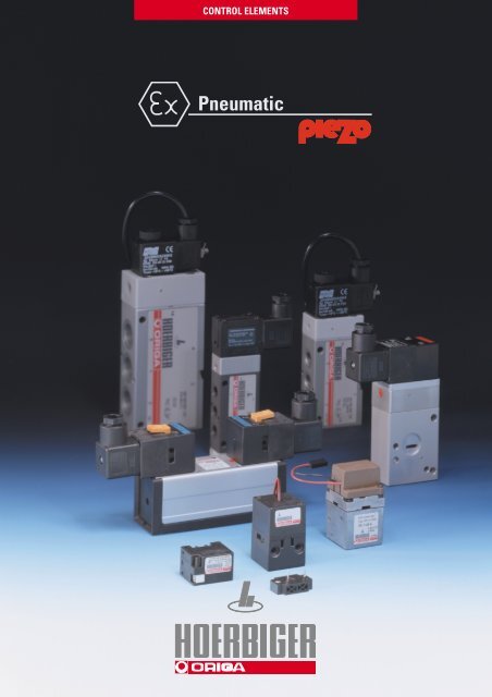
CONTROL ELEMENTSPneumatic
HOERBIGER-ORIGA... For fast and effective automation solutionHOERBIGER-ORIGA is a manufacturer and supplier of pneumaticallydriven components and systems designed to solve movement tasksfor a variety of branches of machine construction and automationengineering. Special products and solutions for hazardous areascompliment the extensive programme.Area‘s of competencein welding technologyin the automobileindustryin the paper industryin clean roomtechnologyOur ServiceHOERBIGER-ORIGA offers itspartners competent, on-sitesupport world-wide.Your HOERBIGER-ORIGApartner provides you withprofessional consulation anddetailed technical supportquickly and efficiently.Attenatuely you may obtaindata relevant to your needsfrom our web site.Technical data sheets as wellas 2D and 3D drawings ofour entire standard componentsare available in nearlyevery major CAD format.Das Programm • Product RangeGamme de Produits • Gamma di ProdottiEl ProgrammaYou can also receive additionalinformation from ourtechnical catalogues, whichare also available inelectronic format either onCD ROM or from our homepageon the Internet.in the chemical industryin hazardous systemswww.hoerbiger-origa.comwww.interact-system.comwww.airfit.comwww.hoerbiger.comin medical technology2
ContentsPageHow do piezo valves work? ............................................... 6General purpose valvesOverview and ordering data.............................................. 7-9Applications ........................................................................ 103/2 way miniature piezo valves andpilot control element – Series P9 ...................................... 113/2 way switching piezo valves - Series P10 .................... 123/2 way piezo valves - Series P20-OEM ............................ 13Proportional pressure control valve– Series PR-U-OEM............................................................. 14PageAccessoriesP supply manifolds for directional valvesSeries S9-1/8, S9-1/4, S9-1/2 .............................................. 41-45RPS supply manifolds for directional valvesSeries S9-1/8, S9-1/4, S9-1/2 .............................................. 46-47Single base plates to ISO 5599, size 1, 2, 3for Series S20 ..................................................................... 48Base plate combinations to ISO 5599Size 1, 2, 3 for Series S20 .................................................. 49-51Compatibility with market leadersfor control systems ................................ 52-53Directional valves with NAMURmounting pattern– intrinsically safe and withEEx m-solenoids 15-20Overview and ordering data........................................... 16Characteristics ................................................................. 17– intrinsically safe valves (piezo valves)3/2-, 4/2- and 5/2 way valves G1/4, Series S29 .............. 18– valves with EEx m-solenoids5/2 way valves G1/8, Series S9 ....................................... 193/2-, 4/2- and 5/2 way valves G1/4, Series S9 ................. 20Directional valvesin-line and base plate design– intrinsically safe and withEEx m-solenoids 21-40Overview and ordering data.............................................. 22-26Characteristics .................................................................... 27-29– intrinsically safe valves (piezo valves)3/2 way poppet valves NW 1.6, M5, Series P8 .............. 303/2 way poppet valves NW 2, G1/8, Series P20 ............. 313/2 way valves G1/4, Series S9 ....................................... 325/2 and 5/3 way valves G1/8, Series S9 .......................... 335/2 and 5/3 way valves G1/4, Series S9 .......................... 345/2 and 5/3 way valves, Series S9- base plate design to ISO 5599 ...................................... 35– valves with EEx m-solenoids3/2 way poppet valves NW 1.3, Series V9 ...................... 363/2 way valves G1/8, G1/4, G1/2, Series S9 .................... 375/2 way valves G1/8, G1/4, G1/2, Series S9 .................... 385/3 way valves G1/8, G1/4, G1/2, Series S9 .................... 395/2 and 5/3 way valves, Series S9- base plate design to ISO 5599 ...................................... 403
HOERBIGER-ORIGA ValvesEx-Facts and Marking (Europe)EEx ia IIC T4 / T5 / T6EExCertified according to European Standard CENELECHOERBIGER-ORIGA Valves are certified additionelly by the new ATEX 100a-Standard, Directive 94/9/EC,required July1, 2003Explosion Proofedi (a)IICT4/T5/T6Type of Protectioni – Intrinsic Safety (→ Zone 0,1,2)Technically different m – Encapsulation (→ Zone 1,2)principles of protection o – Oil Immersionp – Excess Pressuredia: no ignition if: normal use + 1 fault q – Powder Filledor combination of 2 faults (zone 0, 1, 2) e – Increased Safetyib: no ignition if: normal use + 1 fault (zone 1, 2) d – FlameproofApparatus GroupingTypical Gas Minimum Ignition EnergyDegree of ignition ability IIC Acetylene 20 µJfor different gases IIC Hydrogen 20 µJIIB Ethylene 60 µJIIA propane 180µJTemperature ClassIEC 79-8 Maximum Surface Minimum IgnitionT-Class Temperature Temperature of a gasT1 450 °C > 450 °CT2 300 °C > 300 – ≤ 450 °CT3 200 °C > 200 – ≤ 300 °CHighest permissible T4 135 °C > 135 – ≤ 200 °Csurface temperature of T5 100 °C > 100 – ≤ 135 °Can equipment part T6 85 °C > 85 – ≤ 100 °CArea ClassificationZone 0 (gases) danger present continuosly (> 1000 hours per year)Zone 1 (gases) danger present intermittently (10 – 1000 hours per year)Zone 2 (gases) danger present abnormally (0 – 10 hours per year)Amount of probability of existing danger, fixes the protection type.(Compatible HOERBIGER-ORIGA Valves specifications are marks red)4
in Explosion AreasOut 24VProfibus DPPLC / PLSEEx i - BarrierDPPAProfibus DP-PAGatewayOut EEx iStandard ValvesValve BoxOut EEx iProfibus PAOut PA Out EEx iRemote ProcessInterface (RIO)Serie S9 Serie P8 Serie S29 Serie S20 Serie S9 Serie S9 Serie V9 Serie S20E/P-Converter for PositionerProfibus PAProcess Valvewith 2-wire Positioner<strong>Piezo</strong> TechnologySerieP9SerieP10SerieP20SerieP21SeriePRU-OEMSolenoidTechnologyCustomer spezifiedE/P-Converter... EEx ia IIC T4/T5/T6... EEx mZone 0, 1, 2Zone 1, 25
How do piezo valves work?Design and functionThe central element is a<strong>Piezo</strong>-ceramic bendingelement which is built upof several layers, rather likea bimetallic strip. When anelectrical voltage is applied,this element bends a fewhundredths of a millimetre.This bending allows air toenter the piezo valvethrough port 1 to port 2(Fig. 2). In the unactuatedmode, the air can flow fromport 2 to port 3 (Fig. 1).Depending on the voltageapplied, the lesser or greaterbending of the elementgenerates an analoguepressure signal at port 2.The piezo valve can thereforebe used either as aswitching valve or as a proportionalvalve. Optimizedversions for either switchingor proportional use areavailable.When the P8-valve (Fig.3) iselectrically actuated (ONcondition),the signal that isfiltered and prepared by thecontrol electronics opens thesupply air seat in the piezovalve. The activated controlcircuit actuates the integratedvalve – air flows from1 to 2. A pressure regulatorand a micro-filter areconnected in series beforethe piezo valve.Fig. 1Fig. 2--22OFF+ON+3131Fig. 3 Fig. 4Connecting plugConnecting plugActuating electronicsActuating electronics<strong>Piezo</strong> Valve<strong>Piezo</strong> Valve332211PressureregulatorPressureregulatorMicrofilterMicrofilterOFF conditionON condition6
General purpose valves7
General purpose valvesOverview3/2 Way <strong>Piezo</strong> Miniature Valves and Pilot Valves – Series P9Description Symbol Order Instructions PageTypeOrder No.Switching valve, 2P9-NG-S-L PS 11010-11L 111210normally closed(+pole on the left side)1 3Switching valve, 2P9-NO-S-L PS 11010-21L 111012normally closed(+pole on the left side)1 3Proportional valve,2P9-NG-P-LR PS 11010-31LR 11normally closed1210(+pole on the rightand left side)1 3Proportional valve, P9-NO-P-LR PS 11010-41LR 112normally open1012(+pole on the rightand left side)1 33/2 Way Chip Valves (<strong>Piezo</strong> Miniature Switching Valve) – Series P10 *Version Symbol Order Instructions PageTypeOrder No.3/2 way switching valve 2P10-3S-NG-D-010 PS11400-010-A 121210normally closed0.1 bar version1 33/2 way switching valve 2P10-3S-NG-D-030 PS11400-030-A 121210normally closed0.3 bar version1 33/2 way switching valve 2P10-3S-NG-D-060 PS11400-060-A 121210normally closed0.6 bar version1 33/2 way switching valve 2P10-3S-NG-D-120 PS11400-120-A 121210normally closed1.2 bar version1 33/2 way switching valve 2P10-3S-NG-D-200 PS11400-200-A 121210normally closed2.0 bar version1 3* on request:3/2 way switching valve, normally open2/2 way switching valve, normally closed and normally open3/2 way proportional control valves, normally closed and normally open2/2 way proportional control valves, normally closed and normally open8
3/2 Way <strong>Piezo</strong> Valves NW 2 – Series P20-OEMVersion Symbol Order Instructions PageTypeOrder No.Pilot valve, 12210 P20 381RF-NG-COEM PS10021-001A 13normally closed1 3Pilot valve, 2P20 381RF-NO-COEM PS10022-001A 1310 12normally open1 3Base plate PS10531-A-01 31Base Plates see page 31Proportional Pressure Regulating Valve NW 2 – Series PR-U-OEMDescription Symbol Order Instructions PageTypeOrder No.Proportional pressure PR-U-OEM PS11193-A 143regulating valve12Base plate G1/8 PS11112-A-01 149
General purpose valvesActuator applicationsIn the following configurations piezo valves can be suppliedfor use in modern actuators.Supply of P9 or P10 piezo chips as switching or proportionalpilot valvesThese provide the user with the highest degree of flexibilityin the design of dedicated digital or analog actuator systems(IP converter with amplifier) as stand-alone devices or as partof large-scale positioning systems.212 10<strong>Piezo</strong> valvetype P9-NG-S-.Scope of supply of HOERBIGER products1 3210 121 3<strong>Piezo</strong> valvetype P9-NG-S-.Amplifier and actuator providedby customerSupply of P20-OEM digital piezo valves consisting of piezochip (pilot valve) and volume amplifierScope of supply of HOERBIGER products2212 1010 121 3<strong>Piezo</strong> valvetype P20 381RF-NG-COEM1 3<strong>Piezo</strong> valvetype P20 381RF-NG-COEMActuator provided by customerSupply of analog PR-U-OEM piezo valve consisting of piezochip (pilot valve) and proportional main valveScope of supply of HOERBIGER products23 1<strong>Piezo</strong>prop. pressure regulatingvalve PR-U-OEMActuator provided by customerCustomer-specific solutionsComplete development and delivery of customer-specificactuator control systems as part of a joint developmentproject.Customer-specific solutionHOERBIGER Interface provides a comprehensive supportpackage for the installation and application of all variants.10
General purpose valves3/2 Way <strong>Piezo</strong> Valve Series P9-OFF+3-ON+33/2 Way <strong>Piezo</strong>Miniature ValveandPilot ValveSeries P9212Characteristics Symbol Unit DescriptionGeneral FeaturesSystemDirectly actuated 3/2 way proportionalpoppet valveHousingPlasticMounting Flange (see dimensional drawing) **Port size = NW 0.33Weight g 6Flow direction ON: from 1 to 2OFF: from 2 to 3Installation positionOptionalAmbient ϑ min°C -30 Note:temperature range ϑ max°C +80 When using below freezingpoint please contact ourtechnical departmentPneumatic CharacteristicsOperating pressure p Nbar 1.2 (other pressures between 0 and 2 baron request)Nominal flow Q Nl/min 1.5Medium Filtered air (5 µ) *Leakage Q Ll/min On: 0.15 maxOff: 0.10 maxElectrical CharacteristicsOperating voltage U NV 24 DC ***(other voltages on request)Capacity C nF < 100Switching energy E mWs 0.014Holding energy P W 0Switching time t ms < 2ConnectionContact pins – ø 0.8 mm* other fluids on request** observe installation recommendations*** observe control recommendations1Versions– Proportional valve– Switching valve– NC or NOSpecial Versions– Special pressure ranges– 2/2 way valve<strong>Piezo</strong> ChipTyp:e P9-..-.-..1912,631ø 11 33020,6***11,711,721,211,740,87,711 1014,12* + pole on the right side** + pole on the left sideDimensions in mm11
General purpose valves... the “Chip Valve” Series P10”Chip Valve”<strong>Piezo</strong> MiniatureValveSeries P10Versions– 3/2 way switching valvesnormally closed (NG)Special Versions (4(on request)–3/2 way switching valvesnormally open (NO)–2/2 way switching valves–3/2 way proportionalcontrol valves–2/2 way proportionalcontrol valves (4normally closed andnormally open versionsScope of supply–1 valve– Mounting kit consistingof 3 rollers and O-rings– 2 M2.5 x 25 mm screws– 2 EJOT 2.5 x 6 screws–1 connecting cable2 x 0.14, 300 mm,with connector(1Normally open (NO)version on request(2Nominal pressure p Nagainst atmosphere(3Voltages < 24 V on request(not for prop. control valves)(4Characteristics on request(5Not suitable as safetyvalve with 100% EDCharacteristics Symbol Unit DescriptionGeneral FeaturesSystemDirectly controlled (from system) proportionalcontrol or switching poppet valveMountingMetal screws(part of scope of supply)ConnectionFlange or nose nozzle (3 mm)Port size NW ca. 0.33Installation positionOptionalWeight g 20Flow direction ON: from 1 to 2(normally closed NG) (1OFF: from 2 to 3 (3/2-Way valve)Medium and ϑ min°C 0 other temperaturesambient temperature ϑ max°C +50 on requestrangeMediumFiltered air (30µ), other gases or fluidspossible on requestPneumatic CharacteristicsValve nominal pressure pN bar 0.1 bar 0.3 bar 0.6 bar 1.2 bar 2.0 barInput pressure range p1 min/max bar 0.05–0.15 0.2–0.3 0,5–0.7 1.1–1.3 1.8–2.2Output pressure range p2 min/max bar 0–0.1 0–0.3 0–0.6 0–1.2 0–2.0(proportional version)Flowrate (23/2 way models Q l/min 0.5 0.9 1.5 1.5 1.4Leckageinlet air side 4% of Qoutlet air side: 8% of QElectrical CharacteristicsOperating volatage UN V 24 DC (proportional control valve 0 – 24 V DC) (3Holding energy P W 0.006ConnectionRelative switching time ED % 100 (5Electrical protection IP 20Chip ValveType: P10-..-..-.-...2-pin connectorFlange mounting kitconsisting of 3 rollersand O-ringsfor M2.5 x 25screws20,512,54316for EJOT 2.5x6 screwson front and rear1 21 223,533332,64 26,933,51 282,6243,8272,0283,822ø312
3/2 Way <strong>Piezo</strong> Valve Series P20-OEMSeries P20-OEM – NW 2.0Characteristics Symbol Unit DescriptionGeneral FeaturesSystemPoppet valve system,pneumatic pilot control withpiezo valve, some overlapMountingFlange (see dim. drawing)Pipe connectionFlangePort sizeNW2Weight (mass) kg 0.100Flow direction ON: from 1 to 2OFF: from 2 to 3 (1Installation positionOptionalMedium and ϑmin. / max. °C -10 to +60ambient temperatureNote: Contact technical departrangement advice if used intemperatures between-30 and +80°CMediumDry or filtered air (30µ), no orminimal oil mist lubrication(max. 30mg/m 3 )3/2 Way<strong>Piezo</strong> ValveSerie P20-OEMNW 2Versions– normally closed (NG)– normally open (NO)Note:The valve for the P20-OEMseries fulfils the requirementsfor approval as anintrinsically safe device whenused with an appropriatecontroller.Pneumatic CharacteristicsNominal pressure pmin. / max. bar 6Operating pressure pmin. / max. bar 1.5 – 8Nominal flow QN l/min 130 (from 6 to 5 bar)Nominal size mm 2.0Electrical CharacteristicsNominal voltage UN V DC 24Capacity C nF < 100Switching energy E mWS 0.014Holding energy P W 0Duty cycle ED % 100ConnectionCable 300 mm longSwitching time tON ms < 20 (10% of discharge pressure)tOFF ms < 20 (90% of discharge pressure)Electrical protection IP 20 ( 2( 1 outlet air not included( 2 not suitable as safety valve with 100% EDType: P20 381RF-.-COEM3Connecting cable 300 mm242,5M47,5116532,52132,5Base plate see page 3113
General purpose valvesProp. Pressure Regulating Valve Series PR-U-OEMPressure RegulatingValveSeries PR-U-OEMNW 2 and G1/8Proportional valve with<strong>Piezo</strong> pilotNote:The valve for the PR-U-OEMseries fulfils the requirementsfor approval as anintrinsically safe devicewhen used with anappropriate controller.<strong>Piezo</strong> valveA piezo valve is used asthe pilot control element.The piezo valve generatesa pilot pressure in the pilotchamber of the main valveproportional to the controlvoltage.The supply for the piezovalve is tapped off from thecontrol air connection 1 andpassed through a pressureregulator and filter.Connection321Series PR-U-OEM – NW 2.5Characteristics Symbol Unit DescriptionGeneral FeaturesTypeMembrane pressureregulating valve, pneumaticpilot control with piezo valve,some overlapMountingFlange (see dim. drawing)ConnectionFlangePort sizeNW2.5Weight (mass) kg 0.100Flow direction ON: from 1 to 2OFF: from 2 to 3 (1InstallationIn any positionMedium and ϑmin. / max. °C -30 to +80ambient temperaturerangeNote:When using belowfreezing point it is necessaryto consult us.Medium Dry or filtered air (30µ),no or minimal oil mistlubrication (max.30mg/m 3 )Pneumatic CharacteristicsNominal pressure pmin. / max. bar 6Operating pressure pmin. / max. bar 1.5 – 10Nominal flow QN l/min 200 (from 6 to 5 bar)Nominal size mm 2.6Electrical CharacteristicsInput voltage U V DC 0 – 24 ( 3Capacity C nF < 100Switching energy E mWS 0.014 (from 0 to 24 V)Holding energy P W 0ConnectionConnecting cable 200 mm2-pin AMP connectorGrid size 2.54Electrical protection IP 20( 1 outlet air not included( 2 The device should only be used in a closed control loop.A 0-24 V DC controller should be provided (see U/P diagram).Pressure Regulating ValveType: PR-U-OEMPressureRegulatorMicrofilter1 = Pressure supply (P)2 = Outlet (A)3 = Exhaust (R)U/P-Diagramp 2(bar)800 8 18 24U(V)The operating voltage rangeof the valve may fluctuatedue to temperature or longtermeffects.A control range of 0 to 24 Vmust therefore be designedinto the controller.3(*Base Plate G1/8122516677G1/84,57,57,551172414203637(* Connecting cable 200 mm32201514M324,5G1/814
Directional Valves with NAMUR Connections15
Directional Valves with NAMUR ConnectionsOverviewIntrinsically safe 3/2, 4/2 and 5/2 Way Valves with NAMUR Connection – Series S29Actuation Symbol Order Instructions PageTypeOrder No.2Electrical, 1210 S29 385RF-1/4-.-NAMUR PS 13623-..6A 18by permanent signal1 34 2Electrical, S29 485RF-1/4-.-NAMUR PS 13621-..6A 181410by permanent signal1 3Electrical,4 214 12 S29 585RF-1/4-.-NAMUR PS 13619-..6A 18by permanent signal5134 2Electrical,14 12S29 585-1/4-.-NAMUR PS 13620-..6A 21by impulse5132Pilot valve as spare part 1210 P29 381 RF-NG-C. PS 10041-..1A –(electrical,by permanent signal)1 3Version Nominal voltage Type key Key codeIntrinsically safe 6 – 9 V DC M 54II 2G EEx ia IIC T4/T5/T6 7 – 16 V DC N 5112 – 24 V DC L 5524 – 30 V DC E 213/2, 4/2 and 5/2 Way Valves with EEx m-Solenoids and NAMUR Connection – Series S9Actuation Symbol Order Instructions PageTypeOrder No.2Electrical, 1210S9 381RF-1/4-NG-SO-.. PD 33854-..33 20by permanent signal1 34 2Electrical, S9 481RF-1/4-SO-.. PD 40996-..33 201410by permanent signal1 34 2Electrical, 1412S9 581RF-1/8-SO-.. PD 34143-..33 19by permanent signal S9 581RF-1/4-SO-.. PD 34985-..33 205134 2Electrical, 1412S9 581-1/8-SO-.. PD 34984-..33 19by impulse S9 581-1/4-SO-.. PD 34986-..33 20513Solenoid version Nominal voltage Key codeCasting cover 24V = 48EEx m II T5 220V/50(60) Hz 98other voltages on request16
CharacteristicsSeries S29 – G1/4 and S9 – G1/8 -1/4Characteristics Symbol Unit Series S29, S9G1/8 G1/4Actuation Electrical ElectricalpilotedpilotedGeneral FeaturesType Spool valve Spool valveMounting 2 screws M5 2 screws M6Tube connection Thread and NAMUR connection Thread and NAMUR connectionThread G1/8 – 7.4 deep G1/4 – 11 deepWeight kg See page 18 see page 19, 20Installation In any position in any positionAmbient temperature range ϑmin. / max. °C -10 to +60 Note: When using below freezing pointMedium temperature range ϑmin. / max. °C -10 to +60 please contact our technical departmentMedium Filtered compressed air (30µ)Lubrication With or without oil mist lubrication ( 1(we recommend the use of mineral oil type VG 32 to ISO 3448)Pneumatic CharacteristicsNominal pressure pmin. / max. bar 6 6Operating pressure range– Permanent signal range pmin. / max. bar 2–8 (Series S29), 2–10 (Series S9) 2–8 (Series S29), 2–10 (Series S9)– Impulse range pmin. / max. bar 1.5–8 (Series S29), 1.5–10 (Series S9) 1.5–8 (Series S29), 1.5–10 (Series S9) ( 2Nominal flow QN l/min 500 (450 at 3/2-way valve) 1300 ( 3ActuationActuation pressure range– Permanent signal range pmin. / max. bar 2–8 (Series S29), 2–10 (Series S9) 2–8 (Series S29), 2–10 (Series S9)– Impulse range pmin. / max. bar 1.5–8 (Series S29), 1.5–10 (Series S9) 1.5–8 (Series S29), 1.5–10 (Series S9) ( 2Electrical piloted ● ●<strong>Piezo</strong> Electrical Actuation ( 4ConformityEU type test certificate DMT 01 ATEX E 025 X, DMT 01 ATEX E 026 XCategoryII 2G EEx ia IIC T4/T5/T6HOERBIGER-Code M N L EVoltageDCSwitching voltage U V/DC 6 – 9 7 – 16 12 – 24 24-30Initial current I mA – – – 1,6Permanent currant I mA 1 – 2 2 – 5.5 1.5 – 3.5 0.24 – 0.3Electrical protectionConnectionPlug to DIN 43650ASafety data according to EU type test certificateVoltage Ui V 9 16 24 30Current Ii mA – – – 150Outer capacity Ci nF 12 12 12 12Outer inductivity Li nH 120 120 120 120Electrical, EEx m-solenoidsClass of protectionEEx mVoltage AC DCNominal voltage Un V 220 24 other voltages on requestInitial power consumption VA (W) 5.0 5.1Continuous consumption VA (W) 5.0 5.1Electrical protectionInsulating material E to VDE 0580ConnectionCable 1200 mm long( 1 at piezo electrical actuated valve: dried or filtered air (30µ), nor or minimal oil mist lubrication (max.30mg/m 3 )( 2 at differential piston version 2.5 – 8 bar (Series S29), 2.5–10 (Series S9)( 3 at version middle position exhausted 1000 l/min( 4 not suited as safety valve with 100% ED17
Directional Valves with NAMUR ConnectionsSeries S29 – intrinsically safe, piezo electrical actuated3/2, 4/2 and5/2 Way ValveSeries S29G1/43/2 Way valveType: S29 385RF-1/4-.- Namur32with NAMUR connectionsActuation:– <strong>Piezo</strong> electric actuatedThe delivery includes:1 Valve2 Mounting screws1 Coding pin2 O-rings24 29,5125.5 x 3 deep5,2143219,5123231G1/4657,540,52283,519,5121,5~ 140~ 216only atimpulse valves52Weight (mass) kgDescription Type Weight (mass)Electrical, by perm. signal S29 385RF-1/4-.-NAMUR 0.460Electrical, by perm. signal S29 485RF-1/4-.-NAMUR 0.550Electrical, by perm. signal S29 585RF-1/4-.-NAMUR 0.550Electrical, by impulse S29 585-1/4-.-NAMUR 0.6504/2 and 5/2 Way ValveType: S29 4(5)85RF-1/4-.- Namur, S29 585-1/4-.- Namur328024 30,5125,5 x 3 deep5,2143451G1/440,522105,5143,5~ 162~ 237221257,519,56219,5332only atimpulse valves5280Order Instructions see page 16, Characteristics see page 1718
**Series S9 – with EEx m-Solenoids5/2 Way valveType: S9 581RF-1/8-SO-.., S9 581-1/8-SO-..5/2 Way ValveSeries S9G1/8with NAMUR connections~ 208225,224125.5 x 3 deep31419,54243212513G1/828561633,5181887,515,5128~ 140The delivery includes:1 Valve2 Mounting screws1 Coding pin2 O-ringsActuation:EEx m-solenoids–Electrical pilot operation15,540impulse valves only22~71* Manual override30Weight (mass) kgDescription Type Weight (mass)Electrical, by perm. signal S9 581RF-1/8-.. 0.280Electrical, by impulse S9 581-1/8-.. 0.415Order Instructions see page 16, Characteristics see page 17P-supply and RPS manifolds see page 41, 42, 46Dimensions in mm19
*Directional Valves with NAMUR ConnectionsSeries S9 – with EEx m-Solenoids3/2, 4/2 and5/2 Way ValveSeries S9G1/43/2 Way valveType: S9 381RF-1/4-SO-..3230with NAMUR connectionsActuation:EEx m-Solenoids– Electrical pilot operationThe delivery includes:1 Valve2 Mounting screws1 Coding pin2 O-rings*24 29,512*5.5 x 3 deep5,2143219,5123231G1/440,52283,519,5121,532302210614812*5,21493451219,53622057,5~ 140~ 216* Manual override52~ 71impulsevalves onlyWeight (mass) kgDescription Type Weight (mass)Electrical, by perm. signal S9 381RF-1/4-.. 0.500Electrical, by perm. signal S9 481RF-1/4-.. 0.600Electrical, by perm. signal S9 581RF-1/4-.. 0.600Electrical, by impulse S9 581-1/4-.. 0.7004/2 and 5/2 Way valveType: S9 4(5)81RF-1/4-SO-..,S9 581-1/4-SO-..24 30,5125.5 x 3 deep20,7 32,7G1/441~ 159~ 23122321252~ 7115,5impulsevalves only* Manual overrideOrder Instructions see page 16, Characteristics see page 17P-supply and RPS manifolds see page 43,44,4720
Directional Valves, intrinsically safe and with EEx m-Solenoids21
Directional Valves – intrinsically safe, piezo electrically actuated, Series P8, P20 – M5 to G1/8Overview and Order Instructions3/2 Way Poppet Valves (Pilot and Single Valves) – Series P8Actuation Symbol Port size Order Instructions PageTypeOrder No.Pilot valve (1 12210 NW 1.6 P8 381RF-NG-S. PS 11001-..0A 30normally closed1 32normally open 10 12 NW 1.6 P8 381RF-NO-S. PS 10002-..0A 301 3212 10Single valve M5 (2 M5 P8 381RF-M5 NG-S. PS 11003-..0A-01 30normally closed(1without base plate and without plug(2with plug and with base plate1 3Version Nominal voltage Type key Key codeIntrinsically safe 6 – 9 V DC M 54II 2G EEx ia IIC T4/T5/T6 7 – 16 V DC N 5112 – 24 V DC L 5524 – 30 V DC E 213/2 Way Poppet Valves (Pilot and Single Valve) – Series P20Actuation Symbol Port size Order Instructions PageTypeOrder No.212 10Pilot valve (1 NW 2 P20 381RF-NG-C. PS 10021-..1A 31normally closed1 32normally open 10 12 NW 2 P20 381RF-NO-S. PS 10022-..1A-01 311 3212 10Single valve G1/8 (2 G1/8 P20 381RF-1/8NG-C. PS 10023-..1A-01 31normally closed(1without base plate and without plug(2with plug and with base plate1 3Version Nominal voltage Type key Key codeIntrinsically safe 6 – 9 V DC M 54II 2G EEx ia IIC T4/T5/T6 7 – 16 V DC N 5112 – 24 V DC L 5524 – 30 V DC E 21Base Plates and Accessories for Series P8 and P20Series P8Description Type Order No.Base plate for 1 valvePS11614-A-01Base plate for 2 valvesPS11614-A-02Base plate for 4 valvesPS11614-A-04Base plate for 6 valvesPS11614-A-06Base plate for 8 valvesPS11614-A-08Base plate for 10 valvesPS11614-A-10Blanking plate, completePS11530-APlug GSD-22 KY9393Series P20Description Type Order No.Base plate for 1 valvePS10531-A-01Base plate for 2 valvesPS10531-A-02Base plate for 4 valvesPS10531-A-04Base plate for 6 valvesPS10531-A-06Base plate for 8 valvesPS10531-A-08Base plate for 10 valvesPS10531-A-10Blanking plate, completePS10559-APlug GSD-30 KY563722
Directional Valves – intrinsically safe, piezo electrically actuated, Series S9-G1/8, G1/4, S20- ISO 1, 2, 3Overview and Order Instructions3/2 Way Valves – Series S9Actuation Symbol Order Instructions PageTypeOrder No.2Electrical, 10S9 385RF-1/4-. PS 13204-..6A 32by permanent signal1 3212 10Electrical, S9 385-1/4-. PS 13200-..6A 32by impulse1 35/2 Way Valves – Series S9Actuation Symbol Order Instructions PageTypeOrder No.4 2Electrical, S9 585RRF-1/8-. PS 13118-..6A 3314 12by permanent signal S9 585RF-1/4-. PS 13210-..6A 345134 214 12Electrical, S9 585-1/8-. PS 13104-..6A 33by impulse S9 585-1/4-. PS 13222-..6A 345135/3 Way Valves – Series S9Actuation Symbol Order Instructions PageTypeOrder No.4 2Electrical, by permanent 14 12S9 585RFG-1/8-. PS 13108-..6A 33signal with spring return S9 585RFG-1/4-. PS 13212-..6A 34to middle position5134 2Electrical, by permanent 14 12S9 585RFE-1/8-. PS 13109-..6A 33signal with spring return S9 585RFE-1/4-. PS 13213-..6A 34to middle position5134 2Electrical, by permanent 14 12S9 585RFB-1/8-. PS 13110-..6A 33signal with spring return S9 585RFB-1/4-. PS 13214-..6A 34to middle position5135/2 and 5/3 Way Valves to ISO 5599 – Sizes 1, 2, 3 – Series S20Actuation Symbol Order Instructions PageTypeOrder No.4 2Electrical, 14 12S20 585RF-1-.. PS 13704-..1A 35by permanent signal, S20 585RF-2-.. PS 13724-..1Aspring return 513S20 585RF-3-.. PS 13744-..1A4 2Electrical, 1412S20 585R-1-.. PS 13702-..1A 35by permanent signal, S20 585R-2-.. PS 13722-..1Aair spring return 513S20 585R-3-.. PS 13742-..1A4 2Electrical, 14 12S20 585-1-.. PS 13700-..1A 35by impulse S20 585-2-.. PS 13720-..1A513S20 585-3-..PS 13740-..1AElectrical,144 212S20 585RFG-1-.. PS 13706-..1A 35by permanent signal,S20 585RFG-2-.. PS 13726-..1Awith spring return513S20 585RFG-3-.. PS 13746-..1Ato middle position4 214 125134 214 12513S20 585RFB-1-.. PS 13710-..1A 35S20 585RFB-2-.. PS 13730-..1AS20 585RFE-1-.. PS 13708-..1A 35S20 585RFE-2-.. PS 13728-..1AS20 585RFE-3-.. PS 13748-..1AVersion Nominal voltage Type key Key codeIntrinsically safe 6 – 9 V DC M 54II 2G EEx ia IIC T4/T5/T6 7 – 16 V DC N 5112 – 24 V DC L 5524 – 30 V DC E 212323
Directional Valves – with EEx m-Solenoids, Series S9 (V9) – G1/8 to G1/2Overview and Order Instructions3/2 Way Valves – Standard Versions with EX-Proof-SolenoidsActuation Symbol Order Instructions PageTypeOrder No.2Electrical, S9 381RF-1/8-NG-.. PA 10297-..33 371210by permanent signal S9 381RF-1/4-NG-.. PA 12716-..33S9 381RF-1/2-NG-.. PA 16412-..33101 321 31 3122with external pilot air1412S9 381S-RF-1/8-.. PA 10300-..33 37pst2Electrical, 14 12 S9 381S-1/8-.. PA 10301-..33 37with external pilot air pst 1 3 pst S9 381S-1/2-.. PA 16417-..33pstElectrical, NW 1.3 212 10V9 381RF-1/8-NG-.. PA 10362-..33 36131 3pstS9 381RF-1/8-NO-.. PA 10298-..33 37S9 381RF-1/4-NO-.. PA 12717-..33S9 381RF-1/2-NO-.. PA 16413-..33S9 381S-RF-1/4-.. PA 12719-..33S9 381S-RF-1/2-.. PA 16415-..332Electrical, 12 10 S9 381-1/8-.. PA 10299-..33 37by impulse S9 381-1/4-.. PA 12718-..331 3S9 381-1/2-.. PA 16414-..33by impulse S9 381S-1/4-.. PA 12720-..332Electrical, S9 382-1/4-.. PA 12721-..33 3714 12by impulse, S9 382-1/2-.. PA 16418-..33differential piston1 3with external pilot air214 12 S9 382S-1/4-.. PA 12722-..33 37S9 382S-1/2-.. PA 16419-..33by permanent signal2NW 1.3 10 V9 381H-RF-1/8-NG-.. PA 10363-..33 36121 32NW 1.31210 V9 381H-RF-1/8-NO-.. PA 10367-..33 361 35/2 Way Valves – Standard Versions with EX-Proof-SolenoidsActuation Symbol Order Instructions PageTypeOrder No.4 2Electrical, 1412 S9 581RF-1/8-.. PA 10312-..33 38by permanent signal S9 581RF-1/4-.. PA 12679-..33513S9 581RF-1/2-.. PA 16171-..334 2with external pilot air 1412 S9 581S-RF-1/8-.. PA 10314-..33 38pst5134 2Electrical,1412S9 581-1/8-.. PA 10313-..33 385 134 214 12S9 581S-RF-1/4-.. PA 12681-..33S9 581S-RF-1/2-.. PA 16174-..33by impulse S9 581-1/4-.. PA 12680-..33513S9 581-1/2-.. PA 16172-..334 2with external pilot air14 12 S9 581S-1/8-.. PA 10315-..33 38S9 581S-1/4-.. PA 12682-..33pstpst S9 581S-1/2-.. PA 16175-..334 2Electrical, S9 582-1/4-.. PA 12683-..33 3814 12by impulse, S9 582-1/2-.. PA 16173-..33differential piston5 1 3with external pilot air S9 582S-1/4-.. PA 12684-..33 38pst513pstSolenoid version Nominal voltage Key codeEX-proof version 24V = 48220V/50(60) Hz 98Further voltages available on request24
Directional Valves – with EEx m-Solenoids, Series S9 – G1/8 to G1/2Overview and Order Instructions5/3 Way Valves – Standard Versions with EX-Proof-SolenoidsActuation Symbol Order Instructions PageTypeOrder No.Electrical,by permanent signalwith spring returnto middle position4 214 125134 214125134 21412513S9 581RFG-1/8-.. PA 10333-..33 39S9 581RFG-1/4-.. PA 12705-..33S9 581RFG-1/2-.. PA 16176-..33S9 581RFE-1/8-.. PA 10334-..33 39S9 581RFE-1/4-.. PA 12706-..33S9 581RFE-1/2-.. PA 16177-..33S9 581RFB-1/8-.. PA 10335-..33 39S9 581RFB-1/4-.. PA 12707-..33S9 581RFB-1/2-.. PA 16178-..33Solenoid version Nominal voltage Key codeEX-proof version 24V = 48220V/50(60) Hz 98Further voltages available on request25
Directional Valves to ISO 5599 – with EEx m-Solenoids, Series S20Overview and Order Instructions5/2 Way Valves – Standard Version with EX-Proof-Solenoids to ISO 5599 – Sizes 1, 2, 3Actuation Symbol Order Instructions PageTypeOrder No.4 2Electrical, 1412S20 581RF-1-.. PA 12875-..33 40by permanent signal S20 581RF-2-.. PA 16441-..33with spring return 513S20 581RF-3-.. PA 16442-..334 2with external pilot air 1412S20 581S-RF-1-.. PA 12882-..33 40pst5134 2Electrical, 1412 S20 581R-1-.. PA 12876-..33 40513Electrical,4 21412 S20 581-1-.. PA 12874-..33 404 214 12S20 581S-RF-2-.. PA 16456-..33S20 581S-RF-3-.. PA 16462-..33by permanent signal S20 581R-2-.. PA 16444-..33with air spring return S20 581R-3-.. PA 16445-..33by impulse S20 581-2-.. PA 16438-..33513S20 581-3-.. PA 16439-..33with external pilot air S20 581S-1-.. PA 12880-..33 40S20 581S-2-.. PA 16454-..33pst 5 13pstS20 581S-3-.. PA 16460-..335/3 Way Valves – Standard Version with EX-Proof-Solenoids to ISO 5599 – Sizes 1, 2, 3Actuation Symbol Order Instructions PageTypeOrder No.Electrical,by permanent signalwith spring returnto middle position4 214 121414pst51345134225135131212pst4 214 12pst513pst4 214 12pst513pstS20 581RFG-1-.. PA 12877-..33 40S20 581RFG-2-.. PA 16447-..33S20 581RFG-3-.. PA 16448-..33S20 581RFB-1-.. PA 12879-..33 40S20 581RFB-2-.. PA 16453-..33S20 581RFE-1-.. PA 12878-..33 40S20 581RFE-2-.. PA 16450-..33S20 581RFE-3-.. PA 16451-..33with external pilot air 4 2S20 581S-RFG-1-.. PA 12883-..33 4014 12S20 581S-RFG-2-.. PA 16457-..33S20 581S-RFG-3-.. PA 16463-..33S20 581S-RFB-1-.. PA 12885-..33 40S20 581S-RFB-2-.. PA 16459-..33S20 581S-RFE-1-.. PA 12884..33 40S20 581S-RFE-2-.. PA 16458..33S20 581S-RFE-3-.. PA 16464..33Solenoid version Nominal voltage Key codeEX-proof version 24V = 48220V/50(60) Hz 98Further voltages available on request26
Directional Valves – intrinsically safe, piezo electrically actuated, Series P8, P20CharacteristicsSeries P8 – NW1.6 and M5, P20 – NW 2.0 and G1/8Characteristics Symbol Unit Series P8 Series P20NW 1.6 and M5 NW 2.0 and G1/8Actuation piezo electrical piezo electricalpilotedpilotedGeneral FeaturesType <strong>Piezo</strong> poppet valve, some overlap <strong>Piezo</strong> poppet valve, some overlapMounting Flange (see dimensional drawing) Flange to CNOMO (see dimensional drawing)Tube connection Flange / Thread Flange / ThreadThread M5 – with base plate G1/8 – with base plateWeight kg 0.050 (pilot valve) . 0.080 (pilot valve)Flow direction ON: from 1 to 2 OFF: from 2 to 3 ON: from 1 to 2 OFF: from 2 to 3Installation In any position In any positionAmbient temperature range ( 1 ϑmin. / max. °C -10 to +60 -10 to +60Medium temperature range ( 1 ϑmin. / max. °C -10 to +60 -10 to +60Medium Filtered air (30µ), nor or minimal oil mist lubrication (max.30mg/m 3 ) ( 2(we recommend the use of mineral oil type VG 32 to ISO 3448)Pneumatic CharacteristicsNominal pressure pmin. / max. bar 6 6Operating pressure range pmin. / max. bar 1.2 – 8 1.2 – 8Nominal flow QN l/min 50 b = 0,34; C = 12,5 l/min bar) 110 b = 0.33; C = 26.5 l/min bar)Nominal size mm 1.6 2.0<strong>Piezo</strong> Electrical Actuation (2ApprovalEU type test certificate DMT 01 ATEX E 026 X / DMT 01 ATEX E 025 XCategory, type of protectionII 2G EEx ia IIC T4/T5/T6HOERBIGER Code M N L EVoltageDCSwitching voltage * U V/DC 6 – 9 7 – 16 12 – 24 24 – 30Initial current I mA – – – 1.6Holding current I mA 1 – 2 2 – 5.5 1.5 – 3.5 0.24 – 0.3Electrical protectionIP54ConnectionPlug to DIN 43650ASafety data according to EU type test certificateVoltage Ui V 9 16 24 30Current Ii mA – – – 150External capacitance Ci nF 12 12 12 12External inductance Li nH 120 120 120 120( 1 Note: When using below freezing point please contact our technical department.( 2 Not suitable as safety valve with 100% ED27
Directional Valves – intrinsically safe, piezo electrical and electrical actuated, Series V9, S9CharacteristicsSeries S9 – G1/8 to G1/2, Series V9-G1/8Characteristics Symbol Unit Series V9 Series S9G1/8 G1/8 G1/4 G1/2Actuation Electrical electrical piloted or electrical piloted or electricaldirect piezo electrical piloted piezo electrical piloted pilotedGeneral FeaturesType Poppet valve Spool valve Spool valve Spool valveMounting 2 screws M3 2 screws M5 2 screws M6 2 screws M6Tube connection Thread Thread Thread ThreadThread G1/8–8 deep G1/8 – 7.4 deep G1/4 – 11 deep G1/2 – 16 deepWeight kg 0.140 see page 33, 37-39 see page 32, 34, 37-39 see page 37-39Installation in any position in any position in any position in any positionAmbient temperature range ( 1 ϑmin. / max. °C -10 to +60 -10 to +60 -10 to +60 -10 to +60Medium temperature range ( 1 ϑmin. / max. °C -10 to +60 -10 to +60 -10 to +60 -10 to +60Medium Filtered compressed air (30µ)Lubrication With or without oil mist lubrication ( 2(we recommend the use of mineral oil type VG 32 to ISO 3448)Pneumatic CharacteristicsNominal pressure pmin. / max. bar 6 6 6 6Operating pressure range pmin. / max. bar– Permanent signal range pmin. / max. bar 0–10 2–10 2–10 2.2–10Impulse range pmin. / max. bar – 1.5–10 1.5–10 ( 3 1.5–10 ( 3– with external pilot air pmin. / max. bar – 0–10 0–10 0–10Nominal flow QN l/min 37 (150 NW2.5) 500 (450 at 3/2 way valve) 1300( 4 3500( 5ActuationActuation pressure range– Permanent signal range pmin. / max. bar – 2–10 2–10 2.2–10Impulse range pmin. / max. bar – 1.5–10 1.5–10 ( 3 1.5–10 ( 3– with external pilot air pmin. / max. bar – 0–10 0–10 0–10– electrical directpiloted – ● ● ●piloted, with external – ● ● ●pilot air<strong>Piezo</strong> Electrical Actuation (6ApprovalEU type test certificate DMT 01 ATEX E 026 XCategory, type of protectionII 2G EEX ia IIC T4/T5/T6HOERBIGER Code M N L EVoltageDCSwitching voltage U V/DC 6 – 9 7 – 16 12 – 24 24 – 30Initial current I mA – – – 1.6Holding current I mA 1 – 2 2 – 5.5 1.5 – 3.5 0.24 – 0.3Electrical protectionIP54ConnectionPlug to DIN 43650ASafety data according to EU type test certificateVoltage Ui V 9 16 24 30Current Ii mA – – – 150External capacitance Ci nF 12 12 12 12External inductance Li nH 120 120 120 120Electrical, by EX solenoidsVoltage AC DCNominal voltage Un V 220 24 other voltages on requestSwitching energy VA (W) 5.0 5.1Holding energy VA (W) 5.0 5.1Electrical protectionInsulation material E to VDE 0580ConnectionCable 1200 mm long( 1 Note: when using below freezing point please contact our technicaldepartment.( 2 at piezo electrical piloted valve: filtered air (30µ),nor or minimal oil mist lubrication (max. 30mg/m 3 )( 3 at differential piston version 2.5 – 10 bar( 4 at version middle position exhausted 1000 l/min( 5 at version middle position exhausted 3300 l/minat version middle position pressurized 3600 l/min( 6 Not suitable as safety valve with 100% ED2828
Directional Valves to ISO 5599 – intrinsically safe, piezo electrical and electrical actuated, Series S20Series S20 according to IS0 5599 Sizes 1, 2, 3Characteristics Symbol Unit Series S9ISO 1 ISO 2 ISO 3Actuation electrical electrical electricalpiloted piloted pilotedGeneral FeaturesTypeCeramic spool valveMounting On base plate – to VDMA 24561 Gr. 01 and ISO 5599 Gr. 1, 2, 3Tube connectionBase plateBase plate-Thread G1/4 G3/8 G1/2Weight– Permanent signal range kg 0.460 0.700 1.230– Impulse range kg 0.590 0.830 1.370InstallationIn any positionAmbient temperature range ( 1 ϑmin. / max. °C -10 to +60 -10 to +60 -10 to +60Medium temperature range ( 1 ϑmin. / max. °C -10 to +60 -10 to +60 -10 to +60Medium Filtered compressed air (30µ)Lubrication With or without oil mist lubrication ( 2(we recommend the use of mineral oil type VG 32 to ISO 3448)Pneumatic CharacteristicsNominal pressure pmin. / max. bar 6Operating pressure range pmin. / max. bar– Permanent signal range pmin. / max. bar 2–12 16 bar versions– Impulse range pmin. / max. bar 2–12 on request– with external pilot air pmin. / max. bar -1–12Nominal flow QN l/min 1380 3720 6660ActuationActuation pressure range– Permanent signal range pmin. / max. bar 2–10 16 bar versions– Impulse range pmin. / max. bar 2–10 on request– with external pilot air pmin. / max. bar 2–10electrical piloted ● ● ●– with external pilot air ● ● ●<strong>Piezo</strong> Electrical Actuation (3ApprovalEU type test certificate DMT 01 ATEX E 025 XCategory, type of protectionII 2G EEX ia IIC T4/T5/T6HOERBIGER Code M N L EVoltageDCSwitching voltage U V/DC 6 – 9 7 – 16 12 – 24 24 – 30Initial current I mA – – – 1.6Holding current I mA 1 – 2 2 – 5.5 1.5 – 3.5 0.24 – 0.3Electrical protectionIP54ConnectionPlug to DIN 43650ASafety data according to EU type test certificateVoltage Ui V 9 16 24 30Current Ii mA – – – 150External capacitance Ci nF 12 12 12 12External inductance Li nH 120 120 120 120Electrical, by EX solenoidsVoltage AC DCNominal voltage Un V 220 24 other voltages on requestSwitching energy VA (W) 5.0 5.1Holding energy VA (W) 5.0 5.1Electrical protectionInsulation material E to VDE 0580ConnectionCable 1200 mm long( 1 Note: when using below freezing point please contact our technicaldepartment.( 2 at piezo electrical piloted valve: filtered air (30µ),nor or minimal oil mist lubrication (max. 30mg/m 3 )( 3 Not suitable as safety valve with 100% ED29
3/2 Way Valves (Pilot Valves with Base Plate)Series P8 – intrinsically safe, piezo electrical actuated3/2 WayPoppet ValveSeries P8NW 1.6 and M5Pilot ValveType: P8 381RF-NG(NO)-.ca.50Actuation:– <strong>Piezo</strong> electric pilotedVersions– Pilot valve NW1.6– Single valve M5– Manifold version M5– Normally closed– Normally openM341,5331,640724 321622123Single ValveType: P8 381RF-M5 NG(NO)-.22ca.7222ca.7244ca.632222105544ca.63210122 x ø4,5328M56 deep40201240Manifold VersionType: P8 381RF-M5 NG(NO)-S.1119M56 tiefø4,5ø20,521,61220.52340n x 23 + 9 4,5n x 23 + 18n = Number of valvesBase plates shouldbe ordered separatelyOrder Instructions see page 22, Characteristics see page 2730
Series P20 – intrinsically safe, piezo electrical actuatedPilot ValveType: P20 381RF-NG(NO)-.M43ca.505077,5213/2 WayPoppet ValveSeries P20NW 2 and G1/8Actuation:–<strong>Piezo</strong> electric piloted167,5532,538*2132,5Versions–Pilot valve NW2–Single valve G1/8–Manifold version G1/8–Normally closed–Normally open* Manual overrideSingle ValveType: P20 381RF-1/8 NG(NO)-.32,5*77,5G1/88 tiefø86357,513ca.75154,62521915,5ø4,521G1/88 tief1534924,530* Manual overrideManifold VersionType: P20 381RF-1/8 NG(NO)-.32,5*77,5ø86357,513ca.754,612 2 2 215,51925ø4,56,5G1/88 tief15176,5G1/88 tief15* Handnotbetätigung173434 x Anzahl der Ventile924,530n = Number of valvesBase plates shouldbe ordered separatelyOrder Instructions see page 22, Characteristics see page 27Dimensions in mm31
413/2 Way Valve3/2 Way ValveSeries S9G1/4Actuation:– <strong>Piezo</strong> electric pilotedSeries S9 – intrinsically safe, piezo electrical actuated3/2 Way ValveType: S9 385RF-1/4-., S9 385-1/4-.40721,6~ 503222*28,512 (10) 2552~ 204844722G 1/43(1)1(3)2o 4,2o 7,5115,56,5610 (12)4,5*only atimpulse valvesWeight (mass) kgDescription Type Weight (mass)Electrical, by perm. signal S9 585RF-1/4-.. 0.500Electrical, by impulse S9 585-1/4-.. 0.600 *Manual override40721,6~ 50Order Instructions see page 23, Characteristics see page 28P-Supply and RPS Manifolds see pages 43, 44, 4732
5/2 and 5/3 Way ValveSeries S9 – intrinsically safe, piezo electrical actuated5/2 Way ValveType: S9 585RF-1/8-., S9 585-1/8-.225/2 and5/3 Way ValveSeries S9G1/83,2*5,6~ 1401368723,5331814544254 24,5Actuation:– <strong>Piezo</strong> electric piloted8555,518G1/81218~ 208312155,554*49only at impulse valves40Weight (mass) kgDescription Type Weight (mass)*Manual override5/3 Way ValveType: S9 585RF.-1/8-.72Electrical, by perm. signal S9 585RF-1/8-.. 0.245Electrical, by impulse S9 585-1/8-.. 0.340Electrical, by perm. signal * S9 585RF.-1/8-.. 0.340* Middle position variants RFG, RFE, RFB22*3,25,6~ 1401368723,5331814544254 24,58555,518G1/81218~ 208312*49155,5544072*Manual overrideOrder Instructions see page 23, Characteristics see page 28P-Supply and RPS Manifolds see pages 41, 42, 46Dimensions in mm33
40,540,55/2 and 5/3 Way ValveSeries S9 – intrinsically safe, piezo electrical actuated5/2 and5/3 Way ValveSeries S9G1/45/2 Way ValveType: S9 585RF-1/4-., S9 585-1/4-.3222Actuation:– <strong>Piezo</strong> electric piloted*~ 15914029514G1/851,529,525~ 231105,5672222G 1/41342o 4,2o 7,54,52266115,56,5125419,56*Weight (mass) kgDescription Type Weight (mass)Electrical, by perm. signal S9 585RF-1/4-.. 0.550Electrical, by impulse S9 585-1/4-.. 0.650Electrical, by perm. signal * S9 585RF.-1/4-.. 0.620* Middle position variants RFG, RFE, RFB5/3 Way ValveType: S9 585RF.-1/4-.5272*Manual override3222*~ 15914029514G1/851,529,525~ 231105,5672222G 1/41342o 4,2o 7,54,52266115,56,5125419,56*5272*Manual overrideOrder Instructions see page 23, Characteristics see page 28P-Supply and RPS Manifolds see pages 43, 44, 4734
Way Valve to ISO 5599Series S20 – intrinsically safe, piezo electrical actuated5/2 and 5/3 Way Valve to ISO 5599 Size 1Type: S20 585..-1-.., S20 585RF.-1-..421025/2 and5/3 Way ValveSeries S20to ISO 5599Sizes 1, 2, 3Actuation:– <strong>Piezo</strong> electric piloted32SW 4120141955**Manual override5/2 and 5/3 Way Valve to ISO 5599 Size 2Type: S20 585..-2-.., S20 585RF.-2-..46Weight (mass) kgDescription Type Weight (mass)Electrical, by perm. signal S20 585RF(R)-1-.. 0.460Electrical, by impulse S20 585-1-.. 0.590Electrical, by perm. signal * S20 585RF.-1-.. 0.590Electrical, by perm. signal S20 585RF(R)-2-.. 0.700Electrical, by impulse S20 585-2-.. 0.830Electrical, by perm. signal * S20 585RF.-2-.. 0.830Electrical, by perm. signal S20 585RF(R)-3-.. 1.230Electrical, by impulse S20 585-3-.. 1.370Electrical, by perm. signal * S20 585RF.-3-.. 1.370* Middle position variants RFG, RFE, RFB541135/2 and 5/3 Way Valve to ISO 5599 Size 3Type: S20 585..-3-.., S20 585RF.-3-..68126140SW 5 *3 2 1 4 558212170SW 6 *3 2 1 4 522971*Manual override*Manual overrideOrder Instructions see page 23, Characteristics see page 29Base Plates see pages 48-51Dimensions in mm35
3/2 Way Valve3/2 Way ValveSeries V9NW 1.3EEx m Solenoids– Electrical, direct pilotedSeries V9 – with EEx m-SolenoidsType: V9 381RF-1/8NG (NO)– NW 1.3Type: V9 381H-RF-1/8NG (NO)– NW 1.37,5253,230552516,6~ 713~ 65ø5,6412ø5,617~ 751283,284G1/8Accessories for P-Supply ManifoldsDescription for NW Order No.4016,622O-ring 10x2 1.3 88-37H643-75Screw M3x40 1.3 ZP3986P-supply manifolds PL-1/8-.. 1.3 PD32763-....*P-supply manifolds PLK-1/8-.. 1.3 PD37174-....** Add number of valve positions to order no.Order Instructions see page 24, Characteristics see page 2836
413/2 Way ValveSeries S9 – with EEx m-SolenoidsElectrical pilot operationType: S9 381(S)-1/8, S9 381(S)RF-1/8303/2 Way ValveSeries S9G1/8, G1/4, G1/28516,6*3,25,6*~ 12211069,515,5243733,51810,5M55,512 (10)pst3(1)21(3)pst10 (12)**G1/8G1/842,5**24,536~ 190Versions– Normally closed– Normally open– With external pilot airActuation:EEx m Solenoids–Electrical pilot operation–Electrical pilot operationwith external pilot airNote:If mounted to a P-supplymanifold, the option of specifyingvalve S9 381S-RF-1/8as “normally open” is notavailable565only at impulse valves* Manual override** Only at versions with external pilot airElectrical pilot operationType: S9 381(S)-1/4, S9 382(S)-1/4, S9 381(S)RF-1/415,540~ 713230Weight (mass) kgDescription Type Weight (mass)Electrical, by permanent signal S9 381(S)RF-1/8 0.247Electrical, by impulse S9 381(S)-1/8 0.382Electrical, by permanent signal S9 381(S)RF-1/4 0.500Electrical, by impulse S9 381(S)-1/4 0.600– with differential piston S9 382(S)-1/4 0.600Electrical, by permanent signal S9 381(S)RF-1/2 0.815Electrical, by impulse S9 381(S)-1/2 1.100– with differential piston S9 382(S)-1/2 1.100Electrical pilot operationType: S9 381(S)-1/2, S9 382(S)-1/2, S9 381(S)RF-1/2*M5~ 75~ 209~ 13762 126842028,54722G 1/43(1)1(3)6,5615,512 (10)pstpst10 (12)52~ 71G 1/82o 4,24,552**o 7,53044***115,5only atimpulse valves2510~ 24616715870117293968573212,5G1/8**7**6,57021pst1232110pst29G1/2**7316 52only atimpulse valves40305,39,5* Manual override** Only at versions with external pilot air* Manual override** Only at versions with external pilot airOrder Instructions see page 24, Characteristics see page 28P-Supply and RPS Manifolds see pages 41-47Dimensions in mm37
415/2 Way ValveSeries S9 – with EEx m-Solenoids5/2 Way ValveSeries S9G1/8, G1/4, G1/2Electrical pilot operationType: S9 581(S)-1/4, S9 582(S)-1/4, S9 581(S)RF-1/43230Actuation:EEx m Solenoids– Electrical pilot operation– Electrical pilot operationwith external pilot airVersions–With external pilot air~ 231~ 15914810629,5672222G 1/451314pst42G1/8o 4,24,5o 7,5***5222306611M55,52510pstWeight (mass) kgDescription Type Weight (mass)Electrical, by permanent signal S9 581(S)RF-1/8 0.280Electrical, by impulse S9 581(S)-1/8 0.415Electrical, by permanent signal S9 581(S)RF-1/4 0.600Electrical, by impulse S9 581(S)-1/4 0.700– with differential piston S9 582(S)-1/4 0.700Electrical, by permanent signal S9 581(S)RF-1/2 1.000Electrical, by impulse S9 581(S)-1/2 1.270– with differential piston S9 582(S)-1/2 1.270Electrical pilot operationType: S9 581(S)-1/8, S9 581(S)RF-1/862206,5615,51252~ 71* Manual override** Only at versions with external pilot air***only at impulse valvesElectrical pilot operationType: S9 581(S)-1/2, S9 582(S)-1/2, S9 581(S)RF-1/23021~ 75704032,53085*3,25,616,6*~ 1401285687,515,52455,533,5181810,5M55,5514pst54123pst12**G1/842,5G1/818**24,554~ 208~ 283~ 201,5190149293910057323212,5G1/8**76,5pst1451312pst42*G1/2 2932 7316*5,39,5only at impulse valves15,540~ 7170**only atimpulse valves* Manual override** Pilot connection p stonly at type S9 381S* Manual override** Only at versions with external pilot airOrder Instructions see page 24, Characteristics see page 28P-Supply and RPS Manifolds see pages 41-4738
415/3 Way ValveSeries S9 – with EEx m-SolenoidsElectrical pilot operationType: S9 581RF.-1/8305/3 Way ValveSeries S9G1/8, G1/4, G1/2*~ 1401282433,510,5M51442,5Actuation:EEx m Solenoids–Electrical pilot operation–Electrical pilot operationwith external pilot air8516,63,25,687,555,51818G1/851342184~ 20812*15,55,5565* Manual override** Only at versions with external pilot air15,540~ 71Weight (mass) kgDescription Type Weight (mass)Electrical, by permanent signal * S9 581RF.-1/8 0.247Electrical, by permanent signal * S9 581RF.-1/4 0.500Electrical, by permanent signal * S9 581RF.-1/2 0.770* Middle position variants RFG, RFE, RFBElectrical pilot operationType: S9 581RF.-1/4Electrical pilot operationType: S9 581RF.-1/23230~ 75704032,52130*M510*~ 231~ 1591481062029,5672222G 1/46,551314pst42pst12G1/852o 4,2o 7,5224,5****3066115,525~ 283201,51901493910057323276,514513124229G1/2*7332165,39,5626*297015,552~ 71* Manual override** Only at versions with external pilot air* Manual overrideOrder Instructions see page 24, Characteristics see page 28P-Supply and RPS Manifolds see pages 41-47Dimensions in mm39
5/2 and 5/3 Way Valve to ISO 5599Series S20 – with EEx m-Solenoids5/2 and5/3 Way ValveSeries S20to ISO 5599Sizes 1, 2, 3Actuation:EEx m Solenoids–Electrical pilot operation5/2 and 5/3 Way Valve to ISO 5599 Size 2Type: S20 581..-2-.., S20 581RF.-2-..54*~ 13042~ 1203120142~ 174~ 1905*3214041~ 192~ 2085Weight (mass) kgDescription Type Weight (mass)Electrical, by perm. signal S20 581RF(R)-1-.. 0.460Electrical, by impulse S20 581-1-.. 0.590Electrical, by perm. signal * S20 581RF.-1-.. 0.590Electrical, by perm. signal S20 581RF(R)-2-.. 0.700Electrical, by impulse S20 581-2-.. 0.830Electrical, by perm. signal * S20 581RF.-2-.. 0.830Electrical, by perm. signal S20 581RF(R)-3-.. 1.230Electrical, by impulse S20 581-3-.. 1.370Electrical, by perm. signal * S20 581RF.-3-.. 1.370* Middle position variants RFG, RFE, RFB* Manual override585/2 and 5/3 Way Valve to ISO 5599 Size 1Type: S20 581..-1-.., S20 581RF.-1-..5/2 and 5/3 Way Valve to ISO 5599 Size 3Type: S20 581..-3-.., S20 581RF.-3-..68~ 142317012~ 210~ 22645*4671* Manual override* Manual overrideBestellangaben Order Instructions siehe see Seite page ....., 26, Kenngrößen Characteristics siehe see Seite page .... 29Anschlußplatten Base Plates see pages siehe 48-51 Seite ......., Ventilinseln siehe Seite ....40
P-Supply Manifolds for Directional Valves, Series S9-1/8Series PL-1/8-..MaterialDescriptionP-supply manifoldMounting bracketScrewsO-ringMaterialAl, anodizedSteel, passivatedGalvanized steelOil-resistant rubberAccessoriesDescriptionOrder No.Complete cover plate PD 34694Flow divider PD 42483P-SupplyManifoldsfor Way ValveSeriesS9-1/8Versions– Type PLK-1/8(short mounting bracket)– Type PL-1/8(long mounting bracket)P-Supply ManifoldType: PLK-1/8-..21 23 23AP-supply manifolds reduceand simplify tubing.They allow a compact andclear design.3/2, 5/2 and 5/3 directionalvalves with different typesof actuation can be mountedin groups of 2-10 pieces.324G1/41311ø6,5301098625101820The use of impulse solenoidvalves is only possiblewith P-supply manifold typePLK-..The delivery includesP-supply manifoldMounting bracketMounting screwsO-ringsB40Drawing shows: PLK-1/8-3Dimensions, Order Instructions and Weight (mass)Type Order No. No. of Dim. consisting of Weightvalves A B Manif. Bracket Screw O-ring (kg)PLK-1/8-2 PD 37174-0002 2 65 79 1 2 4 2 0.28PLK-1/8-3 PD 37174-0003 3 88 102 1 2 6 3 0.31PLK-1/8-4 PD 37174-0004 4 111 125 1 2 8 4 0.34PLK-1/8-5 PD 37174-0005 5 134 148 1 2 10 5 0.37PLK-1/8-6 PD 37174-0006 6 157 171 1 2 12 6 0.40PLK-1/8-7 PD 37174-0007 7 180 194 1 2 14 7 0.43PLK-1/8-8 PD 37174-0008 8 203 217 1 2 16 8 0.47PLK-1/8-9 PD 37174-0009 9 226 240 1 2 18 9 0.50PLK-1/8-10 PD 37174-0010 10 249 263 1 2 20 10 0.53Dimensions in mm41
P-Supply Manifolds for Directional Valves, Series S9-1/8 and S9-1/4Series PL-1/8-..P-Supply ManifoldType: PL-1/8-..95,5A21 23 2311 25M3ø6,5459,5G1/418ca. 16016,613301020B40Drawing shows: PL-1/8-3Dimensions, Order Instructions and Weight (mass)Type Order No. No. of Dim. consisting of Weightvalves A B Manif. Bracket Screw O-ring (kg)PL-1/8-2 PD 32763-0002 2 65 79 1 2 4 2 0.28PL-1/8-3 PD 32763-0003 3 88 102 1 2 6 3 0.31PL-1/8-4 PD 32763-0004 4 111 125 1 2 8 4 0.34PL-1/8-5 PD 32763-0005 5 134 148 1 2 10 5 0.37PL-1/8-6 PD 32763-0006 6 157 171 1 2 12 6 0.40PL-1/8-7 PD 32763-0007 7 180 194 1 2 14 7 0.43PL-1/8-8 PD 32763-0008 8 203 217 1 2 16 8 0.47PL-1/8-9 PD 32763-0009 9 226 240 1 2 18 9 0.50PL-1/8-10 PD 32763-0010 10 249 263 1 2 20 10 0.5342
Series PL-1/4-..MaterialDescriptionP-supply manifoldMounting bracketScrewsO-ring28 33 33AMaterialAl, anodizedSteel, passivatedGalvanized steelOil-resistant rubberAccessoriesDescriptionOrder No.Complete cover plate PD 34695Flow divider PD 42516P-Supply ManifoldType: PLK-1/8-..P-SupplyManifoldsfor Way ValveSeriesS9-1/4Versions– Type PLK-1/4(short mounting bracket)– Type PL-1/4(long mounting bracket)P-supply manifolds reduceand simplify tubing.They allow a compact andclear design.3/2, 5/2 and 5/3 directionalvalves with different typesof actuation can be mountedin groups of 2-10 pieces.384G3/81312ø6,53012010930102040The use of impulse solenoidvalves is only possiblewith P-supply manifold typePLK-..The delivery includesP-supply manifoldMounting bracketMounting screwsO-ringsBDrawing shows: PLK-1/4-3Dimensions, Order Instructions and Weight (mass)Type Order No. No. of Dim. consisting of Weightvalves A B Manif. Bracket Screw O-ring (kg)PLK-1/4-2 PD 37175-0002 2 89 99 1 2 4 2 0.31PLK-1/4-3 PD 37175-0003 3 122 132 1 2 6 3 0.35PLK-1/4-4 PD 37175-0004 4 155 165 1 2 8 4 0.39PLK-1/4-5 PD 37175-0005 5 188 198 1 2 10 5 0.43PLK-1/4-6 PD 37175-0006 6 221 231 1 2 12 6 0.47PLK-1/4-7 PD 37175-0007 7 254 264 1 2 14 7 0.51PLK-1/4-8 PD 37175-0008 8 287 297 1 2 16 8 0.55PLK-1/4-9 PD 37175-0009 9 320 330 1 2 18 9 0.59PLK-1/4-10 PD 37175-0010 10 353 363 1 2 20 10 0.63Dimensions in mm43
P-Supply Manifolds for Directional Valves, Series S9-1/4 and S9-1/2Series PL-1/4-..P-Supply ManifoldType: PL-1/4-..98A28 33 3312 30M4ø6,5460G3/820ca. 1762513301020B40Drawing shows: PL-1/4-3Dimensions, Order Instructions and Weight (mass)Type Order No. No. of Dim. consisting of Weightvalves A B Manif. Bracket Screw O-ring (kg)PL-1/4-2 PD 32765-0002 2 89 99 1 2 4 2 0.31PL-1/4-3 PD 32765-0003 3 122 132 1 2 6 3 0.35PL-1/4-4 PD 32765-0004 4 155 165 1 2 8 4 0.39PL-1/4-5 PD 32765-0005 5 188 198 1 2 10 5 0.43PL-1/4-6 PD 32765-0006 6 221 231 1 2 12 6 0.47PL-1/4-7 PD 32765-0007 7 254 264 1 2 14 7 0.51PL-1/4-8 PD 32765-0008 8 287 297 1 2 16 8 0.55PL-1/4-9 PD 32765-0009 9 320 330 1 2 18 9 0.59PL-1/4-10 PD 32765-0010 10 353 363 1 2 20 10 0.6344
Series PL-1/2-.MaterialDescriptionP-supply manifoldMounting bracketScrewsO-ring30,5 41 41AMaterialAl, anodizedSteel, passivatedGalvanized steelOil-resistant rubberAccessoriesDescriptionOrder No.Complete cover plate PD 39138Flow divider PD 40012P-Supply ManifoldType: PL-1/2-.P-SupplyManifoldsfor Way ValveSeriesS9-1/2Versions– Type PL-1/2(short mounting bracket)P-supply manifolds reduceand simplify tubing.They allow a compact andclear design.3/2, 5/2 and 5/3 directionalvalves with different typesof actuation can be mountedin groups of 2-4 pieces.35G3/420132503135The delivery includesP-supply manifoldMounting bracketMounting screwsO-ringsø11354015,51060B80Drawing shows: PL-1/2-3Dimensions, Order Instructions and Weight (mass)Type Order No. No. of Dim. consisting of Weightvalves A B Manif. Bracket Screw O-ring (kg)PL-1/2-2 PD 39016-0002 2 102 122 1 2 4 2 0.45PL-1/2-3 PD 39016-0003 3 143 163 1 2 6 3 0.60PL-1/2-4 PD 39016-0004 4 184 204 1 2 8 4 0.80Dimensions in mm45
RPS-Supply Manifold for Directional Valves, Series S9-1/8 and S9-1/4Series RPSL-1/8-..RPS-SupplyManifoldsfor Way ValveSeriesS9-1/8MaterialDescriptionRPS-supply manifoldScrewsO-ringMaterialAl, anodizedGalvanized steelOil-resistant rubberAccessoriesDescriptionOrder No.Complete cover strip PD 32956Flow divider PD 42483RPS-supply manifoldsreduce and simplify tubing.They allow a compact andclear design.The RPS manifolds have acommon compressed airsupply (P) and commonvent lines (R, S).Valves can be mounted ingroups of 2-10 pieces.RPS-Supply ManifoldType: RPSL-S9-1/8-..1149,5 23 235,55G1/42512965The delivery includesRPS-supply manifoldMounting screwsO-rings20,514399329,5BDrawing shows: RPSL--S9-1/8-3ADimensions, Order Instructions and Weight (mass)Type Order No. No. of Dimensions consisting of Weightvalves A B Manifold Screw O-ring (kg)RPSL-S9-1/8-2 PD 44813-0002 2 122 63 1 4 6 0.47RPSL-S9-1/8-3 PD 44813-0003 3 145 86 1 6 9 0.57RPSL-S9-1/8-4 PD 44813-0004 4 168 109 1 8 12 0.67RPSL-S9-1/8-5 PD 44813-0005 5 191 1321 1 10 15 0.77RPSL-S9-1/8-6 PD 44813-0006 6 214 155 1 12 18 0.87RPSL-S9-1/8-7 PD 44813-0007 7 237 178 1 14 21 0.97RPSL-S9-1/8-8 PD 44813-0008 8 260 201 1 16 24 1.07RPSL-S9-1/8-9 PD 44813-0009 9 283 224 1 18 27 1.17RPSL-S9-1/8-10 PD 44813-0010 10 306 247 1 20 30 1.2746
Series RPSL-1/4-..MaterialDescriptionRPS-supply manifoldScrewsO-ringMaterialAl, anodizedGalvanized steelOil-resistant rubberAccessoriesDescriptionOrder No.Complete cover strip PD 32957Flow divider PD 42516RPS-SupplyManifoldsfor Way ValveSeriesS9-1/412,554,5 33 336,55G3/83118,51283RPS-supply manifoldsreduce and simplify tubing.They allow a compact andclear design.The RPS manifolds have acommon compressed airsupply (P) and commonvent lines (R, S).Valves can be mounted ingroups of 2-10 pieces.24150123The delivery includesRPS-supply manifoldMounting screwsO-rings329,5BDrawing shows: RPSL--S9-1/4-3ADimensions, Order Instructions and Weight (mass)Type Order No. No. of Dimensions consisting of Weightvalves A B Manifold Screw O-ring (kg)RPSL-S9-1/4-2 PD 44814-0002 2 142 83 1 4 6 0.845RPSL-S9-1/4-3 PD 44814-0003 3 175 116 1 6 9 1.045RPSL-S9-1/4-4 PD 44814-0004 4 208 149 1 8 12 1.245RPSL-S9-1/4-5 PD 44814-0005 5 241 182 1 10 15 1.445RPSL-S9-1/4-6 PD 44814-0006 6 274 215 1 12 18 1.645RPSL-S9-1/4-7 PD 44814-0007 7 307 248 1 14 21 1.845RPSL-S9-1/4-8 PD 44814-0008 8 340 281 1 16 24 2.045RPSL-S9-1/4-9 PD 44814-0009 9 373 314 1 18 27 2.245RPSL-S9-1/4-10 PD 44814-0010 10 406 347 1 20 30 2.445Dimensions in mm47
Base Plates to ISO 5599 Size 1, 2, 3Single Base PlatesBase Platesto ISO 5599Sizes 1, 2, 3Single Base Plate, Form BType: S9 -.-BNJ5 1 3Versions– Single base platesaccording toVDMA 24345 form A– Single base platesaccording toVDMA 24345 form BQ14H4 2MOF12DKPSingle Base Plate, Form AType: S9-.-ACLEABB5 3GAFK1DECLJKHDimensions Table (mm),Single Base Plate, Form BISO-Size A B C D E F H J1 46 110 10 30 5 84 G1/8 G1/42 56 124 13 35 6.5 95 G1/8 G3/83 71 149 18 32 9 119 G1/8 G1/2144OC212MNISO-Size K L M N O P Q1 5.5 98 23 46 62 23 7.52 6.6 112 28 56 73 27 7.53 6.6 136 34 68 90 35 10PQDimensions Table (mm), Single Base Plate, Form AISO-Size A B C D E F G H1 84 43 G1/4 10.5 21.5 10 32 982 95 56 G3/8 14 26 13 40 1123 119 68 G1/2 17 17 18 32 136ISO-Size J K L M N O P Q1 48 5.5 110 10.5 23.5 24 G1/8 582 57 6.6 124 14 30 30 G1/8 743 71 6.6 149 17 22 32 G1/8 90Order InstructionsISO- Order InstructionsSize Type Order No.1 S9-1-A KX 90762 S9-2-A KX 94333 S9-3-A KX 9434Order InstructionsISO- Order InstructionsSize Type Order No.1 S9-1-B KX 90772 S9-2-B KX 94363 S9-3-B KX 943748
Base Plates CombinationsIntermediate Plate, Form CEnd Plate, Form DBase Platesto ISO 5599Sizes 1, 2, 3Dummy PlateISO-Size 2Versionsto VDMA 24345–End plate set, form Dto intermediate plate form C–Intermediate plate, form C–Plate combinationsof forms C and D–Angle base plate, form E,for intermediate plate,form C–AccessoriesISO-Size 3Adapter PlateEnd Plate, Form DISO-Size 1Angle Base Plate, Form EEnd Plate Set, Form Dfor Intermediate PlateIntermediate Plate, Form CAngle Base Plate, Form Efor Intermediate Base Plate, Form CA42BC24GEFD24Order InstructionsISO- Order InstructionsSize Type Order No.1 S9-1-D KX 90782 S9-2-D KX 94213 S9-3-D KX 9422ComprisesEnd plate set, completewith screwsOrder InstructionsISO- Order InstructionsSize Type Order No.1 S9-1-C KX 90792 S9-2-C KX 94193 S9-3-C KX 9420ComprisesIntermediate plate,complete with O-rings andscrewsDimensions Table (mm) and Order InstructionsOrder Instructions ISO- A B C D E F GType Order No. SizeS9-1-E KX 9081 1 37 12 25 42 110 22 G1/4– – 2 – – – – – – –S9-3-E KX 9425 3 45 17 29 70 190 36 G1/2ComprisesAngle base plate, complete with O-rings and screwsDimensions in mm49
Base Plates to ISO 5599 Sizes 1, 2, 3Base Plates CombinationsBase Platesto ISO 5599Sizes 1, 2, 3Versionsto VDMA 24345–End plate set, form D tointermediate plate form C–Intermediate plate, form C–Plate combinationsof forms C and D–Angle base plate, form E,for intermediate plate,form C–AccessoriesAdapter Plate for combiningISO Sizes 1, 2, 3ADummy PlateBBADimensions Table (mm) and Order InstructionsOrder Instructions ISO A B WidthType Order No. SizeS9-1-2-KP KX 9430 1 to 2 20 135 45S9-2-3-KP KX 9431 2 to 3 25 190 55S9-1-3-KP KX 9432 1 to 3 35 190 50ComprisesAdapter plate with O-rings and screwsDimensions Table (mm) and Order InstructionsOrder Instructions ISO A B WidthType Order No. SizeS9-1-BP KX 9082 1 12 70 40S9-2-BP KX 9423 2 12 90 55S9-3-BP KX 9424 3 12 110 70ComprisesDummy plate with gasket and screwsPlugOrder InstructionsOrder Instructions For ISO SizeType Order No.S9-1-VS KX 5789 1S9-2-VS KX 9426 2S9-3-VS KX 9427 3Base Plate Combinations of Forms C and DACBCTU14P55E411DNM2LKOJ33H12RVSFGDrawing shows: 3-fold plate combinations50
Dimensions Table (mm)ISO Number A B C D E F G H J K L M N O P R S T U VSize of Plates1 2 130 108 11 28 Ø7 22 43 7.5 110 56 G3/8 G1/4 26 85 8.5 21 24 46 G1/8 1.51 3 173 151 11 28 Ø7 22 43 7.5 110 56 G3/8 G1/4 26 85 8.5 21 24 46 G1/8 1.51 4 216 194 11 28 Ø7 22 43 7.5 110 56 G3/8 G1/4 26 85 8.5 21 24 46 G1/8 1.51 5 259 237 11 28 Ø7 22 43 7.5 110 56 G3/8 G1/4 26 85 8.5 21 24 46 G1/8 1.51 6 302 280 11 28 Ø7 22 43 7.5 110 56 G3/8 G1/4 26 85 8.5 21 24 46 G1/8 1.52 2 164 138 13 35 Ø9 26 56 6 135 68 G1/2 G3/8 30 100 9 22 24 47 G1/8 52 3 220 194 13 35 Ø9 26 56 6 135 68 G1/2 G3/8 30 100 9 22 24 47 G1/8 52 4 276 250 13 35 Ø9 26 56 6 135 68 G1/2 G3/8 30 100 9 22 24 47 G1/8 52 5 332 306 13 35 Ø9 26 56 6 135 68 G1/2 G3/8 30 100 9 22 24 47 G1/8 52 6 388 362 13 35 Ø9 26 56 6 135 68 G1/2 G3/8 30 100 9 22 24 47 G1/8 53 2 202 172 15 52 Ø12 30 71 8 190 104 G1 G1/2 38 140 10 31 34 56 G1/8 63 3 273 243 15 52 Ø12 30 71 8 190 104 G1 G1/2 38 140 10 31 34 56 G1/8 63 4 344 314 15 52 Ø12 30 71 8 190 104 G1 G1/2 38 140 10 31 34 56 G1/8 63 5 415 385 15 52 Ø12 30 71 8 190 104 G1 G1/2 38 140 10 31 34 56 G1/8 63 6 486 456 15 52 Ø12 30 71 8 190 104 G1 G1/2 38 140 10 31 34 56 G1/8 6Order Instructions for Base Plate CombinationsDescription ISO Size Order InstructionsTypeOrder No.Plate combination for 2 valves 1 S9-1-002 PD 30076-00022 S9-2-002 PD 32951-00023 S9-3-002 PD 32952-0002Plate combination for 3 valves 1 S9-1-003 PD 30076-00032 S9-2-003 PD 32951-00033 S9-3-003 PD 32952-0003Plate combination for 4 valves 1 S9-1-004 PD 30076-00042 S9-2-004 PD 32951-00043 S9-3-004 PD 32952-0004Plate combination for 5 valves 1 S9-1-005 PD 30076-00052 S9-2-005 PD 32951-00053 S9-3-005 PD 32952-0005Plate combination for 6 valves 1 S9-1-006 PD 30076-00062 S9-2-006 PD 32951-00063 S9-3-006 PD 32952-0006Plate combinations made up to customer‘s requirements on requestAccessoriesAdapter plate for pressure switch * 1 S9-1-DR KX 92932 S9-2-DR KX 94283 S9-3-DR KX 9429Adapter plate with 1 S9-1-RE PD 31826built-in pressure regulator 3 S9-3-RE PD 33098* Pressure switches available on requestDimensions in mm51
Compatibility tablesfor HOERBIGER-ORIGA Ex safety valvesIntrinsically safe field bus interfacesManufacturerVoltage variantsM (6–9VDC) N (7–16VDC) L (12–24VDC) E (24–30VDC)Pepperl+Fuchs Profibus-PA: ASI:KFD2-GT(2)-DP(R).xPAVAA-2EA-G5-NV1-ExTurck Profibus PA SensoplexExCom ExCom ExComBartec(for Profibus-DP) 07-7331-2305/0000 07-7331-2305/1000(for Interbus-S) 07-7331-2105/0000 07-7331-2105/1000?Electrically isolated Valve Control (Zener barrir)ManufacturerVoltage variantsM (6–9VDC) N (7–16VDC) L (12–24VDC) E (24–30VDC)STAHL 9351/10-11-10 9351/10-11-10 9351/10-12-10 9351/10-15-10(built-on types) 9351/10-12-10 9351/10-13-10 9351/10-16-109351/10-13-10 9351/10-14-109351/10-15-10STAHL 9651/40-12-10 9651/40-14-10 9651/40-16-10(Europa cards) 9651/40-19-10STAHL 9151/10-11-10 9151/10-16-10(module)Pepperl+Fuchs KHD2SRÜ-Ex1.W.LB KFD2-SD-Ex1.17 KFD2-SD-Ex1.36(valve control modules)KFD2-SD-Ex1.48KFD2-SL-Ex1.48KSD2-BO-ExEGA-041 und ...-3Turck MK72-S01-Ex MK72-S01-Ex MK72-S02-Ex(multimodul)MK72-S03-ExMK72-S04-ExMK72-S04-ExMK72-S05-ExMK72-S06-ExMK72-S07-ExTurck MC72-41Ex-T/24VDC MC72-41Ex-T/24VDC MC72-42Ex-T/24VDC(multicart) MC72-43Ex-T MC72-43Ex-T MC72-44Ex-TTurckMS13-231Ex0-T/24VDC(multisafe)Bartec07-7311-93MT/AAA052
Safety barriers (Zener barriers)ManufacturerVoltage variantsM (6–9VDC) N (7–16VDC) L (12–24VDC) E (24–30VDC)Pepperl+Fuchs Z 757 Z 710 Z 715 Z728Z710.CL Z 715.CL Z728.CLZ 715 Z 715.1K Z778Z 715.CL Z 722 Z796Z 715.1K Z 722.CL Z787Z 764 Z 765 Z787.HZ 765Z772Stahl 9001/01-083-442-10 9001/01-158-150-10 9004/01-168-050-10 9004/51-206-050-009001/01-086-390-10 9001/01-158-390-10 9001/01-199-390-10 9004/01-280-050-009001/01-086-150-10 9001/01-199-150-10 9004/01-315-025-009001/01-086-050-10 9001/01-199-100-10 9001/01-280-165-109001/01-199-000-10 9001/01-280-100-109001/01-280-085-109001/01-280-050-109001/01-280-000-109002/11-260-138-009002/13-280-093-009002/13-280-110-009002/33-280-000-00WeidmüllerSerie WIS1200Bartec07-7311-93M8/Q01053
HOERBIGER-ORIGA...your competent partnerwith global service and distributionfor more information visit the following web siteswww. hoerbiger-origa.comwww.interact-system.comwww.airfit.comwww. hoerbiger.comor contact your local HOERBIGER-ORIGA companyA HOERBIGER-ORIGA Pneumatik GmbH • Dr. Alexander-Schärf-Straße 12 • A-2700 Wiener Neustadt • Tel. +43 (0)2622 26071-0 • Fax +43 (0)2622 26071-5 • e-mail: amarket@hoerbiger-origa.comAUS HOERBIGER AUSTRALIA PTY.LTD. • 142 Lawrence • AUS-NSW2015 Alexandria (Sydney) • Tel. +61 (0)2 9550-1077 • Fax +61 (0)2 9550-6515 • e-mail: hoesyd.@hoerbiger.com.auCH HOERBIGER-ORIGA AG • Industriestr. 30 • CH-8112 Otelfingen (Zürich) • Tel. +41 (0)1 846 6860 • Fax +41 (0)1 846 6870 • e-mail: chsales@hoerbiger-origa.comCN HOERBIGER Compressor Valve (Shanghai) Co., Ltd. • 39 He Fa Rd, Caohejing Hi-Tech Park • ROC-200233 Shanghai • Tel. +86 (0)21 6485 0855 • Fax +86 (0)21 6485 0958 • e-mail: hoesha@public.sta.net.cnD HOERBIGER-ORIGA GmbH • Industriestr. 8 • D-70794 Filderstadt • Tel. +49 (0)7158 1703-0 • Fax +49 (0)7158 64870 • e-mail: dmarket@at.hoerbiger.comD HOERBIGER-ORIGA GmbH • Südliche Römerstraße 15 • D-86972 Altenstadt • Tel. +49 (0)8861 221-0 • Fax +49 (0)8861 221-1305 • e-mail: pneu@at.hoerbiger.comD HOERBIGER-ORIGA GmbH (Interface) • Diessener Straße 8 • D-86956 Schongau • Tel. +49 (0)8861 2301-0 • Fax +49 (0)8861 2301-10 • e-mail interface@at.hoerbiger.comE HOERBIGER-ORIGA S.A. • C/Nogal N° 8, Poig. Ind. El Nogal • E-28110 Algete (Madrid) • Tel. +349 (0)1 629 09 00 • Fax +349 (0)1 628 25 54 • office@hosa.hoerbiger.comF HOERBIGER-ORIGA S.A. • 11 avenue de Norvège • F-91978 Courtaboeuf • Tel.+33 (0)1 69 29 22 00 • Fax +33 (0)1 69 29 22 10 • e-mail: fmarket@hoerbiger-origa.comGB HOERBIGER-ORIGA Ltd. • Tewkesbury Industrial Estate • Tewkesbury GL 20 8 ND GB • Tel. +44 1684 85 00 00 • Fax +44 1684 85 05 55 • e-mail: sales@hoerbiger-origa.comI HOERBIGER-ORIGA S.R.L. • Via Martiri della Libertà 4/6 • I-20060 Liscate (MI) • Tel. +39 02 95 35 03 07 • Fax +39 02 95 35 05 13J HOERBIGER NIPPON SERVICE • 129-1, Aza Houma-Kanahori-Mae • J-289-1600 Chiba-Ken • Tel. +81 (0)479 77 22 28 • Fax +81 (0)479 77 23 03NO HOERBIGER-ORIGA AS • Grønland 57 • NO-3045 Drammen • Tel. +47 3 288 08 40 • Fax +47 32 82 83 20 • e-mail: semarket@hoerbiger-origa.comNL HOERBIGER-ORIGA GmbH • Industriestr. 8 • D-70794 Filderstadt • Tel. +49 (0)7158 1703-0 • Fax +49 (0)7158 64870 • e-mail: dmarket@at.hoerbiger.comMY HOERBIGER-ORIGA Sdn Bhd • 12 Jalan USJ 7/3A Subang Jaya • MY 47610 Petaling Jaya (Selangor) • Tel. +60 (0)3 734 78 22 • Fax +60 (0)3 734 78 23 • e-mail: sqmarket@hoerbiger-origa.comP HOERBIGER-ORIGA S.A. • Rua das Dozes Casas 235, 2° Dto. • P-4000 Porto • Tel. +351 22 550 71 79 • Fax. +351 22 509 22 51 • e-mail: office@hosa.hoerbiger.comSGP HOERBIGER-ORIGA Pte Ltd • 5012 ’05-01 Ang Mo Kio Ave 5, Techplace II • SGP-569876 Singapore • Tel. +65 483 2959 • Fax +65 483 29 79SE HOERBIGER-ORIGA AB • Kungsgatan 10, Box 67 • SE-73622 Kungsör • Tel. +46 227 411 00 • Fax +46 227 411 29 • e-mail: semarket@hoerbiger-origa.comUSA HOERBIGER-ORIGA Corporation • 100 West Lake Drive • IL-Glendale Heights, Illinois • Tel. +1 630 871 830-0 • Fax +1 630 871 1515 • e-mail: usmarket@hoerbiger-origa.comZA HOERBIGER-ORIGA (SA) (PTY) Ltd • 9 Fuchs Street • ZA-1450 Alrode, Gauteng • Tel. +27 (0)11 908 13 10 • Fax +27 (0)11 908 13 12 • e-mail: gunter@hoerbiger.co.zaZA HOERBIGER-ORIGA (SA) (PTY) Ltd • 2 Le Mans Place • ZA3608 Westmead, Pinetown • Tel. +27 (0)31 700 56 11 • Fax +27 (0)31 700 59 06 • e-mail: gunter@hoerbiger.co.zaZA HOERBIGER-ORIGA (SA) (PTY) Ltd • 4A Acteon Road • ZA-Paarden Eiland, Cape Town • Tel. +27 (0)21 511 19 05 • Fax +27 (0)21 510 29 47 • e-mail: gunter@hoerbiger.co.zaAdditional representatives can be found on the InternetThe Strategic Business Units of the HOERBIGER GroupYour ContactSBU CompressionTechnologyThe right to introduce technicalmodifications is reservedSBU AutomationTechnologyA3P162E-October 2001SBU DriveTechnologyA3P162E61JAB00X
AIRFIT CONTROLElectronically controlledPressure Regulating Valves
AIRFIT TECNO:SPEED, ACCURACY AND DYNAMICS IN A MINIATURE FORMATThe airfit tecno proportional pressure regulator combines <strong>Piezo</strong> technology, precision engineering and electronics in ahighly compact arrangement, resulting in outstanding regulation speed and accuracy. To illustrate the unit’s fastresponse, less than 7 milliseconds are required from the command to change pressure until the changing pressure isregistered at the outlet. The dynamic characteristics are outstanding: with small air volumes the airfit tecno achieves alimiting frequency of 43 Hz, i.e. 43 pressure changes per second.Reduced to the MaximumDespite its maximised performance capabilities, the minimised dimensions and weight of the airfit tecno are remarkable.The exclusive use of proportional components - instead of switching valves - contributes to an unusually long servicelife. For users who want to install the airfit tecno in their own control circuits the unit is also available in an OEM version,i.e. without the electronic regulation system.airfit tecno2
Dimensions (mm)Manifold Base Plate G1/8Dimensions (mm)Single Base Plate G1/836C25165167,5 E142 2 2 2 2M3Dø4,5167,52ø7,54,577,5G1/8792 2 2 2 21 1 1 1 12532207,54,51424,524,51402018,515M3G1/840 x no. of Avalves - 8Dimensions (mm), Type: tecnoVersion with 3-pin plug and base plateca.322515 5ca.73654,530* Connection for 3-pin socket M8 (KC3104, KC3106)33744*G1/82116 36Design and FunctionType airfit tecnoairfit tecno uses the provenHOERBIGER-ORIGA <strong>Piezo</strong> valve asits pilot unit. In its proportionalversion this <strong>Piezo</strong> valve provides theregulator’s ‚main stage‘ with a fastand highly dynamic pilot signal. Airsupply to the <strong>Piezo</strong> valve is via anintegrated miniature pressureregulator and fine filter.For the main stage a proportionaldiaphragm pressure regulator isused, with two separate seats forpressurising and venting. The outletpressure is compared with the setpressure via a pressure sensor andis constantly corrected by theelectronic control system.Dimensions (mm), Type: tecnoVersion with socket to DIN 43650-1 C and base plate for unitswith actual value output or EMC groundca. 45-35ca.103652G1/8UP32ca.322515114,537163630Socket with 90° mounting443 (R) exhaust2 (A) outlet1 (P) compressed air supply3
PARAMETERS TO VDI 3292MountingPort sizeInstallationFlangeNW 2 without base plateG1/8 with base plateIn any positionWeight (mass) kg 0.145 without base plate0.180 with base plateFlow direction On: from 1 to 2Off: from 2 to 3Medium and ambient T min°C 0temperature range T max°C + 50MediumLubricationPNEUMATIC PARAMETERSDry, filtered air (5 µm)None, or sparing oil mist lubrication(max. 30 mg/m 3 )PRESSURES ARE GAUGE PRESSURESInput pressure range p 1 minbar 1.5p 1 maxbar 10Output pressure range p 2 minbar 0** 0 0p 2 maxbar 8 2 0.2Nominal flow rate Q nl/min 210Max. flow rate* Q maxl/min 350Hysteresis p 2max% < 0.2 < 0.2 < 0.5Repeatability p 2max% < 0.2 < 0.2 < 0.5Responsiveness p 2max% < 0.1 < 0.1 < 0.5Linearity p 2 max% < 0.5 < 0.5 < 1ELECTRICAL PARAMETERSNominal voltage U NV DC 24 = ± 10 %Nominal power P NW 0.25Residual ripple % 10Power consumption*** I B maxmA 10Set value input W Type: PRE-U Type: PRE-IVersion 0–8 bar 0 V ’ 0 bar 4 mA ’ 0 bar8 V ’ 8 bar 20 mA ’ 8 barVersion 0–2 bar 0 V ’ 0 bar 4 mA ’ 0 bar10 V ’ 2 bar 20 mA ’ 2 barVersion 0–0.2 bar 0 V ’ 0 bar 4 mA ’ 0 bar10 V ’ 0.2 bar 20 mA ’ 0.2 barInput resistance R EkΩ 61.5 with 0–10 V actuationΩ 550 with 4–20 mA actuationProtection system IP IP52 to DIN 45322Connection* at p1 = 10 bar and p2 = 6.3 bar, ∆p = 1 bar** other pressure ranges on request*** 0-10 V version3-pin socket M8 orto DIN 43650-1 CFor detailed technical data please see Data Sheet 5.96.002ORDER INSTRUCTIONS, TECNOVERSION TYPE ORDER NO.COMPLETE SETS (0-8 BAR) CONSISTING OFProp. pressure regulator, 0–8 V,base plate G1/8, cable set straight (2 m) PRE-U-01 PS11140-B-01Prop. pressure regulator, 0–8 V,base plate G1/8, cable set angled (2 m) PRE-U-01 PS11150-B-01Prop. pressure regulator, 4–20 mA,base plate G1/8, cable set straight (2 m) PRE-I-01 PS11141-B-01Prop. pressure regulator, 4–20 mA,base plate G1/8, cable set angled (2 m) PRE-I-01 PS11151-B-01PROP. PRESSURE REGULATORS NW 2 (SINGLE UNITS WITHOUT ACCESSORIES)Prop. pressure regulator, 0–8 V, 0–8 bar PRE-U PS11110-BProp. pressure regulator, 4–20 mA, 0–8 bar PRE-I PS11111-BProp. pressure regulator, 0–10 V, 0–2 bar PRE-U PS11130-B-20Prop. pressure regulator, 4–20 mA, 0–2 bar PRE-I PS11139-B-20Prop. pressure regulator, 0–10 V, 0–200 mbar PRE-U PS11130-B-02Prop. pressure regulator, 4–20 mA, 0–200 mbar PRE-I PS11139-B-02ACCESSORIESSingle base plate G1/8PS11112-A-01Manifold base plate, 2-fold G1/8 PS11112-A-02Manifold base plate, 4-fold G1/8 PS11112-A-04Manifold base plate, 6-fold G1/8 PS11112-A-06Blind plate completeCable set straight (5 m)Cable set angled (5 m)PS11160-AKC3104KC3106PROP. PRESSURE REGULATORS NW 2, WITH ACTUAL VALUE OUTPUT ANDSOCKET TO DIN 43650-1C (SINGLE UNITS WITHOUT ACCESSORIES) *Prop. pressure regulator, 0–8 V, 0–8 bar, PRE-U PS11113-Bactual value output 1.25 V (0 bar)-6.25 V (8 bar)Prop. pressure regulator, 0–10 V, 0–2 bar, PRE-U PS11162-B-20actual value output 1.25 V (0 bar)–6.25 V (2 bar)Prop. pressure regulator, 0–10 V, 0–0.2 bar, PRE-U PS11162-B-02actual value output 1.25 V (0 bar)–6.25 V (0.2 bar)PROP. PRESSURE REGULATORS NW 2, WITH EMC MASS ANDSOCKET TO DIN 43650-1C (SINGLE UNITS WITHOUT ACCESSORIES) *Prop. pressure regulator, 0–8 V, 0–8 bar PRE-U PS11164-BProp. pressure regulator, 0–10 V, 0–2 bar PRE-U PS11165-B-20Prop. pressure regulator, 0–10 V, 0–0.2 bar PRE-U PS11165-B-02Prop. pressure regulator, 4–20 mA, 0–8 bar PRE-I PS11168-BProp. pressure regulator, 4–20 mA, 0–2 bar PRE-I PS11169-B-20Prop. pressure regulator, 4–20 mA, 0–0.2 bar PRE-I PS11169-B-02* cable KC3104 or KC3106 is not required4
airfit tecno:ProportionalPressure Regulatorwith <strong>Piezo</strong> ControlAIRFIT SRE AND CRE:SUPERIOR MANAGEMENT OF LARGE, RAPID PRESSURE CHANGESThe Benefits– Accurate regulation– High dynamics– Long service life– Low power consumption– Also available in an OEMversion (without electronicregulation system) s. p. 14– Manifold mounting optionsApplications– Pneumatic brakes– Tension control inwinding machines– Ultrasonic welding– Vacuum generation– Metering technology– Artificial respirationequipment (OEM version)Technical HighlightsPort size.......................................... G1/8Responsiveness ............................ < 0.1 %Reaction time ................................ < 7 msLimiting frequency ........................ 43 HzWeight ............................................ 0.18 kgMaximum flow rate ...................... 350 l/minPressure ranges ........................... 0–8 bar......................................................... 0–2 bar......................................................... 0–200 mbarThe airfit SRE and CRE electronically controlled pressure regulators were specially developed for applications wherepressure must be accurately regulated despite large, rapid pressure changes. The interface function betweenelectronics and pneumatics is provided by two poppet valves, which pressurise and vent the pilot chamber. This resultsin extremely low air consumption during the regulation process.Perfect performance even at low pressuresFor some applications, for example in testing and measurement technology, the airfit SRE and CRE have the decisiveadvantage of outstanding performance even at the lowest pressures. Under certain conditions the regulation range caneven start at 0 bar. There is no stick-slip effect. Self-regulating seals provide an absolutely smooth regulation functionand this leads to a significantly lengthened service life.airfit tecno without regulation system on request: e-mail: interface@hoerbiger-origa.comairfit tecno in the pharmaceutical industryairfit SREairfit CRE56
Control PossibilitiesAnalogue Voltage0 – 10 VWith Single Potentiometer0 – 10 VPLC Combined with Several Potentiometers0 – 10 V1 VbarU0 V24 V DC–2+ +4 311 VbarU0 V24 V DC–2+ +4 31SPS1 VbarU0 V24 V DC–2+ +4 31Resistance of potentiometer should bebetween 500 Ω and 100 kΩTotal resistance of potentiometer seriesshould be not less than 500 ΩDimensions (mm) Type: MRE-M5Dimensions (mm) Type: SRE-1/456Design and FunctionType SRE and CRE152,5452335455022,531,550,5552,5506544,8565,5222037174234,5ø37Two poppet valves convertelectrical impulses into the pilotpressure. This positivepressurisation of the pilot chambereliminates permanent airconsumption. Air consumptionduring the regulation process isextremely low.The main stage is a piston-typepressure regulator.The self-regulating seal betweenthe pilot chamber and the outlet p2prevents the so-called stick-slipeffect and thus lengthens theservice life of the regulator.The airfit SRE and CRE can becontrolled by a PLC or apotentiometer, optionally with0–10 V, 0–20 mA or 4–20 mA. A fastexhaust system is built into the airfitSRE and CRE.Dimensions (mm) Type: CRE-1/2Other connectorson requestIntegratedelectronicregulationsystemPilot valve2746Compressedair supplyOutlet374ø37486258,562Exhaust7
PARAMETERS TO VDI 3292ORDER INSTRUCTIONS FOR MRE, SRE, CREMRE SRE CREPort size M5 G1/4 G3/8 G3/8 G1/2InstallationIn any positionWeight (mass) kg 0.3 0.6 0.95Medium and ambient T min°C 0temperature range T max°C + 50MediumFiltered, lubricated orunlubricated compressed airBASIC VERSION FOR 0–10 V CONTROL, NG (NORMALLY CLOSED)PORT SIZE MAX. OUTPUT TYPE ORDER NO.PRESSURE (BAR)M5 10 MRE-U-M5 NG PB60349-000G1/4 10 SRE-U-1/4 NG PB59849-000G3/8 10 SRE-U-3/8 NG PB59949-000G3/8 10 CRE-U-3/8 NG PB60149-000LubricationNot requiredG1/2 10 CRE-U-1/2 NG PB60249-000PNEUMATIC PARAMETERSPRESSURES ARE GAUGE PRESSURESVERSION FOR 4–20 mA CONTROLNominal pressure p nbar 6.3Inlet pressure range p 1 minbar 0 0p 1 maxbar 10 16Outlet pressure range p 2 minbar 0**p 2 maxbar 10Maximum flow rate* Q maxl/min 10 2200 2500 7000 7500Hysteresis p 2 max% < 1Repeatability p 2 max% < 0.5Responsiveness p 2 max% < 0.5Linearity p 2 max% < 1ELECTRICAL PARAMETERSNominal voltage U NV DC 24 V = ± 10 %Residual ripple % 10Power consumption I B maxA 0.15Set value - input U WV 0–10I mA 0–20, 4–20Input resistance R EkΩ 200Actual value - output U XV 0–10Output current I A maxmA 20Protection system IP IP65 toDIN 40050,EN 60529* at p 1= 10 bar and p 2= 6.3 bar, ∆p = 1 bar** if p 1> 1.2 barM5 10 SRE-I-M5 NG PB60349-002G1/4 10 SRE-I-1/4 NG PB59849-002G3/8 10 SRE-I-3/8 NG PB59949-002G3/8 10 CRE-I-3/8 NG PB60149-002G1/2 10 CRE-I-1/2 NG PB60249-002VERSION FOR 0–20 mA CONTROLM5 10 SRE-M5 NG PB60349-001G1/4 10 SRE-I-1/4 NG PB59849-001G3/8 10 SRE-I-3/8 NG PB59949-001G3/8 10 CRE-I-3/8 NG PB60149-001G1/2 10 CRE-I-1/2 NG PB60249-001VERSION FOR 0–10 V CONTROL, NO (NORMALLY OPEN)M5 10 SRE-U-M5 NO PB60349-010G1/4 10 SRE-U-1/4 NO PB59849-010G3/8 10 SRE-U-3/8 NO PB59949-010G3/8 10 CRE-U-3/8 NO PB60149-010G1/2 10 CRE-U-1/2 NO PB60249-010ACCESSORIESMounting kit SRE PL16965Mounting kit CRE PL17518Coupling kit SRE PL16959Coupling kit CRE PL17608Adapter plate kit G3/4 for CRE PL17682For detailed technical data please see Data Sheets 5.96.004 and 5.96.0058
airfit SRE and CRE:Proportional PressureRegulators withPoppet-Valve Pilot ControlThe Benefits– No permanentair consumption– Accurate pressureregulation– High dynamics– High connection flexibility(electrical and pneumatic)– High flow rates in bothdirections– Long service lifeApplications– Welding robots– Erosion machines– Assembly/nut tighteningoperations– Testing and measurementtechnology(liquids and gases)– Conveyor belt positioning– Grinding and polishingmachinesTechnical Highlights airfit SRE airfit CREPort sizes ........................................ G1/4, G3/8 ......... G3/8, G1/2Maximum flow rate ...................... 2500 l/min ......... 7500 l/minProtective system ......................... IP 65 .................. IP 65Responsiveness ............................ < 0.5 % .............. < 0.5 %Input pressures ............................. 0–10 bar ........... 0–16 barActual value output ...................... standard ........... standardAllocation ....................................... 1 V ^ 1 bar ........ 1 V ^1 bar= =airfit SRE and CRE in the automotive industry9
AIRFIT SRT AND CRT:THE COMBINATION OF POWER AND SPEEDThe airfit SRT and CRT electronically controlled pressure regulators are especially recommended for applications thatdemand extremely fast pressure changes at high flow rates. The combination of airfit tecno as the pilot valve and airfitSRE or CRE as the pneumatic amplifier provides a unique solution for such a requirements profile.airfit SRTairfit CRT10
PARAMETERS TO VDI 3292ORDER INSTRUCTIONS FOR SRT, CRTGENERALSystemPiston-type pressure regulatorwith <strong>Piezo</strong> pilot control, withoutelectrical feedbackVERSION TYPE ORDER NO.PROP. PRESSURE REGULATOR G1/4Dimensions (mm) Type: SRT-1/4Type SRT CRTPort size G1/4 G1/2InstallationIn any positionWeight (mass) kg 0.8 1.15Medium and ambient T min°C 0temperature range T max°C 50Prop. pressure regulator, 0–8 V, 0–8 bar SRT-U-1/4 PS11230-AProp. pressure regulator, 4–20 mA, 0–8 bar SRT-I-1/4 PS11231-APROP. PRESSURE REGULATOR G1/2Prop. pressure regulator, 0–8 V, 0–8 bar CRT-U-1/2 PS11240-AProp. pressure regulator, 4–20 mA, 0–8 bar CRT-I-1/2 PS11241-AMediumPNEUMATIC PARAMETERSDried and filtered air (5 µ), with orwithout sparing oil mistlubrication (max. 30 mg/m 3 )PRESSURES ARE GAUGE PRESSURESACCESSORIESMounting kit SRT-1/4 PL16965Mounting kit CRT-1/2 PL17518Nominal pressure p nbar 6.3Cable set straight (5 m)KC3104Design and FunctionType airfit SRT and CRTThe airfit tecno is used as the pilotcontrol in the airfit SRT and CRTpressure regulators and contributessignificantly to the highly dynamicperformance capabilities. The mainstage uses the airfit SRE or CREpiston-type pressure regulator.The unit does not have a closedcontrol circuit, i.e. there is nofeedback of the output pressuresignal.Inlet pressure range p 1 minbar 1.5p 1 maxbar 10Outlet pressure range p 2 minbar 0p 2 maxbar 8Maximum flow rate* Q maxl/min 2000 7500Hysteresis p 2max% < 5 < 15Repeatability p 2 max% < 1 < 2Responsiveness p 2 max% < 5 < 15Linearity p 2max% < 1 < 2Cable set angled (5 m)KC3106Reaction time t 1ms < 16 < 19Dimensions (mm) Type: CTR-1/2ELECTRICAL PARAMETERSNominal Voltage U NV DC 24 V ± 10 %Nominal power rating P NW 0.25-Set value input0–8 V4–20 mAInput resistance R EkΩ 61.5 with 0-10 V controlΩ550 with 4-20 mA controlProtection system IP52 to DIN 45322Connection3-pin socket M8or to DIN 43650-1CDYNAMIC PARAMETERSPressure build-up from t ms < 1000 to 6 bar atflow rate of 500 l/minPressure build-up from t ms < 503 to 6 bar with avolume of 1.3 l* at p1 = 10 bar and p2 = 6.3 bar, ∆p = 1 barFor detailed technical data please see Data Sheet 5.96.006.11 12
airfit SRT and CRT:Pressure Regulatorswith <strong>Piezo</strong> Pilot Controland Piston-TypeRegulator Main StageThe Benefits– Extremely fast pressurechanges– Long service life– Low power consumption(0.25 W)Applications– Welding robots– Paint spraying equipmentTechnical Data airfit SRT airfit CRTPort sizes ........................................ G1/4 ................... G1/2Weight ............................................ 0.8 kg ................. 1.15 kgPressure range ............................. 0–8 bar .............. 0–8 barMaximum flow rate ...................... 2200 l/min .......... 7500 l/minResponsiveness ............................ < 5 %.................. < 15 %Reaction time ................................ < 15 ms .............. < 15 msairfit SRT and CRT in painting technology13
Sprungantwort SRESprungantwort 10; 1-9-110987t 1= 16 mst 2= 258 mst 3= 21 mst 4= 195 ms6543p2 [bar]2100 1 2 3 4 5 6 7 8 9 10sSprungantwort Tecno, SRE und SRT 1/4-BoosterSprungantwort 10; 1,29-7,05-0,751098765432p2 [bar]100 1 2 3 4 5 6 7 8 9 10s
○ ○ ○ ○ ○ ○ ○ ○ ○ ○ ○ ○ ○ ○ ○ ○○ ○ ○ ○ ○ ○ ○ ○ ○ ○ ○ ○ ○ ○ ○ ○ ○ ○ ○ ○ ○ ○○ ○ ○ ○ ○ ○ ○ ○ ○ ○ ○ ○○ ○ ○ ○ ○ ○ ○ ○ ○ ○ ○ ○ ○ ○ ○ ○AIRFIT CONTROL:MAKING THE RIGHT CHOICEairfit control:in OverviewWith airfit control, HOERBIGER-ORIGA offers a pressure regulator programme that delivers the right solution for every application.This table will make it easier for you to select the optimum regulator for your specific application.UNITS WITH CLOSED LOOPWITHOUT CLOSED LOOPType TECNO MRE-M5 SRE-1/4 SRE-3/8 CRE-3/8 CRE-1/2 SRT-1/4 CRT-1/2Tecno8765Flow Characteristics8-6,3MRE-M5Accurate regulation for - small - applicationsSystem Diaphragm- Pulsed 2/2 way Piston-type pressure regulator Piston-type pressure regulator Piston-type pressure regulatortype pressure electronic with electromagnetic with electromagnetic with Tecno pilot controlregulator with valves, pilot control pilot control<strong>Piezo</strong> pilot electronicallycontrol regulatedPort size G1/8 M5 G1/4 G3/8 G3/8 G1/2 G1/4 G1/248-4Inlet pressure 1.5–10 bar 0–10 bar 0–10 bar 0–10 bar 0–16 bar 0–16 bar 1.5–10 bar 1.5–10 barp2 [bar]32108-20 50 100 150 200 250 300 350 400 450airfit tecnoOEM-SolutionOutlet pressure 0–8 bar 0–10 bar 0–10 bar 0–10 bar 0–10 bar 0–10 bar 0–8 bar 0–8 bar0–2 bar0–0.2 bar*Q max[l/min] 350 10 2200 2500 7000 7500 2000 7500Hysteresis < 0.2 % (< 0.5 %)* < 1 % < 1 % < 1 % < 1 % < 1 % < 5 % < 15 %Q [l/min]Repeatability < 0.2 % (< 0.5 %)* < 0.5 % < 0.5 % < 0.5 % < 0.5 % < 0.5 % < 1 % < 2 %SRE-1/48Flow CharacteristicsCRE-1/28Flow CharacteristicsResponsiveness < 0.1 % (< 0.5 %)* < 0.5 % < 0.5 % < 0.5 % < 0.5 % < 0.5 % < 5 % < 15 %p2 [bar]765432108-6,38-48-20 250 500 750 1000 1250 1500 1750 2000 2250p2 [bar]765432108-6,38-48-20 1000 2000 3000 4000 5000 6000 7000 8000 9000Linearity < 0.5 % (< 1 %)* < 1 % < 1 % < 1 % < 1 % < 1 % < 1 % < 2 %Set value input 0–10 V 0–10 V 0–10 V 0–10 V 0–10 V 0–10 V 0–10 V 0–10 V4–20 mA 4–20 mA 4–20 mA 4–20 mA 4–20 mA 4–20 mA 4–20 mA 4–20 mA0–20 mA 0–20 mA 0–20 mA 0–20 mA 0–20 mAActual value output 1.25–6.25 V 0–10 V 0–10 V 0–10 V 0–10 V 0–10 V – –(optional)Reaction times [ms]**t 17 11 26 39 16 19t 217 70 258 311 57 53t 36 16 21 35 16 18t 428 128 195 236 80 85Q [l/min]Q [l/min]** Set value change from 10 % to 90 % and from 90 % to 10 % of maximum output size, no output volume (pressure sensor)SRT-1/4Flow CharacteristicsCRT-1/2Flow Characteristics88768-6,3768-6,390 %55p2 [bar]48-4328-2100 250 500 750 1000 1250 1500 1750 2000 2250p2 [bar]48-438-2210 %100 1000 2000 3000 4000 5000 6000 7000 8000 9000t 1t 2t 3t 4Q [l/min]Q [l/min]Change Response DiagramOnOff14 15
AIRFIT CONTROL:INTELLIGENT PRESSURE REGULATION FOR SPECIFIC APPLICATIONSairfit control:in useProportional pressure regulators from the airfit control programme are used for a wide variety of applications, aselection of which are shown here. For further information on these or your particular application, don’t hesitate tocontact us.Tension Regulation in Winding MachinesUltrasonic WeldinginputsignalWeldingMetering of LiquidsinputsignalVacuum Generationinput signalPaint Spraying Equipmentair supplyrotaryencoderbrakecylinderregulatedpressure(web tension)air supplyinputsignalcomponentsair supplycomponentsexhaustejectorairsupplyair supplycontrolsignalregulated pressure(winding speed)airsupplyTo ensure consistent high quality inwinding processes, the correct speed andtension are critical. airfit tecno andairfit SRE are used here for the control ofpneumatic brakes and dancer rollers.press / weldingheadIn ultrasonic welding machines it isimportant to apply the welding head withexactly defined force to ensure consistentquality. airfit tecno and airfit SRE controlthe pneumatic cylinder which applies thisforce.input signalair supplyProportional regulators are used here tocontrol the gripping force of the weldinggun accurately, rapidly and according tothe nature and thickness of the material.air supplymixerIn the metering or mixing of sealants,adhesives or chemical compounds,proportional valves are used which arepneumatically pilot-controlled by airfittecno. In this way the mixture ratio ormetering can be set by the control system.Vacuum generation ejectors use an inputpressure to generate a vacuum. Thevacuum may be regulated by varying theinput pressure. airfit tecno and airfit SREprovide optimum pressure regulation andthus improve the performance of theejector.airfit tecno and airfit SRE are used toregulate the speed of the turbine which isrequired to atomise the paint. They alsocontrol the air pressure at the sprayhead,which directs the paint spray. The fastpressure regulation at high flow ratesgreatly improves the quality and speed ofthe paint spraying operation.Mills, Grinding and Polishing MachinesPositioningAuxiliary Air in Plastics ProcessingArtificial Respiration EquipmentConveyor Belt PositioningRollingregulatedpressureair supplycontrolsignalcompensationcylinderelectricmotorcurrentdemandpower supplymotorAccurate application pressure is essentialhere to achieve safe processing and highproduct quality. However, the pressuremust be varied to suit the material, thetype of operation and the particular tool.airfit tecno or airfit SRE satisfy theserequirements completely.air supplyair supplyWith pneumatic positioning axes two airfittecno or airfit SRE units are used toprecisely control the cylinder position bypressurising or venting the cylinder. Thecommand signals for the pressureregulators come from analogue or digitallinear measurement systems.high pressureinputsignalregulatedpressureair supplyThe pre-moulds for plastic bottles andcontainers have to be heated before thefinal blow-moulding operation. airfittecno is used to maintain a low positivepressure to ensure that the heated premouldkeeps its optimum shape beforefurther processing.set valuepressureindicatorinputsignalair supplymaskregulatedbreathingairexhalingreliefvalveArtificial respiration equipment demandsaccurate regulation of pressures and flow ratesin a low range of pressures. The application isoften ideally satisfied by the airfit tecno OEM,which can be completely integrated into thepurpose-designed regulation systems . Inmobile equipment its light weight and lowpower consumption are especially important.air supplyedgesensingsignalcontrolsignalpositioningpressurePrecise positioning of conveyor belts andwinding rollers is especially importantover long distances. The regulationsystem receives signals from a belt edgeposition sensor. The airfit tecno or airfitSRE generates the pressure to drive thepneumatic cylinder connected to theguide roller.controlsignalair supplyregulatedpressurepress cylinderairfit control enables the pressure of therollers to be varied, to achieve consistentquality in spite of different materialthicknesses and other variable processinfluences.16 17
WORTH KNOWING:THE FINE DISTINCTION BETWEEN CONTROL AND REGULATIONBasic Principles:Control and RegulationBasically there are two possible ways of maintaining the pressure in a pneumatic system at a certain level or generatinga defined pressure profile - either a control system or a regulation system. The fine distinction can be seen in theaccuracy and in the costs of the equipment.The Control System – Open Circuit ControlIn an open circuit control system the input signal (set value) isconverted into the output value (actual value) in the controlunit. There is no monitoring of the correctness of the outputvalue and no guarantee that the set value and the actualvalue really agree. The effects of external disturbinginfluences on the system are not taken into account.The Regulation System – Closed Circuit ControlA regulation system is a closed circuit. The input signal (setvalue) is converted into the output value (actual value) - as incontrol systems - but this output value is continuouslymeasured and compared with the input signal. If they aredifferent, the regulation unit intervenes and adjusts the outputvalue to correspond to the set value.Control for test equipmentControlled Pressure Regulators from HOERBIGER-ORIGAIn the airfit control programme, the airfit tecno OEM and airfitSRT and CRT operate as controlled systems.Taking the function of the airfit SRT as an example:When a set value is defined via the input signal (e.g. 0–10 V),the pressure regulator sets the corresponding outputpressure (e.g. 0–10 bar). This output pressure is not howevermonitored by the unit, i.e. there is no compensation forinfluences such as air usage or hysteresis of the regulator.Therefore, these units are designed primarily for integrationinto control systems which include monitoring of the outputpressure.Regulated Pressure Regulators from HOERBIGER-ORIGAThe airfit tecno, airfit SRE and CRE are regulated systems.Taking the function of the airfit SRE as an example:When a set value is defined via the input signal (e.g. 0–10 V),the pressure regulator sets the corresponding outputpressure (e.g. 0–10 bar). At the same time the integratedpressure sensor measures the actual pressure at the unit’soutlet (actual value). If the electronic regulation system findsthat the actual value has deviated from the set value, itimmediately corrects the actual value. This process goes oncontinuously and ensures fast, accurate pressure regulation.Regulation system in the paper industryDISTURBINGINFLUENCESDISTURBINGINFLUENCESINPUTSET VALUEREGULATORACTUATORINPUTSET VALUEACTUATOROUTPUTACTUAL VALUEACTUALVALUEFEEDBACKSENSOR18 19
RELIABLE SERVICE FOR LONG-TERM CUSTOMER SATISFACTIONINNOVATIVE BY TRADITIONWith over 30 years’ expertise in the design, development and manufacture of compressed air preparation systems,HOERBIGER-ORIGA is a specialist supplier of high quality control, regulation, filtration and centralised systems forcomprehensive compressed air management.Customer service is our highest priority, matching the needs of our customer with quality products and support. Aninternationally active company, we place special value on long-term partnerships.Our service includes:– 50 locations worldwide offering service and support – CAD catalogues– Technical documentation in several languages – TrainingIt was an innovation which began the story of HOERBIGER International - and one which made a decisive contribution to thedevelopment of the industry of today. In 1895 Hanns Hörbiger invented the low-mass, frictionless-guided steel plate valve. Withthis he opened the door to modern high pressure chemistry, plastics technology and process engineering.Over one hundred years later, the company has grown into a worldwide group with some 3500 employees. Its current activitiesare grouped under three Strategic Business Units: Compressor Technology, Drive Technology and Automation Technology.Within the Automation Technology Strategic Business Unit, HOERBIGER-ORIGA operates in Wiener Neustadt , Austria, as theCompetence Centre for Compressed Air Preparation and in Schongau, Germany, as the Competence Centre for Interface-Pneumatic (<strong>Piezo</strong> technology).Private Label: airfit control with your corporate identityThe airfit control pressure regulators are flexible in terms of colour and imprint and may be supplied in your owncompany livery, thereby contributing significantly to your company profile.Contents:airfit tecno 2airfit SRE, MRE and airfit CRE 6airfit SRT and airfit CRT 10Overview 14Applications 16Control and regulation 18Service 2020 21
HOERBIGER-ORIGA...your competent partnerwith global service and distributionFor more information visit the following web siteswww. hoerbiger.comwww. hoerbiger-origa.comwww.airfit.comwww.interact-system.comor contact your local HOERBIGER-ORIGA companyA HOERBIGER-ORIGA Pneumatik GmbH • Dr. Alexander-Schärf-Straße 12 • A-2700 Wiener Neustadt • Tel. +43 (0)2622 26071-0 • Fax +43 (0)2622 26071-5 • e-mail: amarket@hoerbiger-origa.comAUS HOERBIGER AUSTRALIA PTY.LTD. • 142 Lawrence • AUS-NSW2015 Alexandria (Sydney)• Tel. +61 (0)2 9550-1077 • Fax +61 (0)2 9550-6515 • e-mail: hoesyd.@hoerbiger.com.auCH HOERBIGER-ORIGA AG • Industriestr. 30 • CH-8112 Otelfingen (Zürich) • Tel. +41 (0)1 846 6860 • Fax +41 (0)1 846 6870 • e-mail: chsales@hoerbiger-origa.comCN HOERBIGER Compressor Valve (Shanghai) Co., Ltd. • 39 He Fa Rd, Caohejing Hi-Tech Park • ROC-200233 Shanghai •Tel. +86 (0)21 6485 0855 • Fax +86 (0)21 6485 0958 • e-mail: hoesha@public.sta.net.cnD HOERBIGER-ORIGA GmbH • Industriestr. 8 • D-70794 Filderstadt • Tel. +49 (0)7158 1703-0 • Fax +49 (0)7158 64870 • e-mail: dmarket@at.hoerbiger.comD HOERBIGER-ORIGA GmbH • Südliche Römerstraße 15 • D-86972 Altenstadt • Tel. +49 (0)8861 221-0 • Fax +49 (0)8861 221-1305 • e-mail: pneu@at.hoerbiger.comD HOERBIGER-ORIGA GmbH (Interface) • Diessener Straße 8 • D-86956 Schongau • Tel. +49 (0)8861 2301-0 • Fax +49 (0)8861 2301-10 • e-mail interface@at.hoerbiger.comE HOERBIGER-ORIGA S.A. • C/Nogal N° 8, Poig. Ind. El Nogal • E-28110 Algete (Madrid) • Tel. +349 (0)1 629 09 00 • Fax +349 (0)1 628 25 54 • office@hosa.hoerbiger.comF HOERBIGER-ORIGA S.A. • 11 avenue de Norvège • F-91978 Courtaboeuf • Tel.+33 (0)1 69 29 22 00 • Fax +33 (0)1 69 29 22 10 • e-mail: fmarket@hoerbiger-origa.comGB HOERBIGER-ORIGA Ltd. • Tewkesbury Industrial Estate • Tewkesbury GL 20 8 ND GB • Tel. +44 1684 85 00 00 • Fax +44 1684 85 05 55 • e-mail: sales@hoerbiger-origa.comI HOERBIGER-ORIGA S.R.L. • Via Martiri della Libertà 4/6 • I-20060 Liscate (MI) • Tel. +39 02 95 35 03 07 • Fax +39 02 95 35 05 13J HOERBIGER NIPPON SERVICE • 129-1, Aza Houma-Kanahori-Mae • J-289-1600 Chiba-Ken • Tel. +81 (0)479 77 22 28 • Fax +81 (0)479 77 23 03NO HOERBIGER-ORIGA AS • Grønland 57 • NO-3045 Drammen • Tel. +47 3 288 08 40 • Fax +47 32 82 83 20 • e-mail: semarket@hoerbiger-origa.comNL HOERBIGER-ORIGA BV • Guldengaarde 6 • NL-5234 GG’s Hertogenbosch • Tel. +31 73 644 1881 • Fax.+31 73 644 1962 • e-mail: nlmarket@hoerbiger-origa.comMY HOERBIGER-ORIGA Sdn Bhd • 12 Jalan USJ 7/3A Subang Jaya • MY 47610 Petaling Jaya (Selangor) • Tel. +60 (0)3 734 78 22 • Fax +60 (0)3 734 78 23 • e-mail: sqmarket@hoerbiger-origa.comP HOERBIGER-ORIGA S.A. • Rua das Dozes Casas 235, 2° Dto. • P-4000 Porto • Tel. +351 22 550 71 79 • Fax. +351 22 509 22 51 • e-mail: office@hosa.hoerbiger.comSGP HOERBIGER-ORIGA Pte Ltd • 5012 ’05-01 Ang Mo Kio Ave 5, Techplace II • SGP-569876 Singapore • Tel. +65 483 2959 • Fax +65 483 29 79SE HOERBIGER-ORIGA AB • Kungsgatan 10, Box 67 • SE-73622 Kungsör • Tel. +46 227 411 00 • Fax +46 227 411 29 • e-mail: semarket@hoerbiger-origa.comUSA HOERBIGER-ORIGA Corporation • 100 West Lake Drive • IL-Glendale Heights, Illinois • Tel. +1 630 871 830-0 • Fax +1 630 871 1515 • e-mail: usmarket@hoerbiger-origa.comZA HOERBIGER-ORIGA (SA) (PTY) Ltd • 9 Fuchs Street • ZA-1450 Alrode, Gauteng • Tel. +27 (0)11 908 13 10 • Fax +27 (0)11 908 13 12 • e-mail: gunter@hoerbiger.co.zaZA HOERBIGER-ORIGA (SA) (PTY) Ltd • 2 Le Mans Place • ZA3608 Westmead, Pinetown • Tel. +27 (0)31 700 56 11 • Fax +27 (0)31 700 59 06 • e-mail: gunter@hoerbiger.co.zaZA HOERBIGER-ORIGA (SA) (PTY) Ltd • 4A Acteon Road • ZA-Paarden Eiland, Cape Town • Tel. +27 (0)21 511 19 05 • Fax +27 (0)21 510 29 47 • e-mail: gunter@hoerbiger.co.zaAdditional distributor partners are included on the internet web sitesThe Strategic Business Units of the HOERBIGER GroupSBU CompressionTechnologySBU AutomationTechnologySBU DriveTechnologyThe right to introduce technical modifications is reservedA3P161E61ABC00X-04.01