Piezo_Pneumatics~2001.pdf - Winco
Piezo_Pneumatics~2001.pdf - Winco
Piezo_Pneumatics~2001.pdf - Winco

You also want an ePaper? Increase the reach of your titles
YUMPU automatically turns print PDFs into web optimized ePapers that Google loves.
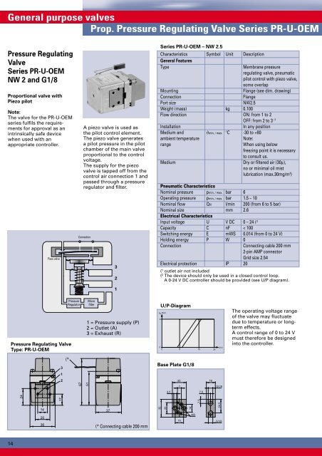
General purpose valvesProp. Pressure Regulating Valve Series PR-U-OEMPressure RegulatingValveSeries PR-U-OEMNW 2 and G1/8Proportional valve with<strong>Piezo</strong> pilotNote:The valve for the PR-U-OEMseries fulfils the requirementsfor approval as anintrinsically safe devicewhen used with anappropriate controller.<strong>Piezo</strong> valveA piezo valve is used asthe pilot control element.The piezo valve generatesa pilot pressure in the pilotchamber of the main valveproportional to the controlvoltage.The supply for the piezovalve is tapped off from thecontrol air connection 1 andpassed through a pressureregulator and filter.Connection321Series PR-U-OEM – NW 2.5Characteristics Symbol Unit DescriptionGeneral FeaturesTypeMembrane pressureregulating valve, pneumaticpilot control with piezo valve,some overlapMountingFlange (see dim. drawing)ConnectionFlangePort sizeNW2.5Weight (mass) kg 0.100Flow direction ON: from 1 to 2OFF: from 2 to 3 (1InstallationIn any positionMedium and ϑmin. / max. °C -30 to +80ambient temperaturerangeNote:When using belowfreezing point it is necessaryto consult us.Medium Dry or filtered air (30µ),no or minimal oil mistlubrication (max.30mg/m 3 )Pneumatic CharacteristicsNominal pressure pmin. / max. bar 6Operating pressure pmin. / max. bar 1.5 – 10Nominal flow QN l/min 200 (from 6 to 5 bar)Nominal size mm 2.6Electrical CharacteristicsInput voltage U V DC 0 – 24 ( 3Capacity C nF < 100Switching energy E mWS 0.014 (from 0 to 24 V)Holding energy P W 0ConnectionConnecting cable 200 mm2-pin AMP connectorGrid size 2.54Electrical protection IP 20( 1 outlet air not included( 2 The device should only be used in a closed control loop.A 0-24 V DC controller should be provided (see U/P diagram).Pressure Regulating ValveType: PR-U-OEMPressureRegulatorMicrofilter1 = Pressure supply (P)2 = Outlet (A)3 = Exhaust (R)U/P-Diagramp 2(bar)800 8 18 24U(V)The operating voltage rangeof the valve may fluctuatedue to temperature or longtermeffects.A control range of 0 to 24 Vmust therefore be designedinto the controller.3(*Base Plate G1/8122516677G1/84,57,57,551172414203637(* Connecting cable 200 mm32201514M324,5G1/814