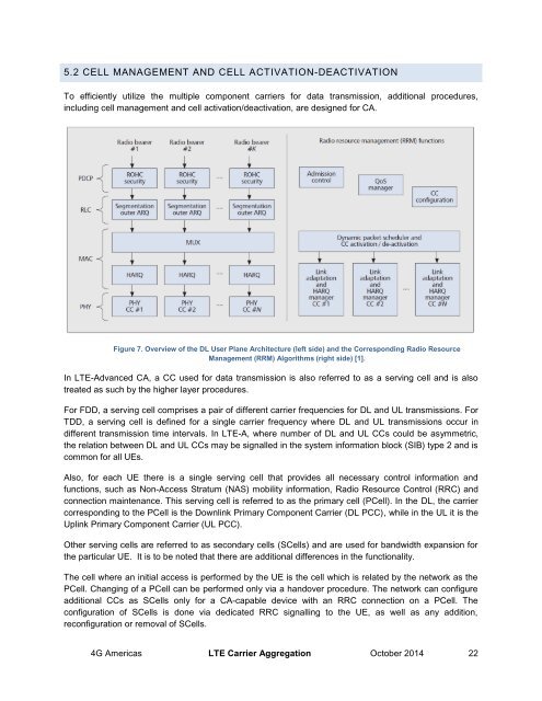
5.2 CELL MANAGEMENT AND CELL ACTIVATION-DEACTIVATIONTo efficiently utilize the multiple component carriers for data transmission, additional procedures,including cell management and cell activation/deactivation, are designed for CA.Figure 7. Overview of the DL User Plane Architecture (left side) and the Corresponding Radio ResourceManagement (RRM) Algorithms (right side) [1].In LTE-Advanced CA, a CC used for data transmission is also referred to as a serving cell and is alsotreated as such by the higher layer procedures.For FDD, a serving cell comprises a pair of different carrier frequencies for DL and UL transmissions. ForTDD, a serving cell is defined for a single carrier frequency where DL and UL transmissions occur indifferent transmission time intervals. In LTE-A, where number of DL and UL CCs could be asymmetric,the relation between DL and UL CCs may be signalled in the system information block (SIB) type 2 and iscommon for all UEs.Also, for each UE there is a single serving cell that provides all necessary control information andfunctions, such as Non-Access Stratum (NAS) mobility information, Radio Resource Control (RRC) andconnection maintenance. This serving cell is referred to as the primary cell (PCell). In the DL, the carriercorresponding to the PCell is the Downlink Primary Component <strong>Carrier</strong> (DL PCC), while in the UL it is theUplink Primary Component <strong>Carrier</strong> (UL PCC).Other serving cells are referred to as secondary cells (SCells) and are used for bandwidth expansion forthe particular UE. It is to be noted that there are additional differences in the functionality.The cell where an initial access is performed by the UE is the cell which is related by the network as thePCell. Changing of a PCell can be performed only via a handover procedure. The network can configureadditional CCs as SCells only for a CA-capable device with an RRC connection on a PCell. Theconfiguration of SCells is done via dedicated RRC signalling to the UE, as well as any addition,reconfiguration or removal of SCells.<strong>4G</strong> <strong>Americas</strong> LTE <strong>Carrier</strong> <strong>Aggregation</strong> October 2014 22
CA offers a cell activation/deactivation mechanism for configured SCells to optimize and reduce UEpower consumption. Activating/deactivating of a SCell refers to activating/deactivating the CC of the Scell,while activation of an SCell means applying normal SCell operation, which are detailed in [7]. For adeactivated SCell, as detailed in TS36.321 Rel-11, the UE does not transmit SRS 2 on the SCell, does notreport CQI/PMI/RI/PTI 3 for the Scell, does not transmit on UL-SCH 4 or on RACH 5 on the Scell and doesnot monitor the PUCCH on the Scell nor for the Scell.The activation/deactivation of the SCells is performed by the network independently for each of the SCellsserving the UE, according to internal algorithms of the network (aiming, for example to meet the UE’scurrent traffic demand). The configured SCells are initially deactivated upon addition and after ahandover.Activation is done via a dedicated Medium Access Control (MAC) control element signalling, whiledeactivation can be done either via the same dedicated MAC control element (sets differently) signallingor according to a dedicated timer maintained by the UE and the network for each Scell. The Pcell is activefor a UE in RRC connected mode and it cannot be deactivated.5.3 CA SCHEDULINGThe 3GPP has defined two main alternatives for CA scheduling: either resources are scheduled on thesame carrier on which the scheduling grant (over PDCHH) 6 is received, or resources are scheduled on adifferent carrier than the carrier on which scheduling grant is received.For the first alternative, the PDCCH is separately coded for each CC that serves the UE (PCell and scells)and reuses Rel-8/9 PDCCH structure including Rel-8/9 DCI 7 formats.For the second alternative, a single PDCCH available at the Pcell assigns resources for all CC’s of theUE. The second option is referred as a cross-carrier scheduling, and its main use case is forheterogeneous networks (further information is available in Section 6.4). To implement this method, a 32 SRS refers to Sounding Reference Signals, which are transmitted on the UL containing a known sequence to both network anddevices and allow the network to estimate the quality of the channel at different frequencies. SRS may be transmittedperiodically in a wider bandwidth (beyond the UL resources blocks allocated for UL data transmission) and also when there isno UL data transmission, so the channel information obtained from SRS is a good input to the UL scheduler at the eNB.3 CQI is Channel Quality Indicator. PMI stands for Pre-coding Matrix Indicator and RI is Rank Indicator.These three values are computed on the fly in LTE systems and used to try to optimize resource allocation among the various UEsthat are requesting service. The CQI is reported by UE to eNB. UE indicates modulation scheme and coding scheme to eNB ,that would allow it to demodulate and decode the transmitted DL data with a maximum block error rate of 10 percent. The CQIreporting can be based on PMI and RI.For PMI, the UE indicates to eNB which precoding matrix from a predefined codebook should be used for DL transmission by theeNB, which is determined by RI.For RI the UE indicates to eNB, the number of spatial layers that should be used for downlink transmission to the UE.PTI stands for precoding type indicator and it is a new feedback indicator added for LTE-Advanced, which is reported by the UE and allowsdistinguish slow from fast fading environments.4 UL-SCH is a MAC uplink transport channel and is carried over the Physical Uplink Shared Channel. The UL-SCH is used for ULtransmission of UE according to scheduling guidelines given by the eNB.5 RACH – Random Access Channel. This channel is used for the execution of the Random Access Procedure in which the network(eNB) for the first time knows that some UE is trying to get access.6 PDCCH stands for physical downlink control channel, which carries the layer one control.7 DCI stands for Downlink scheduling Control Information and is transmitted through the Physical Downlink Control Channel(PDCCH) to support the transmission of the DL and UL transport channels for UEs associated with the eNB. DCI contains theresource allocation (MCS, assignment of resorce block), TPC commands, HARQ information and MIMO precedinginformation.<strong>4G</strong> <strong>Americas</strong> LTE <strong>Carrier</strong> <strong>Aggregation</strong> October 2014 23