

4G Americas Carrier Aggregation_FINALv1 0 (2)
4G Americas Carrier Aggregation_FINALv1 0 (2)
4G Americas Carrier Aggregation_FINALv1 0 (2)

You also want an ePaper? Increase the reach of your titles
YUMPU automatically turns print PDFs into web optimized ePapers that Google loves.
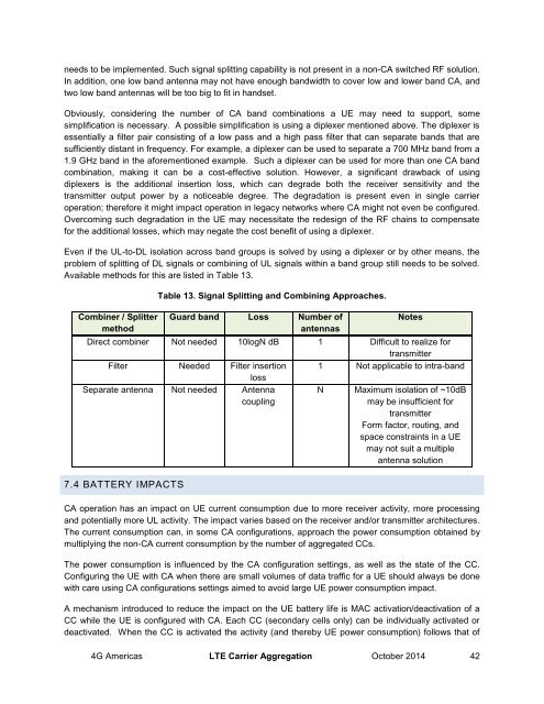
needs to be implemented. Such signal splitting capability is not present in a non-CA switched RF solution.In addition, one low band antenna may not have enough bandwidth to cover low and lower band CA, andtwo low band antennas will be too big to fit in handset.Obviously, considering the number of CA band combinations a UE may need to support, somesimplification is necessary. A possible simplification is using a diplexer mentioned above. The diplexer isessentially a filter pair consisting of a low pass and a high pass filter that can separate bands that aresufficiently distant in frequency. For example, a diplexer can be used to separate a 700 MHz band from a1.9 GHz band in the aforementioned example. Such a diplexer can be used for more than one CA bandcombination, making it can be a cost-effective solution. However, a significant drawback of usingdiplexers is the additional insertion loss, which can degrade both the receiver sensitivity and thetransmitter output power by a noticeable degree. The degradation is present even in single carrieroperation; therefore it might impact operation in legacy networks where CA might not even be configured.Overcoming such degradation in the UE may necessitate the redesign of the RF chains to compensatefor the additional losses, which may negate the cost benefit of using a diplexer.Even if the UL-to-DL isolation across band groups is solved by using a diplexer or by other means, theproblem of splitting of DL signals or combining of UL signals within a band group still needs to be solved.Available methods for this are listed in Table 13.Combiner / SplittermethodTable 13. Signal Splitting and Combining Approaches.Guard band Loss Number ofantennasNotesDirect combiner Not needed 10logN dB 1 Difficult to realize fortransmitterFilter Needed Filter insertion 1 Not applicable to intra-bandlossSeparate antenna Not needed AntennacouplingN Maximum isolation of ~10dBmay be insufficient fortransmitterForm factor, routing, andspace constraints in a UEmay not suit a multipleantenna solution7.4 BATTERY IMPACTSCA operation has an impact on UE current consumption due to more receiver activity, more processingand potentially more UL activity. The impact varies based on the receiver and/or transmitter architectures.The current consumption can, in some CA configurations, approach the power consumption obtained bymultiplying the non-CA current consumption by the number of aggregated CCs.The power consumption is influenced by the CA configuration settings, as well as the state of the CC.Configuring the UE with CA when there are small volumes of data traffic for a UE should always be donewith care using CA configurations settings aimed to avoid large UE power consumption impact.A mechanism introduced to reduce the impact on the UE battery life is MAC activation/deactivation of aCC while the UE is configured with CA. Each CC (secondary cells only) can be individually activated ordeactivated. When the CC is activated the activity (and thereby UE power consumption) follows that of<strong>4G</strong> <strong>Americas</strong> LTE <strong>Carrier</strong> <strong>Aggregation</strong> October 2014 42