Operating Manual Pelletronic V 2.21 MEco - Maine Energy Systems
Operating Manual Pelletronic V 2.21 MEco - Maine Energy Systems
Operating Manual Pelletronic V 2.21 MEco - Maine Energy Systems
Create successful ePaper yourself
Turn your PDF publications into a flip-book with our unique Google optimized e-Paper software.
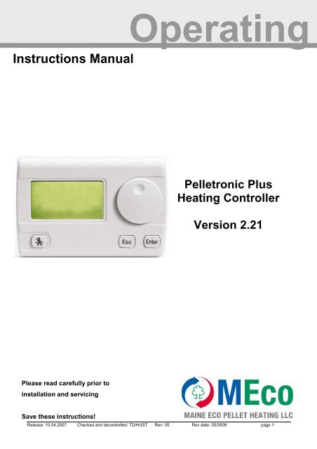
<strong>Operating</strong>Instructions <strong>Manual</strong><strong>Pelletronic</strong> PlusHeating ControllerVersion <strong>2.21</strong>Please read carefully prior toinstallation and servicingSave these instructions!Release: 10.04.2007 Checked and decontrolled: TD/HUST Rev: 05 Rev date: 05/2009 page 1
<strong>Operating</strong> Instruction <strong>Pelletronic</strong> Plus ………E 1247 USTitle: <strong>Operating</strong> Instructions <strong>Manual</strong> V 2.01Item number:USANumber of version: 01.01Version valid from: 08/2009Release:Stefan OrtnerAuthor:<strong>Maine</strong> Eco Pellet Heating LLC8 Airport RoadBethel, <strong>Maine</strong> 04217USAoffice@me-pelletheating.comwww.meco-pelletheating.comRelease: 10.04.2007 Checked and decontrolled: TD/HUST Rev: 05 Rev date: 05/2009 page 2
<strong>Operating</strong> Instruction <strong>Pelletronic</strong> Plus ………E 1247 USCONTENTSA. SAFETY WARNINGS ..................................................................................................................... 61. TYPES OF SAFETY WARNINGS ..................................................................................................................... 6B. COMPLIANCE AND CERTIFICATION .......................................................................................... 71. INTENDED USE ............................................................................................................................................ 72. IMPROPER USE ............................................................................................................................................ 73. EU STANDARDS .......................................................................................................................................... 7C. HEATING CONTROLLER .............................................................................................................. 8D. USER CONTROLS AND FUNCTION ............................................................................................ 91. USER CONTROL........................................................................................................................................... 92. FUNCTION................................................................................................................................................... 93. FLUE GAS TEST MODE – CHIMNEY SWEEP CONTROL .................................................................................... 9E. MENU STRUCTURE .................................................................................................................... 10F. MENU GUIDE ............................................................................................................................... 111. MAIN MENU .............................................................................................................................................. 112. MASTER OPERATING MODE ...................................................................................................................... 113. OUTSIDE TEMPERATURE ........................................................................................................................... 114. HEATING CIRCUIT ..................................................................................................................................... 124.1. HEATING CIRCUIT TIME PROGRAMME ....................................................................................................... 124.2. PARTY FUNCTION ..................................................................................................................................... 134.3. VACATION FUNCTION ............................................................................................................................... 144.4 HEATING CURVE SETTINGS ....................................................................................................................... 144.5 SCREED PROGRAMME ............................................................................................................................... 175. DOMESTIC HOT WATER (DHW) ............................................................................................................... 195.1. DHW TIME PROGRAMME .......................................................................................................................... 195.2. SENSOR ALLOCATION (COMBINATION TANKS ONLY) ................................................................................ 205.3. DHW RETURN PUMP ................................................................................................................................ 206. ACCUMULATOR ........................................................................................................................................ 207. SOLAR ...................................................................................................................................................... 217.1. SOLAR SUBMENU ...................................................................................................................................... 217.2. SOLAR ENERGY ........................................................................................................................................ 227.3 BOILER DELAY ......................................................................................................................................... 238. PELLEMATIC ............................................................................................................................................. 239. ÖKOMATIC ............................................................................................................................................... 2411. EXISTING BOILER ...................................................................................................................................... 2512. GENERAL .................................................................................................................................................. 26Release: 10.04.2007 Checked and decontrolled: TD/HUST Rev: 05 Rev date: 05/2009 page 4
<strong>Operating</strong> Instruction <strong>Pelletronic</strong> Plus ………E 1247 US12.1. LANGUAGES ............................................................................................................................................. 2612.2. DATE/TIME ............................................................................................................................................... 2612.3. CONTRAST/BRIGHTNESS .......................................................................................................................... 2612.4. MEASURING VALUES ................................................................................................................................ 2612.5. OUTPUTS .................................................................................................................................................. 2612.6. SAVING USER PARAMETERS ...................................................................................................................... 2612.7. REMOTE SERVICING .................................................................................................................................. 2713. CODE INPUT .............................................................................................................................................. 27G. START UP .................................................................................................................................... 281. LEARNING PERIPHERY .............................................................................................................................. 282. ÖKOMATIC ............................................................................................................................................... 303. RETURN TEMPERATURE INCREASE ............................................................................................................ 304. EXISTING BOILER ...................................................................................................................................... 315. SENSOR CALIBRATION .............................................................................................................................. 326. ROOM THERMOSTAT ................................................................................................................................. 337. HEATING CIRCUITS SETTINGS ................................................................................................................... 338. DOMESTIC HOT WATER SETTINGS ............................................................................................................. 359. RETURN PUMP SETTINGS........................................................................................................................... 3610. ACCUMULATOR SETTINGS ........................................................................................................................ 3711. SOLAR SETTINGS ...................................................................................................................................... 3712. SOLAR ENERGY ........................................................................................................................................ 4113. SWH BOILER DELAY ................................................................................................................................ 4214. HEAT MAIN CIRCULATION ....................................................................................................................... 4215. PELLEMATIC CMP .................................................................................................................................... 4216. PELLEMATIC SETTINGS ............................................................................................................................. 4316.1 FROST PROTECTION .................................................................................................................................. 4416.2 CASCADE FUNCTION ................................................................................................................................. 4417. GENERAL MENU ....................................................................................................................................... 5118. USB ......................................................................................................................................................... 51H. DIAGRAM OF THE ELECTRICAL CONNECTION ..................................................................... 53I. TERMS OF GUARANTEE ............................................................................................................ 59Release: 10.04.2007 Checked and decontrolled: TD/HUST Rev: 05 Rev date: 05/2009 page 5
<strong>Operating</strong> Instructions <strong>Pelletronic</strong> Plus V 2.18A. SAFETY WARNINGS1. Types of safety warningsThere are 4 categories of safety warnings:1. DangerFailure to observe Dangerwarnings may result in injury orendanger life.2. WarningFailure to observe Warningwarnings may result in personalinjury.3. CautionFailure to observe Cautionwarnings may result in injuryand/or damage property4. NoticeObservation to Notice warnings will help ensure troublefree operation of your <strong>Pelletronic</strong> Heating Controller.Release: 10.04.2007 Checked and decontrolled: TD/HUST Rev: 05 Rev date: 05/2009 page 6
<strong>Operating</strong> Instruction <strong>Pelletronic</strong> Plus ………E 1247 USB. Compliance and certification1. Intended useThe controller is for use in conjunction with a hydraulic circuit in accordance with the manufacturer’sspecifications.The device is not be used for any other purpose.2. Improper useImproper use such as changes to default settings in codelevel by non qualified personnel invalidates the guaranteeThe producer accepts no liability for damage to persons orproperty resulting from failure to observe the operatinginstructions.For property damage, because you did not follow theoperating instructions, the producer will not assumeliability.Only qualified personnel are permitted to open controlunits or work on electrical appliances.3. EU standardsThe heating controller is a modern electronic device.This device uses the latest technology and complies with applicable safety regulations.The controller complies with the following EU guidelines:73/23/EWG „Low Voltage Guidelines“89/336/EWG „EMC Guidelines“, including amendment guideline 92/31/EWGRelease: 10.04.2007 Checked and decontrolled: TD/HUST Rev: 05 Rev date: 05/2009 page 7
<strong>Operating</strong> Instruction <strong>Pelletronic</strong> Plus ………E 1247 USD. User controls and function<strong>Pelletronic</strong> functions and displays are controlled using the MENU SCROLL, ENTER and ESCAPE buttons.1. User controlMENU SCROLL Rotate this control tohighlight the required itemENTER – use this button to select the itemcurrently highlighted.ENTER key to save your setting.ESCAPEkey to exit menus and move uplevels to the standard windowBy pressing the key CHIMMNEY SWEEP youare prompted to select test mode2. Function1. MENU SCROLL:rotate for desireditem2. ENTERto select item3. MENU SCROLL:rotate for desiredsetting4. ENTERto save settings5. Use ESC toreturn to theprevious window6. ENTERto select mainmenu3. Flue gas test mode – chimney sweep controlSelect flue test mode by pressing the chimney sweep (not fitted to wall mounted master controllers)To proceed confirm with yes.The chimney sweep function sets the boiler to 158°F and allows up to 30minutes of continuous output for flue gas testing.Release: 10.04.2007 Checked and decontrolled: TD/HUST Rev: 05 Rev date: 05/2009 page 9
<strong>Operating</strong> Instruction <strong>Pelletronic</strong> Plus ………E 1247 USE. MENU STRUCTUREThe menu structure shows the menu levels and their functions:Start MenuMain MenuSubmenuOpeningwindowMain MenuMain plantoperating modeOutsidetemperatureHeatingcircuits 1/2Domestic hotwaterAccumulatorSolarPellematicTime programmeParty functionVacation timeHeating curve/heating limitsScreedprogrammeTime programmeSensor allocationReturn pumpSolar circuitÖkomaticSolar <strong>Energy</strong>Return watertemp. controlExisting boilerGeneralCode inputBoiler delayCMP/Boilercontrol unitLanguagesDate/TimeContrast/BrightnessMeasuringValuesOutputsServicingattitudes chargeRemote servicingRelease: 10.04.2007 Checked and decontrolled: TD/HUST Rev: 05 Rev date: 05/2009 page 10
<strong>Operating</strong> Instruction <strong>Pelletronic</strong> Plus ………E 1247 US4. Heating circuitHeating circuit(s) operationOFFAUTOHEATINGSET BACKMANUALFrost protection onlyTimed heating on. Set back during non time periodsHeating onHeating on set back temperature continuouslyBoiler is called, heating pumps run, mixing valves disconnectedWill operate when the outside temperature is below summerlimit and maximum flow temperature is not exceeded.The heating timed periods can be adjusted in thesubmenu heating circuit.Set room temperatureAdjust your room temperature.Set back temperatureAdjust the set back temperature.Set back temperature is the temperature during non timed periods.The operating mode of the heating circuits can only be changed if the plantoperating mode is set to AUTO and no analogue remote control is attached. Theadjusted heating limits and max. flow temperatures apply to all operating modes.4.1. Heating circuit time programmeThe individual items on the sub menu of the heating circuit are selected in thesame way as the main menu.Each heating circuit has 2 optional time programmes.They allow set 2 different time programmes.Only one time programme can be active at a time.Release: 10.04.2007 Checked and decontrolled: TD/HUST Rev: 05 Rev date: 05/2009 page 12
<strong>Operating</strong> Instruction <strong>Pelletronic</strong> Plus ………E 1247 USSet the days:There are the blocks Mon-Fri and Sat-Sun and individual days Mon, Tue, …Only 1 time programme may be active at a time. In each individual time programme there are theblocks “Mon-Fri “and “Sat-Sun “. When heating times are set in these blocks, they are repeated foreach of the days in the block. However individual days can then be modified as required.The lines over and/or under the individual days show whether the selected heating times on theindividual days are identical to the pertinent block. Thus if the heating times e.g. on Wednesday arechanged the line disappears over the Wednesday.Example:Wednesday:Other days time programme as Monday – FridaySelect the programme days by highlighting and pressing EnterAdjust the time limits:Set times for when you want the heating on, the rest of the time the heating will be on set back.3 heating time periods can be selected for any given day.Heating times with 1 timed periodHeating times with 2 timed periodsHeating times with 3 timed periods4.2. Party functionUse the Party function to extend the heating timeof the selected heating circuit for a single occasion.The duration of the extension can be chosen - in this case until 02:30am. Once expired, the functionbecomes inactive again. The heating control returns to programmed settings.Release: 10.04.2007 Checked and decontrolled: TD/HUST Rev: 05 Rev date: 05/2009 page 13
<strong>Operating</strong> Instruction <strong>Pelletronic</strong> Plus ………E 1247 USRoom sensor control:In effect this function controls the degree of influence that a given setting on the room thermostat hason the flow temperature to the heating system. Particularly useful in draughty buildings or where thereis high passive solar gain.0 = off Analog room thermostat or the digital remote control are off.1 - 10 = on Changing the room sensor control parameter from 0 to 1 allows the remote roomthermostat to become active. This can adjust the set temperature by ± 9°F.This indicates, how many degrees the flow temperature is raised or lowered to reachthe set room temperatureExample:Set room temperature = 68°FActual room temperature = 66°F the temperature dif ference is 2°FRoom sensor control = 3Flow temperature increase = Room sensor control x Temperature difference6° = 3 x 2Room temperature hysteresisOnly works when an analog room thermostat or a digital remote controller isinstalled and turned on.When the room temperature plus hysteresis is reached, the relevant heating pump is stopped. Theheating pump starts again when the room temperature is 1.8°F below the set room temperature.Release: 10.04.2007 Checked and decontrolled: TD/HUST Rev: 05 Rev date: 05/2009 page 15
<strong>Operating</strong> Instruction <strong>Pelletronic</strong> Plus ………E 1247 USBecause of the building’s thermal inertia, it is recommended to perform no morethan one adjustment step per day.Adjustment heating curve and base point:DaytimeRoom temperatureoutside tempToo warmToo cold41 to 59°F Decrease heating curving value by0.2 andIncrease heating curving value by0.2 anddecrease base point value by 8° increase base point value by 8°-4 to 41°F decrease heating curve value by 0.2 incr ease heating curve value by 0.2Release: 10.04.2007 Checked and decontrolled: TD/HUST Rev: 05 Rev date: 05/2009 page 16
<strong>Operating</strong> Instruction <strong>Pelletronic</strong> Plus ………E 1247 US4.5 Screed programmeOperation with incorrect settings may cause damage!Consult the floor supplier.Only use this programme in conjunction with a pump interlockswitch positioned on the flow from pump to under floor centralheating – this must be set to the max. safe temp. for theconditions of the floor.No liability is accepted by the <strong>Pelletronic</strong> supplier for damageto floors or sub floors.Continuous power supply is required to the controller tomaintain the settings for this programme.Only use programme temperatures approved byThe screed programme may be operated up to 31 days. A desired flow temperature must be adjustedfor each individual day. These temperatures are constant and not dependent on outside temp or roomthermostat settings. The function is switched off automatically at the end of the program and theheating circuit reverts to the previous operating mode.Setting the days and flow temperatures:Number of heating days, maximum 31 daysScroll days backScroll days forwardRelease: 10.04.2007 Checked and decontrolled: TD/HUST Rev: 05 Rev date: 05/2009 page 17
<strong>Operating</strong> Instruction <strong>Pelletronic</strong> Plus ………E 1247 USDesired flow temperatureActivate/deactivate screed programmeBack tomain menuRelease: 10.04.2007 Checked and decontrolled: TD/HUST Rev: 05 Rev date: 05/2009 page 18
<strong>Operating</strong> Instruction <strong>Pelletronic</strong> Plus ………E 1247 US5. Domestic Hot water (DHW)<strong>Operating</strong> mode:ONDomestic hot water heated continuously to the set point.OFFSet water temperature is reduced to 8° for frost p rotection.AUTO Domestic hot water will be heated to the set temperature during time periods.The operating mode of DHW can only be changed, if the operating mode plant is set to AUTO or DHW.Boost:If boost is On, domestic hot water heated to the set point on a singleoccasion.Water temperature:Set the water temperature.Water temperature min.:Set the minimum water temperature.Minimum water temperature is on outside time period and when thedomestic hot water is set to Auto or DHW5.1. DHW time programmeSetting DHW time programme is the same as setting heating circuit time programme.The domestic hot water time programme works the same way like the heating circuit time programme.See page 12 Heating circuit time programmeRelease: 10.04.2007 Checked and decontrolled: TD/HUST Rev: 05 Rev date: 05/2009 page 19
<strong>Operating</strong> Instruction <strong>Pelletronic</strong> Plus ………E 1247 US5.2. Sensor allocation (combination tanks only)The switch off sensor is only shown, if combination tank is fitted and selected in the <strong>Pelletronic</strong> menu!This function allows allocation of the sensor used for determining DHW set point (TPO [upper sensor],TPM [middle sensor], TPU lower sensor)It is important to install the DHW sensor to the I/O Box in order to activate the DHW programme.When the combination tank programme is selected, you can allocate the sensors.Do not use TPO as switch off sensor, the TPO can only bea switch on sensor!DHW, TPM and TPU can be used as switch on and switch off sensors.TPU is normally used as solar return sensor. If the DHW sensor is selected, use the hysteresis tochange the temperature difference on the selected switch off sensor.5.3. DHW Return pumpThe return pump circulates the domestic hot water, when a secondary return is fitted.When this function is switched on you can see and set the time programme.<strong>Operating</strong> mode:ON temperature:Choose between AUTO and OFF.The point at which the pump starts.Is the domestic hot water temperature below the settled ON temperature,the return pump is off.Time programmes: Select a time programme and set it. See also page 126. AccumulatorAccumulator information onlyDisplay of actual temperatures:TPO: AC upper temperature of upper sensorTPM: AC middle temperature of middle sensorRelease: 10.04.2007 Checked and decontrolled: TD/HUST Rev: 05 Rev date: 05/2009 page 20
<strong>Operating</strong> Instruction <strong>Pelletronic</strong> Plus ………E 1247 US7. Solar7.1. Solar submenu<strong>Operating</strong> mode:ONSolar system is onOFFSolar system is off.Coll temp Displays actual collector temperatureTPU: Displays actual DHW temperatureThe solar system can be switched on/off irrespective of the plant mode.The operation mode SOLAR can also be changed, if the OPERATING MODEPLANT is set on OFF!Very high domestic hot water storage temperatures arepossible!Solar pump switch ON:Solar pump switch OFF:TPU max:TPU hyst:The difference between collector and Solar return (TPU) is greater thanthe set temperature.The difference between collector and Solar return (TPU) is less thanthe set temperature.The solar pump is switched off, when the DHW set point is reached.The solar pump is switched on again, when the temperature of DHWfalls below set point minus the hysteresis.The TPU hysteresis prevents the solar pump cycling.Release: 10.04.2007 Checked and decontrolled: TD/HUST Rev: 05 Rev date: 05/2009 page 21
<strong>Operating</strong> Instruction <strong>Pelletronic</strong> Plus ………E 1247 USCollector smoothing:It only functions on solar circuit one, it can be switched on and off and itensures an efficient delivery of energy from the collectors.Collector smoothing can only be set, when the speedcontrol function is on in the code protected parameters.Collector temp min/Control rangeAt this temperature the solar pump starts to run at minimum speed.The pump speed increases within the set range as the collectortemperature increases.7.2. Solar energyThis function measures the yield of the solar systemDisplays current energy and logs previous days.For the function solar energy it is necessary to install:Pulse volume meter, temperature sensor and return temperature sensor:We recommend consulting your specialist installer before changing these settingsCurrent (kW): Display of the current solar energy (refreshes every 60 sec)Today (kWh): Display of today’s solar energy since 00:00.Yesterday (kWh): Display of the of yesterdays solar energyTotal (kWh):Display of the solar energy since the last set dateFlow rate (l/min): Refreshes every 60 sec.Flow temp (°F): Display of the current flow temperatureReturn (°F):Display of the current return temperatureSolar energy:Reset:Display of the calculation of the total solar energy.Reset the total solar energy back to zero. The actual date is the new start datefor the solar log.Release: 10.04.2007 Checked and decontrolled: TD/HUST Rev: 05 Rev date: 05/2009 page 22
<strong>Operating</strong> Instruction <strong>Pelletronic</strong> Plus ………E 1247 US7.3 Boiler delayThis can only be set in the code protected parameters. The boiler delay is only possible, when the heatexchanger of the solar plant is in the accumulator. The boiler delay holds the boiler off, whenever thesolar collector is above the minimum temperature and the temperature is within the delay time.8. PellematicBoiler temp: shows the actual boiler temperatureBoiler temp set: shows the set boiler temperature, calculated to meet the highest temperaturerequirement at the time (e.g. hot water 140°F + 18 °F excessive temp.)Pellematic CMP shows the number of installed boilers (default = 0)You only see the in Learning Periphery activated boilersPellematic 01: You are in the boiler control CMP from boiler 01Display area of theboiler controlKT = Current boiler temperatureRGT = Flue gas temperature<strong>Operating</strong> state of the BoilerBy turning the Menu scroll you get to the menu of the heating controller. Press Enter to setparameters.Release: 10.04.2007 Checked and decontrolled: TD/HUST Rev: 05 Rev date: 05/2009 page 23
<strong>Operating</strong> Instruction <strong>Pelletronic</strong> Plus ………E 1247 US9. Ökomatic (Wood log boiler)Boiler temp.:Boiler temp set:shows the actual boiler temperatureshows target temperature for the boiler, calculated to meet the highesttemperature requirement at the time (e.g. hot water 140 °F + 18 °F excessivetemp.)Pellematic and Ökomatic can’t be selected at the sametime.Ökomatic Warning:A warning message appears, if there is a boiler call and the temperature ofthe Ökomatic boiler is below 113°F. The burner dema nd has no effect on theÖkomatic, only a warning is issued.The warning message clears given the following conditions:• No burner call• Boiler temperature rises by 9°F• Boiler temperature is above 113°F• ESC is pressedRelease: 10.04.2007 Checked and decontrolled: TD/HUST Rev: 05 Rev date: 05/2009 page 24
<strong>Operating</strong> Instruction <strong>Pelletronic</strong> Plus ………E 1247 US10. Return Temperature IncreaseBoiler temp: shows the actual boiler temperatureUse Return Temperature Increase only with the combinationPellematic, Thermomat and Accumulator.This function requires I/O Box E1228 heating circuit 2 of the firstI/O box must be used!If the return temperature increase is active, Pellematic is not displayed in the main menu,as in this menu are no relevant information. Pellematic will not respond to this boiler sensor,as it is in Thermomat. It only responds on the buffer sensors (TPO and TPM)11. Existing boilerIf there is an Existing boiler used in the system, the <strong>Pelletronic</strong> heatingcontroller recognizes it automatically. In this case the sensor TPO is used asboiler sensor. The TPO is displayed as Boilert Ac. When the Existing boilerreaches the ON temperature, the Pellematic turns of and the plant uses theenergy from the Existing boiler.Boiler temp: Shows the actual boiler temperature.The TPO in the Existing boiler is used as boiler sensor.The return temperature increase is not regulated by the<strong>Pelletronic</strong> Plus.Release: 10.04.2007 Checked and decontrolled: TD/HUST Rev: 05 Rev date: 05/2009 page 25
<strong>Operating</strong> Instruction <strong>Pelletronic</strong> Plus ………E 1247 US12. GeneralAccess to general system information and settings12.1. LanguagesSelect the language12.2. Date/TimeUse this setting to set the date and timeIn the case of a power failure of more than 2-3 days clocktime is lost, and parameter settings may be lost. When thepower is back, set the new date and time. There is anautomatic adjustment to seasonal time.12.3. Contrast/BrightnessAdjustment of the contrast, the brightness and the duration of the backgroundlighting12.4. Measuring valuesDisplay of all SET and ACTUAL temperatures in the plantThis provides a most useful view of the heating system status12.5. OutputsDisplay of all outputs in the plant. Allows remote verification of pump and valvesettings.Exception: Accumulator pump – controlled by the boiler12.6. Saving user parametersLoading the parameters previously saved by the service technician.If no parameters have been changed, the default values will be saved.Release: 10.04.2007 Checked and decontrolled: TD/HUST Rev: 05 Rev date: 05/2009 page 26
<strong>Operating</strong> Instruction <strong>Pelletronic</strong> Plus ………E 1247 US12.7. Remote servicingThis function is optional. The necessary additional hardware is extra availablefrom your ÖkoFEN distributor.• Please refer to operating instructions for the TC35isupplied with unit.• The remote control only is available in German and13. Code inputOnly accessible by authorizedspecialists! They can adjust furthersettings after entering the code.Release: 10.04.2007 Checked and decontrolled: TD/HUST Rev: 05 Rev date: 05/2009 page 27
<strong>Operating</strong> Instruction <strong>Pelletronic</strong> Plus ………E 1247 USG. START UPSettings in the code-protected parameters may only beadjusted by qualified personnel.The code expires automatically, on return to the main menu.By entering the code additional functions appear in the different levels of the menustructure.Plans of different hydraulic systems are available onrequest from your ÖkoFEN national distributor.1. Learning peripheryIn Learning periphery you adjust witch participants are available for the system. After Learningperiphery the heating controller displays all connected items of hardware in the main menu.Now you can make further settings. Learn periphery whenever sensors are changed or any otherconnection is changed in the I/O box.Number I/O (input/output units): number of I/O boxes is adjustable (1 – 3).Maximum of 6 heating circuits per <strong>Pelletronic</strong> heating controllerI/O-box address settingWhen using more than 1 I/O Boxes ensure that each I/OBox has its own address with No.1 for boiler and outsidesensor and at least 1 heating circuit flow temperatureRelease: 10.04.2007 Checked and decontrolled: TD/HUST Rev: 05 Rev date: 05/2009 page 28
<strong>Operating</strong> Instruction <strong>Pelletronic</strong> Plus ………E 1247 USNumber of slave units:The number of digital remote controllers must be set (0-6).Pay attention to the operation instruction of the digitalremote control. It is added to the digital remote control.Boiler type:Select Pellematic.Return temperature increase:Select NoException:Change to Yes only by using a ThermomatReturn temperature increase is to be used on the secondheating circuit of the I/O Box 1.See return temperature increase page 30If an accumulator is in the system, TPO and TPM sensorsmust be connected. TPO sensor must be fitted just belowflow pipe to pump station and TPM sensor must be fittedjust above return pipe from the pump station.If only the TPO sensor is connected, the controller detectsno accumulator. The <strong>Pelletronic</strong> interprets this as a secondboiler. After each time Learning periphery it’s necessary toreset the combination/multi storage tank setting back onBoiler sensor and Outside sensormust be connected to the first I/Ounit (Address 1)Pellematic CMP: Enter the number of Pellematic CMP (Default = 0)If there are 2, 3 or 4 Pellematic CMP, the Pellematic plugs1 to 4 have to be inserted to Input RGF 10 11 of therespective boiler control. After Learning Periphery you seeall activated Pellematics in the menu point Pellematic CMPRelease: 10.04.2007 Checked and decontrolled: TD/HUST Rev: 05 Rev date: 05/2009 page 29
<strong>Operating</strong> Instruction <strong>Pelletronic</strong> Plus ………E 1247 US2. ÖkomaticBoiler temp Max: Set the Boiler temperature maximum.When Ökomatic reaches the Boiler temp Max, all pumps start for using all theenergy from the boiler.This process stops, when the boiler temperature falls below the Boiler temp Maxminus the adjusted difference.(e.g.: BT Max. 203°F minus difference 12.6°F = 190. 4°F )Pump start: Pump start temperatureWhen the boiler temperature reaches the pump start, the pumps start to runPlants without an accumulatormay not work with a pump startbelow 60° F3. Return temperature increaseFor the Return temperature increase use the circuitheating at the 1. I/O-Box. It is connected with flow sensor2, 2 and heating circuit pump 2.Return temperature increase is only for the combinationPellematic, Thermomat and accumulator. The boiler sensorof the Pellematic will be connected to the Thermomat.Release: 10.04.2007 Checked and decontrolled: TD/HUST Rev: 05 Rev date: 05/2009 page 30
<strong>Operating</strong> Instruction <strong>Pelletronic</strong> Plus ………E 1247 US4. Existing boilerThe menu existing boiler controls the interaction of the existing boiler and the Pellematic. When theExisting boiler reaches the ON temperature, the Pellematic turns of and the plant uses the energy fromthe Existing boiler.Existing boiler is active, if the heating controller detects only 1 accumulator sensor TPO, seeLearning periphery page 28. The TPO has to be connected with the I/O Box 1. There cannot be anaccumulator, because the sensor TPO is used as boiler sensor for the existing boiler.When the Existing boiler reaches the On temperature of the valve inversion, alsowhen there is no demand for the boiler, the DHW will be heated and afterwards theheating circuits.The function existing boiler is only used for log boilersand it cannot include an accumulator.Release: 10.04.2007 Checked and decontrolled: TD/HUST Rev: 05 Rev date: 05/2009 page 31
<strong>Operating</strong> Instruction <strong>Pelletronic</strong> Plus ………E 1247 USDiverter valve ON: The start temperature of the diverter valve.The diverter valve is connected to the spare outputWhen the diverter valve is switched to the existing boiler, the Pellematic isshut down!Diverter valve hysteresis: Prevents cycling of the diverter valve.e.g.: With a diverter valve start temp 140° F and a hysteresis of 3.6° K, thediverter let switches with 136.4 °F.Diverter Valve inversion: This allows inversion of the switching of the valve to accommodate anexisting diverter valve.Pellematic delay: When the temperature of the existing boiler falls below the start temp, onlyafter expiring the off time will be a new demand to the Pellematic.Pump start:When the existing boiler reaches this temperature, the DHW and Heatingcircuit pumps start.The maximum temperature for both boilers can be set!Return temperature increase of the existing boiler, isnot controlled by the heating controller <strong>Pelletronic</strong> Plus.5. Sensor calibrationThis function allows the displayed value of each sensor to be calibrated for + or – 9°F. This may benecessary with long lengths of the cable.Only sensors found during Learning periphery are displayed.Release: 10.04.2007 Checked and decontrolled: TD/HUST Rev: 05 Rev date: 05/2009 page 32
<strong>Operating</strong> Instruction <strong>Pelletronic</strong> Plus ………E 1247 US6. Room thermostatThe room thermostat measures the room temperature and compares it with the set room temperature.The flow temperature will be adjusted, depending on the room sensor control.(See room sensor control p. 15)Assignment: Assign the room thermostat to the right heating circuit.Room sensor: Activate the room thermostat of the controller for wall fasteningThe room senor can only be assigned to a heating circuit without a sensor!7. Heating circuits settingsMax Flow temperature:Sets the maximum flow temperature to the selected heating circuit.This should not be used as the only protection againstover temperature to the heat circuit.Min Flow temperature:Sets the minimum flow temperature to the selected heating circuit.The flow temperature will not fall below this pointirrespective of other controller settings.Temperature increase:(System heat loss adjustment)Sets the boiler or accumulator temperature above the set flowtemperature of the circuit calling for the highest temperature.E.g.: Set at 9°F with a heating/DHW circuit with a set temperature of140°F the minimum boiler / accumulator temperature will be set to149°F. The boiler is not called when boiler/accumul ator is above theminimum temperature.Release: 10.04.2007 Checked and decontrolled: TD/HUST Rev: 05 Rev date: 05/2009 page 33
<strong>Operating</strong> Instruction <strong>Pelletronic</strong> Plus ………E 1247 USMixer Yes/No:Mixer time open:Mixer time rest:Mixer time close:Select type of valve used to control heating circuits.There are heating circuit with mixer motor or direct heating circuitopening time of the mixerrest time between open and close of the mixerclosing time of the mixerBoiler load range:The mixer opening speed increases with boiler temperature in the set range.Flow range:This function dynamically reduces the rate at which the mixer operates to reduce boiler cycling,particularly useful when starting systems with high load.Mixer operating time:Adjusts the time the mixer opens or closes completely.Release: 10.04.2007 Checked and decontrolled: TD/HUST Rev: 05 Rev date: 05/2009 page 34
<strong>Operating</strong> Instruction <strong>Pelletronic</strong> Plus ………E 1247 USBoiler temperature smoothing:The boiler temperature smoothing controls the boiler load by smoothing the operation of the mixer.This function operates, when the boiler temp fails to rise above the boiler temp min plus the boiler temprise, this function influences the mixer, therefore helping to maintain the boiler temperature.The boiler temperature smoothing operates only on systems without accumulator.Boiler load control range:Minimum Temp/Rise time:Is the temperature range within the <strong>Pelletronic</strong> measures.This is the minimum temperature rise required over the rise time8. Domestic hot water settings1 The boiler temperature rises or exceeds the minimum temperaturewithin the set rise time. The Mixer opening time is not influenced.2 The boiler temperature remains steady within the set rise time.The mixer stays in the same position.3 The boiler temperature falls within the set rise time.The mixer starts to close.4 The boiler temperature rises or exceeds the minimum temperaturewithin the set rise time. The Mixer opening time is not influenced.DHW priority:Temperature increase:The hot water priority can be switched on or off. DEFAULT is ON.Useful for combination tanks with radiator systems.When ON, the heating circuits will not run until the DHW reaches theset point. When OFF, the DHW and heating will operate in parallel.This increases the DHW set temperature.E.g. Use this function to over come heat losses in connecting pipework.Release: 10.04.2007 Checked and decontrolled: TD/HUST Rev: 05 Rev date: 05/2009 page 35
<strong>Operating</strong> Instruction <strong>Pelletronic</strong> Plus ………E 1247 USPump run on:Hysteresis:This function is set in minutes and determines the run on time of theDHW pump. This allows residual energy in the boiler or accumulator tobe transferred to the DHW cylinder.E.g. 10 min or when boiler temp is lower than DHW cylinder which everoccurs first.Maintains the temperature of the DHW within this range during a timedor manual ON period. Only functions when the operating mode of theDHW has to be on or auto. If the operating mode is set auto, there hasto be a demand for the burnerLegionella Protection:Raises DHW cylinder temperature to Legionella pasteurisationtemperature, 149°F on selected day each week.You can deactivate this function.Full pasteurisation may not be possible in some types ofcylinder due to position of boiler coil or otherconsiderations, consult relevant cylinder manufactures fordetails. Risk of Scolding from very hot water!DHW Return PumpYou can activate and deactivate the return pump. You can activate 1 returnpump or 1 booster pump per I/O box.9. Return pump settingsFunctions with a separate time programme.Rest time: pump restingRun time: pump runningRelease: 10.04.2007 Checked and decontrolled: TD/HUST Rev: 05 Rev date: 05/2009 page 36
<strong>Operating</strong> Instruction <strong>Pelletronic</strong> Plus ………E 1247 US10. Accumulator settingsThe <strong>Pelletronic</strong> heating controller detects the accumulator automatically, when sensors TPO and TPMare installed.Accumulator temperature Max:The maximum set point varies according to the highest temperature required by the controller. If thereis no demand, the accumulator is loaded to the accumulator max.This set point is measured by the middle sensor TPM (= Turn Off Sensor)Accumulator temperature Min:When the accumulator temperature falls below the minimum temperature measured by the uppersensor TPO the boiler is called to load the accumulator to the set point.Multi combination accumulator:When sensors TPO and TPM are detected by the controller when learning periphery the controllerfunction automatically switches to accumulator control.If a combination tank is installed this must be activated in accumulator settings menu.In this menu one of 4 sensors TPO, TPM, DHW and TPU may be assigned to the act as the controllingsensor for the DHW function of the combination tank. This determines the volume of DHW available.Each time learning periphery is enabled the combination tanksetting defaults to NO. The sensor assigned to DHW looses itsfunction until re-set as indicated above. The minimumrequirement is: TPO, TPM and DHW sensor11. Solar settingsSolar switch off:Select the sensor to be used for the cylinder/accumulator/combination tank set point. This switches offthe solar input to the DHW cylinder / combination tank. Only the sensors installed and found duringlearning periphery are shown in this list.Risk of Scolding from very hot water!Release: 10.04.2007 Checked and decontrolled: TD/HUST Rev: 05 Rev date: 05/2009 page 37
<strong>Operating</strong> Instruction <strong>Pelletronic</strong> Plus ………E 1247 USIf the low sensor (TPU) is selected as the set point “switch” high temperatures can occur at the top ofthe cylinder.Collector Temperature Max:When the collector reaches the collector temperature maximum, the solar pump switches off.Collector Hysteresis:This is the start temperature for the pump as the temperature of the collector falls. It prevents cyclingPump type:Choose between A category pump and standard pump.If the pump speed control is on, standard pumps can bedamaged.Speed control On/OffThe speed regulation of the solar pump can be switched on and/or off.Only functions with suitable pumps.Type of speed control:Speed control is only possible with A category pumps. You can choose between Analog and PWM.2 different types of A rated pumps: 1. Analog pumps with 0-10 V control2. PWM pumps with 24V control.For each type of pump you have to adapt the I/O BOX and the <strong>Pelletronic</strong> settings.Backside I/O-BOXJumper (Analog or PWM)Jumper position:Release: 10.04.2007 Checked and decontrolled: TD/HUST Rev: 05 Rev date: 05/2009 page 38
<strong>Operating</strong> Instruction <strong>Pelletronic</strong> Plus ………E 1247 USThe type of rotary speed regulation has to be identicalwith the position of the jumper!The jumper positions must be correct for each jumper.Solar protection is an automatic solar heat “dump”.The collector protection function can be switched on or off.The solar switch off temperature / Hysteresis protection:Solar protectionWhen enabled and the set collector temperature is reached this function the DHW and heating pumpsare switched on. When switched on and the set collector temperature is reached the DHW and heatingpumps are switched on, the heating circuit mixers are opened and excess heat from the DHW cylinder /combination tank is “dumped” via the heating system. The only restriction is the maximum flowtemperature set in each heating circuit.This function ceases when either:The collector temperature reaches the maximum collector temperature.The collector temp. falls below the protection temp. given the adjusted protection hysteresis.The temperature must be always set below, than themaximum collector temperature!Scavenging programme:By pulsing the solar pump [time programme and duration of pump pulse adjustable] high temperaturefluid in the collector is brought into contact with the collector sensor [S1]. This function is useful withdesigns of collector where there is little internal fluid convection such as tube systems with manifolds.Scavenging on temperature:Collector temperature in °F below which pump pulse programme is off. Prevents accidental operation ofthis programme at inappropriate times.Scavenging programme:Time programme can be set to prevent solar pump pulse programme running at night.Release: 10.04.2007 Checked and decontrolled: TD/HUST Rev: 05 Rev date: 05/2009 page 39
<strong>Operating</strong> Instruction <strong>Pelletronic</strong> Plus ………E 1247 USPriority PRIO 1 and PRIO 2:<strong>Systems</strong> with more than on solar hot water cylinder/combination cylinderSelect priority of solar cylinders. Allows cascade function loading of cylinders.Cylinders can be loaded in series cascade or in parallel.Solar pump pulse program for PRIO 2:Set the solar pump pulse programme for solar circuit PRIO 2Only for solar circuit PRIO 2 it is necessary to set the solar pump pulse programme.After the scavenging period of solar circuit PRIO 2 follows the scavenging interval of both solar circuits.After the scavenging interval follows the scavenging time.During the scavenging time the solar circuit checks, if there is a new demand for PRIO 1 or not.If there is a demand for solar circuit 1, the pump will run, if not the scavenging period of solar circuit 2starts. If during the scavenging period of solar circuit 2 there is a demand from solar circuit 1, it will beimmediately fulfilled.Number of solar pumps:Choose between 1 and 2:1………2 Solar circuits with 1 solar pump and 1 motorised valve2………2 Solar circuits with 2 solar pumpsConnections in the I/O Box for solar pump and motorisedvalve Solar pump ………. connect to solar pump 1Motorised valve ….. connect to solar pump 2Release: 10.04.2007 Checked and decontrolled: TD/HUST Rev: 05 Rev date: 05/2009 page 40
<strong>Operating</strong> Instruction <strong>Pelletronic</strong> Plus ………E 1247 US2 Solar circuits with 1 pump and 1 motorised valveSolar circuit1…..Priority 1Solar circuit 2….Priority 2Example of 1 solar circuit with 1 pump an d 1 motorised valve2 Solar circuits with 2 pumpsOperates as with 1 pump but both pumps in parallelMinimum temp diff:This setting is displayed only when 2 solar pumps and 2 heat exchangers are installed.If the Temperature difference between collector and accumulator (TPU) of PRIO 1 is greater than theminimum temp diff both solar circuits run.12. Solar energyLitre/impulse:Adjust the setting according for the volume meter use!Default is 1 litre for the ÖkoFEN solar yield set.Release: 10.04.2007 Checked and decontrolled: TD/HUST Rev: 05 Rev date: 05/2009 page 41
<strong>Operating</strong> Instruction <strong>Pelletronic</strong> Plus ………E 1247 US13. SWH Boiler delayDelay time:Temp diff:Temp rise:Rise time:Coll Temp min:Set the duration of the boiler delay.Set the Temp diff max between TPO and TPO setThe Min temperature rise at the TPOThe time during which the temp increase is measuredThe collector temperature minimumThe boiler delay operates when:• The operating mode of the solar circuit is on• The boiler delay is on• The maximum temperature difference is not exceeded• The Rise temp is higher than the set rise temp within the rise time• The collector temperature is higher than the collector minimum14. Heat Main CirculationThe Heat Main Circulation pumps primary water, when the boiler is separatedfrom the pump stations.Choose the number of Heat Main Circulation <strong>Systems</strong>. Maximum is 1 per I/Obox up to 3 I/O boxes.Switch on the chosen Heat Main Circulation System.In the menu item component you can assign any or all circuits to operate with the booster pump.The booster pump runs with any assigned pump.15. Pellematic CMPSee also chapter Pellematic page 23Release: 10.04.2007 Checked and decontrolled: TD/HUST Rev: 05 Rev date: 05/2009 page 42
<strong>Operating</strong> Instruction <strong>Pelletronic</strong> Plus ………E 1247 US16. Pellematic settingsBoiler increase temperatureThis calculates the boiler set point taking into account the highest user calling at the time. Ensuresthere is sufficient temperature difference between boiler and user - heating circuit/DHW for effectiveheat exchange.Example:The set hot water temperature amounts to 140°F, the increase temperature of the hot water amounts to9°F. If the boiler increase temperature amounts to 18°F, it results that the boiler temperature set po int is167°F. (DHW temp. + DHW increase temp. + boiler inc rease temp.)Minimum boiler temperatureThe minimum boiler temperature protects boiler from internal corrosion and ensures optimumcombustion conditions. Limited to 140°F when no acc umulator is installed.Maximum boiler temperatureCools the boiler, by switching on all pumps and opening mixers, when the maximum boiler temperatureis reached. This procedure stops, if either the boiler temperature falls below the maximum boilertemperature minus the set boiler increase temperature.(boiler temperature max. 203°F minus boiler increas e temp. 12.6°F = 190.4°F)Release: 10.04.2007 Checked and decontrolled: TD/HUST Rev: 05 Rev date: 05/2009 page 43
<strong>Operating</strong> Instruction <strong>Pelletronic</strong> Plus ………E 1247 USPump on temperatureThey cannot be switched on, when the boiler temperature is below the set switch on temperature.This function is for boiler corrosion protection and is not used when anaccumulator is installed.Pump temperature min for systems without accumulator tank is 140°F, pro tects boiler from internalcorrosion and ensures optimum combustion conditions.16.1 Frost protectionTemperature limit:The frost protection becomes active, if the outside temperature falls below the set temperature (default39°F). When the outside temperature falls below, th e mixers are opened and the system is flushed bythe pumps every 55 minutes for 5 minutes.If any internal sensor falls below 46°F, then the b oiler is called. This limit is adjustable from -4 to 39°F.This function doesn’t protect against frost damage!Frost protection rest time and running time:Within this interval the pumps were not headed for other reasons, then these are switched on for oneperiod (the freeze protection - running time) and the mixers are opened.16.2 Cascade functionNumber of boilers:If the Pellematic CMP is 1 or more, the number of boilers is adapted automatically.If the number of Pellematic CMP is 0 you can adapt it here.If the number of Pellematic CMP is between 1 and 4, the number can’t be adapted here.The number of Pellematic CMP you find in Learning Periphery, page 28.Hysteresis 1, 2 and 3:Avoid the clocking of the boiler by setting ON and OFF temperatures.Release: 10.04.2007 Checked and decontrolled: TD/HUST Rev: 05 Rev date: 05/2009 page 44
<strong>Operating</strong> Instruction <strong>Pelletronic</strong> Plus ………E 1247 USBoiler duty: It always starts with the lead boiler. Each boiler runs for the same period of time. But thesequence of operation changes to ensure equal running time for each boiler.The boiler duty is the operating time of each boiler.If the setting of the boiler duty is 0, then always boiler number 1 starts.Off temperature:When the outside temperature is higher than the off temperature, no requirement is issued to theseboilers: Boiler 2…………. cascade with two boilersBoiler 2 and 3…. cascade with three boilersBoiler 3 and 4….. cascade with four boilersTo get to the menu points Reserve Boiler and DelayTime, the number of boilers has to be at least 2.Reserve Boiler:It is possible to connect a reserve boiler which is excluded from the duty cycle.It is only used for the coverage of maximum demand of energy.Delay time:It ensures that number 2 and subsequent boilers start in sequence and only when the load demands.Description of the function of the four possibilities of cascadesBoiler 1………I/O BOX 1 burner contactBoiler 2………I/O BOX 1 reserve outputBoiler 3………I/O BOX 2 burner contactBoiler 4………I/O BOX 2 reserve outputInstall an additional relay at the reserve output.See the manual: “Additional relay for plants of several boilers <strong>Pelletronic</strong>Plus number of the part E1259“Only 1 boiler sensor is needed in the cascade system. Thismust be positioned where a common flow temperature canbe measured and connected to I/O box 1Release: 10.04.2007 Checked and decontrolled: TD/HUST Rev: 05 Rev date: 05/2009 page 45
<strong>Operating</strong> Instruction <strong>Pelletronic</strong> Plus ………E 1247 US2 Cascade without accumulator2 Cascade with accumulatorRelease: 10.04.2007 Checked and decontrolled: TD/HUST Rev: 05 Rev date: 05/2009 page 46
<strong>Operating</strong> Instruction <strong>Pelletronic</strong> Plus ………E 1247 US3 Cascade without accumulatorRelease: 10.04.2007 Checked and decontrolled: TD/HUST Rev: 05 Rev date: 05/2009 page 47
<strong>Operating</strong> Instruction <strong>Pelletronic</strong> Plus ………E 1247 US3 Cascade with accumulatorRelease: 10.04.2007 Checked and decontrolled: TD/HUST Rev: 05 Rev date: 05/2009 page 48
<strong>Operating</strong> Instruction <strong>Pelletronic</strong> Plus ………E 1247 US4 Cascade without accumulatorRelease: 10.04.2007 Checked and decontrolled: TD/HUST Rev: 05 Rev date: 05/2009 page 49
<strong>Operating</strong> Instruction <strong>Pelletronic</strong> Plus ………E 1247 US4 Cascade with accumulatorRelease: 10.04.2007 Checked and decontrolled: TD/HUST Rev: 05 Rev date: 05/2009 page 50
<strong>Operating</strong> Instruction <strong>Pelletronic</strong> Plus ………E 1247 US17. General menuLoading all parametersAll previously saved parameters may be loaded from the internal memory.Saving all parametersAll parameters are saved.Log-FileAll attempted and successful code inputs are logged.Logs access to code level18. USBThere are 4 USB functions, when a USB Stick is connected to the <strong>Pelletronic</strong>:• Save Settings: saves all parameters prior to updating software. Data is saved in a named file.• Load Settings: loads the saved settings after the software update.Select the right file by moving the arrows right or left• Save all data: logs all heating controller activity, excludes mixer activityRelease: 10.04.2007 Checked and decontrolled: TD/HUST Rev: 05 Rev date: 05/2009 page 51
<strong>Operating</strong> Instruction <strong>Pelletronic</strong> Plus ………E 1247 US• Software updateYou can load software from a USB stick.Preconditions:• The controller must have a USB port.• Only version 2.18 or higher may be used.Save individual settings beforeperforming software update.Operational sequence:1. Disconnect the heating controller from the power supply.2. Remove controller from the fastener, the USB port is on the underside of the controller pc board3. Plug in the USB stick.4. Reconnect the heating controller to the power supply. The heating controller startsautomatically.5. There are 2 options:Stop the process with Esc ORconfirm the update with Enter.After confirming with Enter the software update runs automatically.For a successful software updateyou mustn’t interrupt the process(Esc)6. When the update is complete, the display shows:”Program download complete”7. Unplug the USB stick and restart deviceDisconnect the USB-Stick.Refit and restart the heating controller.Release: 10.04.2007 Checked and decontrolled: TD/HUST Rev: 05 Rev date: 05/2009 page 52
<strong>Operating</strong> Instruction <strong>Pelletronic</strong> Plus ………E 1247 USH. Diagram of the electrical connection<strong>Pelletronic</strong> Plus I/O – Box and PellematicRelease: 10.04.2007 Checked and decontrolled: TD/HUST Rev: 05 Rev date: 05/2009 page 53
<strong>Operating</strong> Instruction <strong>Pelletronic</strong> Plus ………E 1247 USRelease: 10.04.2007 Checked and decontrolled: TD/HUST Rev: 05 Rev date: 05/2009 page 54
<strong>Operating</strong> Instruction <strong>Pelletronic</strong> Plus ………E 1247 USCable specificationOutput Units see the Connecting diagram at the front sideFunction Pin name I/O BOX Type of cable Width MaxHC pump 1 O1 YML-J 3x0.75 2AHC pump 2 O2 YML-J 3x0.75 2ADHC pump O3 YML-J 3x0.75 2AMixer HC1 open O4 YML-J 3x0.75 2AMixer HC1 close O5 YML-J 3x0.75 2AMixer HC2 open O6 YML-J 3x0.75 2AMixer HC2 close O7 YML-J 3x0.75 2AReserve O8 YML-J 3x0.75 2ACirculation/booster pumpO9 YML-J 3x0.75 2ASolar pump 2 O10 YML-J 3x0.75 2ASolar pump 1 TR YML-J 3x0.75 2ABurner contact C / NO YML 2x0.75 xBus cable RS485 A / B / 24V / GND LS-YYCVY-0Z 4x0.75 xOutput speed control SO1 OUT1 YML 2x0.75 xmax pro I/O BOX 6,5AInput Units see the Connecting diagram at the front sideFunction Pin name I/O BOX Type of cable Width Type of sensorRemote control HC 2 I2 LS-YYCVY-0Z 4x0.75 xRemote control HC 1 I1 LS-YYCVY-0Z 4x0.75 xOutdoor sensor I3 YML 2x0.75 KTY 2kFlow sensor HC1 I4 YML 2x0.75 KTY 2kFlow sensor HC2 I5 YML 2x0.75 KTY 2kDHC sensor I6 YML 2x0.75 KTY 2kAC upper sensor I7 YML 2x0.75 KTY 2kAC middle sensor I8 YML 2x0.75 KTY 2kCollector sensor I9 YML 2x0.75 PT1000AC lower sensor 1 I10 YML 2x0.75 KTY 2kBoiler sensor I11 YML 2x0.75 KTY 2kAC lower sensor 2 I12 YML 2x0.75 KTY 2kFlew rate measuring flow I13 YML 2x0.75 KTY 2kFlew rate measuringreturn I14 YML 2x0.75 KTY 2kFlow rate 24V Z_IN YML 2x0.75 xNetwork supply L YML-J 3x1 xRelease: 10.04.2007 Checked and decontrolled: TD/HUST Rev: 05 Rev date: 05/2009 page 55
<strong>Operating</strong> Instruction <strong>Pelletronic</strong> Plus ………E 1247 USWiring specification for Mikronetwork with 1, 2 or moreheating controllerHeating controller 1 (HControl1) supplies the boiler control panel (BControl) & with max. 2 digitalremote controllers (DRControl)1. The order of the apparates at the bus-wiring is equally, but the numbers of HControl 1 and theBControl have to be used consistently and it is not allowed to use a number 2 times.2. The numbers of the HControl1 are independent of the numbers of the DRControl3. max. 16 Bus members4. max. Bus-cable length: 800m (only by keeping the conditions)5. die max. Bus-cable length depends from:6. Topology – A max. Bus cable length is only possible with a direct point-to-point topology.With a star-topology (as shown in the example) is the full length impossible.7. A screened cable (preferred twisted-pair) has to be used with long lines or if parallel are otherlines displaced.8. A proper Bus-connection-resistance – It is always in the boiler, but within long lines orproblems of communication has to be used additionally at the last Bus-member a 120 Ohmresistance (0,5W). It has to be clammed between the A & B line.1 HControl can supply max. 3 BControls. In case of malfunction or disconnecting of 1 heatingcircuit, otherwise another HControl would have to overtake the supply.This would cause a shutdown of all BControls.The HControls are protected through a self resetting fuse. All HControls and BControls areprotected against short circuit.The +24 V supply of the heating controller 2 mustn’t beconnected with the + 24 V supply of the heatingcontroller 1.Release: 10.04.2007 Checked and decontrolled: TD/HUST Rev: 05 Rev date: 05/2009 page 56
<strong>Operating</strong> Instruction <strong>Pelletronic</strong> Plus ………E 1247 USWiring diagramfor 1 heating controllerBoiler controlHeating controller 1Digital remote controller 2Digital remote controller 1Release: 10.04.2007 Checked and decontrolled: TD/HUST Rev: 05 Rev date: 05/2009 page 57
<strong>Operating</strong> Instruction <strong>Pelletronic</strong> Plus ………E 1247 USWiring diagramfor 2 or more heating controllersTo the next busmemberHeating controller 1 Digital romote controller 1 Digital romote controller 2Boiler controlConnection boxHeating controller 2Digital romote controller 3Digital romote controller 4Release: 10.04.2007 Checked and decontrolled: TD/HUST Rev: 05 Rev date: 05/2009 page 58
<strong>Operating</strong> Instruction <strong>Pelletronic</strong> Plus ………E 1247 USI. Terms of guaranteeFor boiler assembly and associated parts that become demonstrably unusable due to faultymaterials or production, the following terms of guarantee apply as from the date of start-up:• Boiler 15.000 op. hours*/ max. 5 years• Timber container incl. flue system and fixed parts of the system max. 5 years• Multi express storage tan max. 5 years• Solar collectors max. 10 years• Bearings, chain pinions, chains and all moving parts 6.000 op. hours /max. 2 years• Motorised gear boxes and pumps 6.000 op. hours /max. 2 years• Electronic control, measuring, switching andadjustment devices6.000 op. hours /max. 2 years• Burner plate and fire tube 6.000 op. hours /max. 2 years* <strong>Operating</strong> hours according to the operating time of the boiler.Warranty- and guarantee claims can only be occupied, when from <strong>Maine</strong> Eco Pellet Heating LLC delivered goodsare used under from <strong>Maine</strong> Eco Pellet Heating LLC predetermined, foreseen operation and normal use.Manufacturer:<strong>Maine</strong> Eco Pellet Heating LLC8 Airport RoadBethel, <strong>Maine</strong> 04217USAoffice@me-pelletheating.comwww.meco-pelletheating.comRelease: 10.04.2007 Checked and decontrolled: TD/HUST Rev: 05 Rev date: 05/2009 page 59


