Increasing The Lateral Resistance of Wood Tie Track - Railway Tie ...
Increasing The Lateral Resistance of Wood Tie Track - Railway Tie ...
Increasing The Lateral Resistance of Wood Tie Track - Railway Tie ...

You also want an ePaper? Increase the reach of your titles
YUMPU automatically turns print PDFs into web optimized ePapers that Google loves.
Survey <strong>of</strong> Techniques and Approaches for<strong>Increasing</strong> the <strong>Lateral</strong> <strong>Resistance</strong> <strong>of</strong> <strong>Wood</strong> <strong>Tie</strong><strong>Track</strong>Department <strong>of</strong> Civil and Environmental Engineering301 DuPont HallUniversity <strong>of</strong> DelawareNewark, Delaware 19716Dr. Allan M Zarembski PE, FASME, Hon. Mbr. AREMAResearch Pr<strong>of</strong>essorDirector <strong>of</strong> the Railroad Engineering and Safety Program
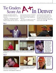
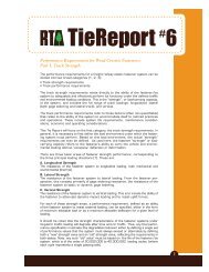
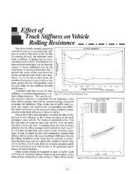
This report presents a review <strong>of</strong> the lateral resistance characteristics <strong>of</strong> wood and concretecross-ties together with a survey <strong>of</strong> techniques, systems and approaches used to increasethe lateral resistance <strong>of</strong> wood tie track to approach that <strong>of</strong> concrete ties. As part <strong>of</strong> thisactivity, the existing wood tie track structure’s lateral resistance was compared to concretetie track, based on extensive testing performed to date in the US and internationally.Different options for increasing the lateral resistance <strong>of</strong> wood tie track are discussedtogether with the expected increased lateral track resistance.<strong>The</strong> data and literature examined included extensive single tie push test data performed bythe Federal Railroad Administration and the AAR, laboratory test data to include the AARtrack lab and overseas, international testing, and studies performed at major internationallaboratories and centers.<strong>Lateral</strong> <strong>Resistance</strong> <strong>of</strong> Cross-<strong>Tie</strong> <strong>Track</strong>As noted in Figure 1, the lateral resistance <strong>of</strong> cross-tie track consists <strong>of</strong> three basic components [1,2, and 3]:• End <strong>Resistance</strong> - resistance between the end <strong>of</strong> the tie and the ballast at theend <strong>of</strong> the tie, primarily the ballast shoulder. ( Fe = Fend)• Bottom <strong>Resistance</strong> - resistance generated by friction/interaction between thebase <strong>of</strong> the cross-tie and the ballast under the tie ( Fb= Fbottom)• Side resistance - resistance generated by friction/interaction between thesides <strong>of</strong> the cross-tie and the ballast between the ties, the crib ballast• ( Fs= Fside)FFigure 1 – <strong>Lateral</strong> <strong>Resistance</strong> Components (Kish)F side F bottom F endF = F s + F b + F e30-35% 35-40% 20-30%,As noted in Figure 1, the bottom resistance or friction represents the largest component <strong>of</strong>lateral resistance, <strong>of</strong> the order <strong>of</strong> 35 to 40%, followed by the side resistance or frictionwhich is <strong>of</strong> the order <strong>of</strong> 30 to 35% and the end resistance which is <strong>of</strong> the order <strong>of</strong> 20 to30%.However, this relationship can change significantly. For example, under a heavy freight caror locomotive, where uplift occurs (Figure 2), the ties can be lifted up from the ballast,reducing the bottom resistance. In this case, the importance <strong>of</strong> the side and end ballastresistance increases significantly.
Dynamic upliftIncreased resistanceReducedresistanceIncreasedresistanceFigure 2: Reduced <strong>Resistance</strong> Due to Uplift <strong>of</strong> the railThus it is important to maintain all three components <strong>of</strong> the ballast resistance. This isparticularly the case for cribs and shoulders which are not <strong>of</strong>ten maintained to the fulldimensions required by the track structure. Thus, adequate shoulders will provide lateralrestraint to the cross-ties (and the track superstructure itself), resisting both short term andlong term lateral movement <strong>of</strong> the track, and facilitating maintenance <strong>of</strong> the trackalignment. This is particularly true for continuously welded rail (CWR) track, whereinadequate ballast shoulders, and the associated inadequate lateral track resistance, canresult in rapid loss <strong>of</strong> alignment or even buckling <strong>of</strong> the track structure. Studies haveshown that inadequate shoulders can result in a loss <strong>of</strong> overall track resistance <strong>of</strong> the order<strong>of</strong> 20 to 30, and in some cases up to 40+ % [1, 2, 3, 4, and 5].Similarly, full cribs will provide longitudinal resistance to the movement <strong>of</strong> the ties, toprevent tie skewing or movement along the track. Tests have shown that half empty cribscan reduce tie longitudinal restraint by the order <strong>of</strong> 30% or more. This longitudinalrestraint is <strong>of</strong> even more importance on grades, where full cribs (together with adequatelongitudinal anchoring) will prevent creep <strong>of</strong> the rail or movement <strong>of</strong> the ties under trafficloading. In addition, the cribs also provide supplemental lateral resistance for the track, <strong>of</strong>the order <strong>of</strong> 30 to 35% 1 <strong>of</strong> the total lateral resistance [1,2,3,4,5].Figure 3 defines the lateral and longitudinal resistance behavior <strong>of</strong> cross-ties in track.1 <strong>The</strong>re is a strong interaction between the crib and base friction lateral resistance.[2]
Figure 3: <strong>Lateral</strong> and Longitudinal track resistanceFocusing on the lateral resistance <strong>of</strong> the track, the lateral track resistance can be defined inone <strong>of</strong> two ways:• <strong>Track</strong> resistance per foot where the total track lateral resistance is obtainedby loaded the track laterally and measuring the lateral deformation curve.<strong>The</strong> lateral resistance is then the applied force divided between the distancethe track is deformed• Single tie push test where a single tie is separated from the track (byremoving the fasteners) and then displaced laterally.Noting that the single tie push test is significantly easier to perform, it has been adopted asthe ‘standard” for lateral resistance measurement in the US.Figure 4 illustrates the shape <strong>of</strong> the load- deflection curve obtained from a single tie pushtest. As can be seen in this Figure for well consolidated track, there is a linear increase inresistance in load until a maximum value Fp is reached. This is termed the Peak <strong>Resistance</strong><strong>of</strong> the tie, after which there is a ‘s<strong>of</strong>tening” in the load deflection behavior. This Fp value isusually defined as the tie lateral resistance as was illustrated in Figure 1. For weaker track,there is no corresponding s<strong>of</strong>tening behavior, so that the Fp value remains constant throughthe balance <strong>of</strong> the load- deflection behavior.
Figure 4: Single tie push test load-deflection curve.Testing in the US and elsewhere has provided the following ranges <strong>of</strong> peak lateralresistance values (per tie); note all values are in lbs. <strong>of</strong> force (Table 1).TABLE 1: <strong>Wood</strong> and Concrete <strong>Tie</strong> lateral resistance (Single <strong>Tie</strong> Push tests)<strong>Wood</strong> <strong>Tie</strong>Concrete tiesStrong > 2500 > 3000Average 2000-2500 2500- 3000Marginal 1500-2000 2000-2500Weak
Table 2: <strong>Lateral</strong> <strong>Resistance</strong> as a function <strong>of</strong> various ballast and track factors ( noteresistance here is defined in lb/in as compared to lb/tie.)N/m17 50014,00010,5007,0003,500
Figures 5 and 6 show the effect <strong>of</strong> tie type and maintenance in graphical format. Again note thattimber ties in recently disturbed (post-maintenance) ballast generate lateral resistance values <strong>of</strong>the order <strong>of</strong> 700 to 800 lbs/tie as compared to concrete ties which generate lateral resistance <strong>of</strong>the order <strong>of</strong> 800 to 1000 lb/tie.. For consolidated track, under comparable conditions, timber tiesgenerate lateral resistance values <strong>of</strong> the order <strong>of</strong> 1300 to 1400 lbs/tie as compared to concrete tieswhich generate lateral resistance <strong>of</strong> the order <strong>of</strong> 2200 to 23000 lb/tie. European data in Figure 6shows comparable lateral resistance values.Figure 5: <strong>Lateral</strong> <strong>Resistance</strong> as a function <strong>of</strong> wood vs. concrete tie and track maintenancetonneslbs.1.14.91.68.45.23in.1.2 2.5 4 5 6 mm
Figure 6: <strong>Lateral</strong> resistance <strong>of</strong> different tie types from European Test Data [3] ( 1 kg = 2.2 lb)Similar differences are observed between wood and concrete ties in their longitudinal resistanceas shown in Table 3.
Table 3:: Longitudinal <strong>Resistance</strong> <strong>of</strong> wood vs. concrete ties ( per tie basis)<strong>Increasing</strong> <strong>Lateral</strong> <strong>Resistance</strong>Table 4 presents different techniques for increasing the lateral resistance <strong>of</strong> cross-ties in ballast tracktogether with their relative influence <strong>of</strong> on the lateral resistance <strong>of</strong> the track [3].
As can be seen from this Table, there are several design features that can provide significantbenefit in increasing lateral track (and tie) resistance.<strong>The</strong>se include:o Increased ballast shoulder width and height (track “benches”).o Compacting/consolidation <strong>of</strong> ballasto Discontinuous tieso <strong>Increasing</strong> <strong>Tie</strong> Height, width and/or length and tie weighto Safety capso Decreasing tie spacingo <strong>Increasing</strong> fastener rotational resistanceo Friction at bottom <strong>of</strong> ties ( grooves)
<strong>The</strong> first two techniques are the most commonly employed techniques both in the US and internationally,and they are effective, however they focus on the ballast as opposed to the ties. Thus they are equallyapplicable to increasing the resistance <strong>of</strong> wood tie track as concrete tie track. Virtually all major USrailways increase shoulder width on CWR track in curves or in buckling prone territory, to increase lateralresistance. <strong>The</strong>y also use ballast consolidators to increase lateral resistance <strong>of</strong> disturbed ballast, such asafter maintenance operations such as tamping, tie insertion, etc. In Europe, the use <strong>of</strong> track benches, toincrease the height <strong>of</strong> the ballast shoulder above top <strong>of</strong> tie has been used and found to be effective [3].<strong>The</strong> use <strong>of</strong> discontinuous ties applies primarily to two-block concrete ties and is not applicable to woodties.<strong>Increasing</strong> the tie height or length can be <strong>of</strong> potential interest, but has a cost impact in direct proportion tothe percentage increase in the amount <strong>of</strong> wood in the tie. While the UP used 9’ ties for many years ( andstill uses them for some applications), the most common length <strong>of</strong> tie is 8 1/2'’. Standard cross-tie heightis 7”, though ties used in less demanding applications are 6” in height. This will be discussed further inthe next section on techniques to improve lateral resistance <strong>of</strong> wood ties.Deceasing tie spacing from the standard 19.5” spacing also represents an economic cost-benefit trade <strong>of</strong>f,however the amount <strong>of</strong> decrease may be limited by the requirements for maintaining sufficient cribspacing to allow for maintenance such as tamping, tie removals, etc.Use <strong>of</strong> end or safety caps will be discussed in detail in the next section on techniques to improve lateralresistance <strong>of</strong> wood ties.<strong>The</strong> effect <strong>of</strong> increased fastener rotation resistance will be discussed in detail in the next section ontechniques to improve lateral resistance <strong>of</strong> wood ties.<strong>The</strong> effect <strong>of</strong> increasing friction on bottom <strong>of</strong> ties will be discussed in detail in the next section ontechniques to improve lateral resistance <strong>of</strong> wood ties.Techniques to Improve <strong>Lateral</strong> <strong>Resistance</strong> <strong>of</strong> <strong>Wood</strong> <strong>Tie</strong>s<strong>Increasing</strong> tie length or height<strong>Increasing</strong> the tie height or length has been shown to increase lateral resistance <strong>of</strong> the tie in ballast, buthas a cost impact in direct proportion to the percentage increase in the amount <strong>of</strong> wood in the tie. Whilethe UP used 9’ ties for many years (and still uses them for some applications), the most common length <strong>of</strong>tie is 8 1/2'’. Standard cross-tie height is 7”, though ties used in less demanding applications are 6” in
height. This is primarily an economic question relating to the increase in cost <strong>of</strong> the ties plus any costsdue to changes in tie handling equipment versus the benefits associated with the increased costs. Thisrequires a detailed cost benefit analysis which is beyond the scope <strong>of</strong> this report. However, cost increasesare primarily linear with change in either length <strong>of</strong> height. <strong>Lateral</strong> resistance increase in linear with lengthfor that percentage <strong>of</strong> lateral resistance due to side pressure (30-35%) but this can be significant forcurves and other areas where lateral track geometry related maintenance costs are high.Deceasing tie spacing from the standard 19.5” spacing also represents an economic cost-benefit trade <strong>of</strong>f,however the amount <strong>of</strong> decrease may be limited by the requirements for maintaining sufficient cribspacing to allow for maintenance such as tamping, tie removals, etc.<strong>Increasing</strong> base or side friction on wood ties<strong>The</strong> effect <strong>of</strong> increasing friction on bottom or sides <strong>of</strong> ties has in fact been an issue addressed with severaltypes <strong>of</strong> concrete tie designs, where there was limited friction between the tie top/side and the ballast.Generally, this has not been the case for traditional hardwood or s<strong>of</strong>twood ties, where the ballast particlepressure at the interface with the tie caused ‘indentations’ in the wood, resulting in a good frictionalcontact.However, studies in Europe with the use <strong>of</strong> ribs or indentations under timber ties result in reportedimprovement in lateral resistance [3]. While this approach has not been used in the US on timber ties, ithas been used effectively on plastic and composite ties to increase lateral resistance though increasingbase friction with the top <strong>of</strong> the ballast under the tie or side friction with the ballast in the cribs (seeFigure 7).
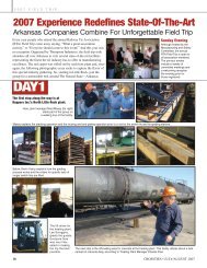
Figure 7: Indentation in Rubber or Composite <strong>Tie</strong>s<strong>Tie</strong> End or Safety CapsUse <strong>of</strong> end or safety caps ( also referred to as sleeper anchors) on timber ties likewise has been usedextensively in Europe to improve lateral resistance <strong>of</strong> wood ties. Figures 8 and 9 show several differentend cap configurations used in Europe.
Figure 8: End or Safety Caps for <strong>Wood</strong> Cross-<strong>Tie</strong>sFigure 9: Vossloh Design Sleeper Anchor for Timber <strong>Tie</strong>s
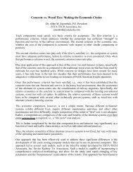
As noted in Figure 10, European practice is to add a safety cap every second or third tie.Figure 10: Use <strong>of</strong> tie safety caps on every tie, every second or third tieAs can be seen in Figures 11 European tests on lateral track resistance <strong>of</strong> ties equipped with safety capsshow a significant increase in lateral resistance <strong>of</strong> the order <strong>of</strong> 50% for non-compacted or disturbedballast. This corresponds to an increase from 600 kg or 1300 lbs. per tie without end caps about 900 kg oralmost 2000 lb with end caps. Note, however that for these tests, there is only a relatively smallimprovement in using safety caps on every tie as opposed to every second tie, as noted in Figure 10.Figure 12 shows that reducing the number <strong>of</strong> safety caps to every third tie results in an approximate 15%reduction in lateral resistance from the every second tie design configuration (for compacted ballast).Thus, as noted previously, it is not necessary to place safety caps on every tie in a curve or in a bucklingprone location, but rather every second or third tie is sufficient (and more economical).
Figure 11: <strong>Lateral</strong> <strong>Resistance</strong> <strong>of</strong> track with and without safety caps (non-compacted ballast) [3]
Figure 12: Effect <strong>of</strong> safety Caps on Compacted ballast [3]Increased Fastener Rotational <strong>Resistance</strong>Several studies have examined the effect <strong>of</strong> fastener rotation resistance, s, which is theproportionality constant between the resistance moment (per unit length <strong>of</strong> rail) and the rotation<strong>of</strong> the rail axis [7,8]. This includes both theoretical analyses and experimental determination.Both the analytical and test results show that when the torsional stiffness <strong>of</strong> the fasteners isvirtually, non-existent, such as the case with cut spike fasteners, the cross-ties act merely asspacers and a bending moment <strong>of</strong> the rail-tie structure is carried by the bending stresses <strong>of</strong> thetwo rails. However, when the fasteners exert a resistance against rotation (s >0) the bendingmoment is carried not only by the bending stresses <strong>of</strong> each rail, but also by the axial forces in therails, as shown in Figure 13. Thus, in general, the both the gage and the fastener resistance willhave an effect on the lateral response when s>0. This is illustrated in Figure 14 which shows theeffect <strong>of</strong> the torsional fastener stiffness, represented by s, on the lateral track displacement νˆ . Ascan be seen from this figure, the lateral displacements for s = 20 ton-m/rad are less than atenth <strong>of</strong> the corresponding values for s = 0. Also, the lateral displacements for s = 50 are lessthan one half <strong>of</strong> those for s = 20.
Thus, based on Figure 14 the effective track lateral bending stiffness (EI) increases withincreasing fastener rotational s. This in turn indicates, that increased lateral resistance <strong>of</strong> wood tietrack can be accomplished by using elastic fasteners with rotational or torsional stiffness greaterthan traditional cut spike track (which approaches s= 0). It should be noted, that this behaviorwill not be seen in a single tie push test, where the tie is disconnected from the fasteners andrails, but is seen when the track superstructure is evaluated as a single entity (corresponding tothe first <strong>of</strong> the two methods <strong>of</strong> determining lateral track resistance discussed at the beginning <strong>of</strong>this report, track resistance per foot where the total track lateral resistance is obtained by loadedthe track laterally and measuring the lateral deformation curve, and the lateral resistance is thenthe applied force divided between the distance the track is deformed.)Figure 13: Effect <strong>of</strong> rotational fastener stiffness, s, on rail stresses.
Figure 14: Effect <strong>of</strong> torsional stiffness <strong>of</strong> fasteners on track lateral displacements
References1. Kish, A., On the Fundamentals <strong>of</strong> <strong>Track</strong> <strong>Lateral</strong> <strong>Resistance</strong>, American <strong>Railway</strong>Engineering and Maintenance <strong>of</strong> Way Association, 20112. Samavedan, G. et al, “<strong>Track</strong> <strong>Resistance</strong> Characterization and Correlation Study”, FRAReport DOT/FRA/ORD-94/07, January 19953. Dogneton, P., “Axial and <strong>Lateral</strong> <strong>Track</strong> Ballast <strong>Resistance</strong>”, Railroad <strong>Track</strong> Mechanicsand Technology, Pergammon Press, New York, 19784. Lichtberger, R., <strong>Track</strong> Compendium, Eurail Press, Hamburg, 20115. Selig, E. T. and Waters, J. M., <strong>Track</strong> Geotechnology and Substructure Management,Thomas Telford Press, London, 19946. American <strong>Railway</strong> Engineering and Maintenance <strong>of</strong> Way Association, “Manual for<strong>Railway</strong> Engineering” 2012.7. Kerr, A. D., and Zarembski, A. M., “<strong>The</strong> Response Equations for a Cross-tie <strong>Track</strong>”,ACTA Mechanical, 40, 253-276, 1981.8. Kerr, A. D., and Zarembski, A. M., “On the New Equations for the Cross-<strong>Tie</strong> <strong>Track</strong>Response in the <strong>Lateral</strong> Plane”, Rail International, Number 6, 1986.