TieReport #6 - Railway Tie Association
TieReport #6 - Railway Tie Association
TieReport #6 - Railway Tie Association

Create successful ePaper yourself
Turn your PDF publications into a flip-book with our unique Google optimized e-Paper software.
<strong><strong>Tie</strong>Report</strong>TECHNICAL # 6Performance Requirements for Wood Crosstie Fasteners:Part I, Track StrengthThe performance requirements for a freight railway elastic fastener system can bedivided into two broad categories [1, 2, 3]:• Track strength requirements• Track performance requirementsThe track strength requirements relate directly to the ability of the fastener/tiesystem to adequately and effectively perform its functions under the defined trafficand environmental loading conditions. This is the “strength”, or load-carrying capacity,of the system, and includes the full range of track loadings: longitudinal; lateral(both gage widening and lateral track); and vertical.The track performance requirements refer to those factors (often non-quantifiable)that relate to the ability of the system to accommodate itself to railroad practicesand operations. These include system life requirements, maintenance considerations,economic and operating considerations.This <strong>Tie</strong> Report will focus on the first category, the track strength requirements. Ingeneral, it is necessary to first define the load environment under which the fasteningsystem must perform. Based on this load environment, the actual “strength”requirements can then be defined. As used here, the fastener “strength” or loadcarryingcapacity refers to the fastener’s ability to carry the vehicle and environmentalloading without “excessive” deflection or deformation.There are three basic areas of fastener strength performance, corresponding tothe three principal loading directions [1]. These are:A. Longitudinal StrengthThe resistance of the fastener system to longitudinal loading, both mechanical andenvironmental (thermal).B. Lateral StrengthThe resistance of the fastener system to lateral loading. From the fastener perspective,this consists primarily of gage widening resistance, the resistance of thefastener system to static or dynamic gage widening.C. Vertical StrengthThe resistance of the fastener system to vertical loading. This is to include the ability ofthe fastener to attenuate dynamic impact loading and to resist uplift forces.For each of these strength areas, a performance requirement, defined as an abilityof the fastener system to resist external loading, can be specified, either in the formof maximum allowable load or as a maximum allowable deflection for a given level ofloading.It should be noted that the strength characteristics of the fastener systems underlong-term traffic loading will degrade after time and/or traffic. Thus, any final performancespecification must take this degradation behavior either by defining a single setof performance values that the system must always exceed or alternately by definingboth a “new” strength value and an “old” strength value, reflecting the requirements inboth states. Note: any such “old” value” must be based on the life of the fastener/tiesystem, which is of the order of 20,000,000 to 40,000,000 loading cycles, (whereeach cycle represents a single passing axle).1
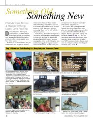
<strong>Tie</strong> Report # 6: Performance Requirements for Wood Crosstie Fasteners(continued)A. Longitudinal StrengthLongitudinal fastener strength is the ability of the fastener system to provide longitudinalrestraint to the rail and prevent rail movement or creepage under all loading conditions. Asnoted previously, longitudinal loading can be due to train action, such as train or engine brakingand/or acceleration, and to environmental action, specifically the variation in temperature,both rail and ambient.The function of the fastener is to provide longitudinal restraint to prevent any movement of therail with respect to the ties. Under mechanical loading, this is simply the case of each fastenerpicking up a portion of the load, up to its maximum capacity, until the entire longitudinal loadis restrained. In the case of thermal loading, the distribution of longitudinal consists of twodistinct loading zones, the two end zones or “breathing” zones in which longitudinal movementof the rail takes place and the center “constrained” zone in which no longitudinal movementoccurs. Therefore, the fastener longitudinal restraint is most critical in these end or “breathing”zones. These zones are at the ends of the Continuously Welded Rail (CWR) strings orat each side of a rail gap, such as occurs during a rail pull-apart or break. Good longitudinalrestraint strength is required to prevent development of an excessive rail end opening or “gap”at any discontinuity in the CWR or in the event of a pull-apart or rail break where the break orgap must be controlled to avoid an excessive gap in the rail.AREMA specifies 2400 lbs. (2.4 Kips) fastener restraint for passing of the fastener longitudinalrestraint test and 2500+ lbs. (2.5+ Kips) in its rail fastening system performance table,which is included in Table 1 below [4]. For wood ties at 19.5-inch spacing, this correspondsto a longitudinal restraint of the order of 1500 lb./ft. Most elastic fastener systems meet orexceed these limits.In the case of wood tie/cut spike/rail anchor system, rail anchors have longitudinal restraintvalues (new) of the order of 5000+ lbs. (AREMA requires a minimum of 5000 lbs.). This, whenplaced in a conventional box anchor, every other tie configuration, corresponds to a longitudinalstrength of 1500 lbs./ft., corresponding to the elastic fastener values.B. Lateral Gage StrengthAs noted earlier, lateral gage strength refers to the ability of the fastener system to limit theamount of gage widening, both static and dynamic. This is an important parameter, since akey fastener function is to maintain track gage under loading, i.e., to prevent dynamic gagewidening. Gage widening is defined to be any increase in the standard gage of the track structure.Gage widening is associated with threedistinct mechanisms as follows:A. Rail wear; abrasive wear on the railhead,particularly the gage face of the high rail.Rail wear is outside the scope of thefastener system,although it is slightlyaffected by fastener stiffness.Figure 1: Rail Rotation UnderLateral and Vertical LoadingB. Rail translation; rigid body movementof the rail, without any rotation, i.e., lateralmovement of the base of the rail.C. Rail rotation; rotation of the rail about itslongitudinal axis, i.e., overturning (Figure 1).From the point of view of track strength,modes B and C are of concern.2
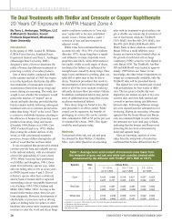
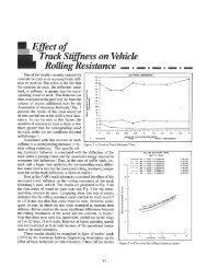
<strong>Tie</strong> Report # 6: Performance Requirements for Wood Crosstie Fasteners(continued)Fastener strength is generally defined in terms of deflection under loading, under defined lateral andvertical wheel/rail loading, in which case the combined deflection (B + C) is considered [3].Table 1 presents several parameters that relate directly to the lateral gage strength of thefastener/tie system. Note that these are a function of the wood type as well as the fastener,since they represent the strength characteristics of the combined wood tie/fastener system.These include:• Lateral rail restraint, defined by AREMA [4] to be a measure of the load necessary to move(B) or rotate (C) the rail section perpendicular to the running axis of the rail.• Fatigue L/V test, defined by AREMA [4] to be a repeated load test conducted onthe fastening system to determine its resistance to rail movement under repeated load. This testlooks at the long-term performance and degradation of the tie/fastener system.Tests comparing the gage widening strength (deflection under load) have shown that the lateralgage strength of new hardwood ties with elastic fasteners are comparable to (and in somecases greater than) the strength of concrete ties with the same elastic fasteners [5].Table 1: Properties of Rail Fastener Systems for Wood <strong>Tie</strong>sOakNorthernMixedHardwoodsSouthernMixedHardwoodsSouthernYellow PineSoftwoodDouglasFirLongitudinal Rail Restraint (kips) 2.5+ 2.5+ 2.5+ 2.5+ 2.5+ 2.5+Lateral Rail Restraint (kips) 18-30 18-30 18.3+ 18.3+ 18.3+ 18.3+Fatigue L/V Tests 0.5-4.0 0.5-4.1 0.5-4.2 1.2 1.2 1.2Spike/Screw Pullout Test (lbs) 5,000-6,600+Impacts on Fastening System (lbs/in 2 ) 1,000-4,0005,000-6,600+1,000-4,0005,000-6,600+1,000-4,0003,000-5,0001,000-4,0003,000-5,0001,000-4,0003,000-5,0001,000-4,000C. Vertical StrengthVertical strength refers to the ability of the tie/fastener system to respond to loading in thevertical plane. [It includes the ability of the fastening system to withstand and attenuate highlevels of dynamic loading and for wood tie track, to resist pull-out of the fasteners during upliftof the track (as a railroad wheel passes by).Traditional analyses of vertical dynamic effects (i.e., speed effects) calculate speed factors ofthe order of 1.6 times the static wheel loads at speeds of 60 mph (based on the AREMA speedeffect formula [4]). Defects on the rail surface (corrugations, engine burns, battered welds),rail joints, or imperfections in the wheel tread, i.e., flats or out-of-round wheels, can magnifythe vertical loads by factors of 2 to 4 [6], though recent measurements using wheel impactdetectors have found factors of 5 and higher (Figure 2 [6]).Table 1 presents several parameters that relate directly to the vertical strength of the fastener/tiesystem. Note, as in the case of the lateral strength, these parameters are a function ofthe wood type as well as the fastener, since they represent the strength characteristics of thecombined wood tie/fastener system. These include:• Spike/Screw Pullout Test defined by AREMA [4] to be the force required to remove thefastener (screw or spike) from the tie. A measure of the vertical strength of the fasteningsystem.• Impact on Fastening System. Defined by AREMA [4] to be the ability of the rail seat pad (orwood tie) to attenuate the effect of wheel and rail impact loads on ties.3
<strong>Tie</strong> Report # 6: Performance Requirements for Wood Crosstie Fasteners(continued)Figure 2: Dynamic Impact Factor Associated Wheel Flats [6]Dynamic Impact Factor(Ratio of Flat Wheel Stress to Round Wheel Stress In Base of Rail)3.503.002.502.001.501.004.003.503.002.502.001.501.004.504.003.503.00• 100-lb. RA-A Rail — Full Load• 131-lb. RE Rail — Full Load21/2 in. Flat Spot(Equivalent to .050 corrugation)• 100-lb. RA-A Rail — Full Load• 131-lb. RE Rail — Full Load31/2 in. Flat Spot(Equivalent to .90 corrugation)131-lb. RE Rail — Full Load41/2 in. Flat Spots on Both Wheels+ 41/2 in. Flat Spots on Rounded 2 in. at Ends*Note: Many of the keyproperties of the fastenerswill vary with wood type.In order to allow for thepotential use of a broad rangeof wood types, the wood tieproperties have been dividedinto six (6) categories of woodas presented in Table 1[4].The fastener propertiespresented in Table 1 areconsistent with thosepresented in the Manualfor <strong>Railway</strong> Engineeringof the American <strong>Railway</strong>Engineering andMaintenance of way<strong>Association</strong> (AREMA) [4].2.502.001.501.0041/2 in. Flat Spot(Equivalent to .150 corrugation)Speed in Miles Per HourREFERENCES1. Zarembski, A. M., “Performance Characteristics for Wood <strong>Tie</strong> Fasteners,” Bulletin of the American <strong>Railway</strong> Engineering <strong>Association</strong>,Bulletin 697, Volume 85, October 1984, pp. 341-369.2. <strong>Railway</strong> <strong>Tie</strong> <strong>Association</strong>, “Wood <strong>Tie</strong>-Fastener Performance Specifications for Transit and Rail Passenger Operations,” November1991.3. Zarembski, A. M., “Wood <strong>Tie</strong> Fastener Performance Requirements: The User’s Points of View,” Symposium on Elastic TrackFasteners, American <strong>Railway</strong> Engineering <strong>Association</strong>, Omaha, NE, June 1992.4. American <strong>Railway</strong> Engineering and Maintenance of way <strong>Association</strong> (AREMA), Manual for <strong>Railway</strong> Engineering, 2007, Chapter 30,Section 30-A-11.5. Choros, J., “Laboratory Tests of Three Alternate Track Structures,” AAR Report R-614, September 1985.6. AAR Joint Committee on Relation Between Track and Equipment, “Effect of Flat Wheels on Track and Equipment,” AAR ReportMR113, May 1951.4The <strong>Railway</strong> <strong>Tie</strong> <strong>Association</strong> • 115 Commerce Drive, Suite C • Fayetteville, GA 30214 • P: 770-460-5553 • F: 770-460-5573 • ties@rta.org