AN 999: GaAs MMIC Assembly and Handling Guidelines
AN 999: GaAs MMIC Assembly and Handling Guidelines
AN 999: GaAs MMIC Assembly and Handling Guidelines

You also want an ePaper? Increase the reach of your titles
YUMPU automatically turns print PDFs into web optimized ePapers that Google loves.
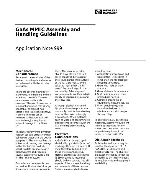
H<strong>GaAs</strong> <strong>MMIC</strong> <strong>Assembly</strong> <strong>and</strong>H<strong>and</strong>ling <strong>Guidelines</strong>Application Note <strong>999</strong>MechanicalConsiderationsBecause of the small size of thedevices, h<strong>and</strong>ling should alwaysbe performed with the aid of amicroscope.There are several methods forpicking up, transferring <strong>and</strong> dieattaching these ICs. The mostcommon method is withtweezers. The use of tweezers isa manual operation that is veryadaptable, or product nonspecific,<strong>and</strong> is also inexpensive.A difficulty in the use oftweezers is that operator skill(<strong>and</strong> training) is required toprevent damage to the <strong>GaAs</strong>ICs.The use of an "inverted-pyramid"vacuum collet is attractive whenusing semi-automatic die attachequipment. This method has thepotential of causing less damageto the die, but the productspecificcollets are more costlythan tweezers <strong>and</strong> require aseveral week turnaround timefor their manufacture.Grounded vacuum pencils canbe used for the transfer of largerdie at room temperature condi-tions. The vacuum pencilsshould have plastic tips (butcare should still be taken) orthey could damage the surfaceof the IC. Care must also betaken to insure that the ICdoesn't become lodged in thevacuum tip. Advantages ofvacuum pencils are their adaptabilityto various die sizes <strong>and</strong>their low cost.Although alcohol-moistenedQ-tips <strong>and</strong> wooden probes arecommonly used for transferringdevices, their use is stronglydiscouraged. When materialsuch as wood <strong>and</strong> contaminatedalcohol come in contact with theICs, bonding problems mayresult.ElectricalConsiderationsA <strong>GaAs</strong> IC can be destroyedelectrically by a static (or other)discharge through the device. Itmust therefore be h<strong>and</strong>led sothese effects cannot occur.Normal electrostatic discharge(ESD) preventive measuresshould be incorporated into allaspects of the storage, h<strong>and</strong>ling<strong>and</strong> assembly of these devices.Specific measures to be takenshould include:1. Anti-static storage trays <strong>and</strong>boxes if the ICs are kept inother than the HP suppliedshipping containers.2. Grounded mats at workstations.3. Ground straps for operators.4. Static eliminators on compressedgas nozzles.5. Common grounding ofequipment, mats, straps, etc.6. Wire bonding sequenceshould be designed toeliminate static dischargesthrough chip.In addition to ESD preventionmeasures, assembly equipmentshould be inspected for anypower line transients that maycouple into equipment thatcomes in contact with ICs.Die Attach MethodsBoth solder <strong>and</strong> epoxy may beused for the die attach of HP<strong>GaAs</strong> ICs to substrates <strong>and</strong>metal structures. The choice ofdie attach method is influencedprimarily by thermal conductivityrequirements <strong>and</strong> equipmentavailability.
3Thermosonic capillary bond schedule:Equipment:MechEl thermosonic capillary bonderBonding tool: Capillary, per Figure 2Wire:Gold wire, 0.0007" diameter,0.5-2.0% elongation.Breaking strength 5-8 gramsGram force:30 ± 1 gramStage temperature: 150 ± 2°CUltrasonic parameters: power: 60 ± 1 dB(for bond pull on IC) dwell: 66 ± 8 msecSummaryThis guideline is the result ofexperience gained at HPdivisions that assemble <strong>GaAs</strong>ICs into hybrid circuits. It isdynamic rather than static <strong>and</strong>,by its nature will change as wegain more experience with theh<strong>and</strong>ling <strong>and</strong> assembly of <strong>GaAs</strong>ICs. Your insights, as the customer,are encouraged <strong>and</strong> willbenefit other <strong>GaAs</strong> IC users.ThermocompressionBondingThis method generally involveshigher temperatures than thoserequired with thermosonicbonding. Thermocompressionbonds are usually formed withbonding tool temperatures of350°C <strong>and</strong> stage temperaturesof 250°C, although processeshave been developed that uselower temperatures. When thehybrid circuit cannot tolerate astage temperature of 250°C, thebonding tool temperature <strong>and</strong>/orforce is increased.Finally, this guideline does notpreclude the use of any assemblymethods not specificallymentioned.Thermocompression wedge bond schedule:Equipment:Westbond thermocompression bonderBonding tool:Small Precision Tools wedge(SPT-1002-A-W-2015-L-F)Wire:Gold wire, 0.0007" diameter,3.6% elongation.Gram force:28-30 gramsStage temperature: 250°CTool temperature: 220°C"Reprinted with permission from the 1988 IEEE MTT-S International Symposium, New York, N.Y., May 25-27, 1988, pages 499-502"© 1988 IEEE MTT-S Digest.
HFigure 1. Wedge Bonding Tool.Figure 2(a). Thermosonic Capillary Bonding Tool.Figure 2(b). Detail of Capillary.For technical assistance or the location of your nearest Hewlett-Packard sales office, distributor or representative call: Americas/Canada: 1-800-235-0312 or 408-654-8675 Far East/Australasia: (65) 290-6305 Japan: (81 3) 3331-6111 Europe: Call your localHP sales office listed in your telephone directory. Ask for a Components representative.Data subject to change. Copyright © 1995 Hewlett-Packard Co. Obsoletes 5091-1988E (6/91)Printed in U.S.A. 5964-6644E (12/95)