Collapsible Core & Collapsible Minicore - Roehr Tool Corporation
Collapsible Core & Collapsible Minicore - Roehr Tool Corporation
Collapsible Core & Collapsible Minicore - Roehr Tool Corporation
You also want an ePaper? Increase the reach of your titles
YUMPU automatically turns print PDFs into web optimized ePapers that Google loves.
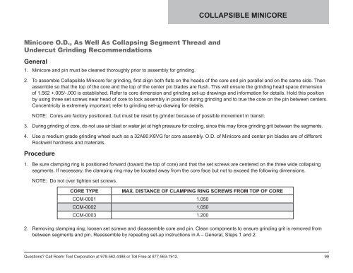
COLLAPSIBLE MINICORE<strong>Minicore</strong> O.D., As Well As Collapsing Segment Thread andUndercut Grinding RecommendationsGeneral1. <strong>Minicore</strong> and pin must be cleaned thoroughly prior to assembly for grinding.2. To assemble <strong>Collapsible</strong> <strong>Minicore</strong> for grinding, first align both flats on the heads of the core and pin parallel and on the same side. Thenassemble so that the top of the core and the top of the center pin blades are flush. This will ensure the grinding head space dimensionof 1.562 +.005/-.000 is established. Refer to core dimension and grinding set-up drawings and information for details. Hold this positionby using three set screws near head of core to lock assembly in position during grinding and to true the core on the pin between centers.Concentricity is extremely important; refer to grinding set-up drawing for details.NOTE: <strong>Core</strong>s are factory positioned, but must be reset by grinder because of possible movement in transit.3. During grinding of core, do not use air blast or water jet at high pressure for cooling, since this may force grinding grit between the segments.4. Use a medium grade grinding wheel such as a 32A80.K8VG for core assembly. O.D. of <strong>Minicore</strong> and center pin blades are of differentRockwell hardness and materials.Procedure1. Be sure clamping ring is positioned forward (toward the top of core) and that the set screws are centered on the three wide collapsingsegments. If necessary, the clamping ring may be located away from the core face but not to exceed the following dimensions.NOTE: Do not over tighten set screws.CORE TYPE MAX. DISTANCE OF CLAMPING RING SCREWS FROM TOP OF CORECCM-0001 1.050CCM-0002 1.050CCM-0003 1.2002. Removing clamping ring, loosen set screws and disassemble core and pin. Clean components to ensure grinding grit is removed frombetween segments and pin. Reassemble by repeating set-up instructions in A – General, Steps 1 and 2.Questions? Call <strong>Roehr</strong> <strong>Tool</strong> <strong>Corporation</strong> at 978-562-4488 or Toll Free at 877-563-1912.99


