Collapsible Core & Collapsible Minicore - Roehr Tool Corporation
Collapsible Core & Collapsible Minicore - Roehr Tool Corporation
Collapsible Core & Collapsible Minicore - Roehr Tool Corporation
You also want an ePaper? Increase the reach of your titles
YUMPU automatically turns print PDFs into web optimized ePapers that Google loves.
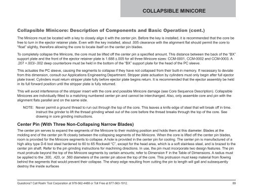
COLLAPSIBLE MINICORE<strong>Collapsible</strong> <strong>Minicore</strong>: Description of Components and Basic Operation (cont.)The <strong>Minicore</strong> must be located with a key to closely align it with the center pin. Before the key is installed, it is recommended that the core befree to turn in the ejector retainer plate. Even with the key installed, about .005 clearance with the alignment flat should permit the core to“float” slightly, therefore allowing the core to locate itself on the center pin blades.To completely collapse the <strong>Minicore</strong>, the core must be lifted off the center pin a specified amount. This distance between the back of the “BX”support plate and the front of the ejector retainer plate is 1.688 ±.005 for all three <strong>Minicore</strong> sizes: CCM-0001, CCM-0002 and CCM-0003. A.207 +.003/-.002 deep counterbore must be held in the bottom of the “BX” support plate for the head of the PC sleeve.This actuates the PC sleeve, causing the segments to collapse if they have not collapsed from their built-in memory. If necessary to deviatefrom this dimension, consult our Applications Engineering Department. Stripper plate actuation by cylinders must only begin after full ejectorplate travel. Cylinders must return stripper plate fully before ejector plate begins return. It is recommended that the ejector assembly be heldin its full forward position until the stripper plate is fully returned.This will avoid interference of the stripper insert with the core and possible <strong>Minicore</strong> damage (see <strong>Core</strong> Sequence Description). <strong>Collapsible</strong><strong>Minicore</strong>s are individually fitted to a matching numbered center pin and cannot be interchanged. Also, only assemble core and pin with thealignment flats parallel and on the same side.NOTE: Never permit a ground thread to run out through the top of the core. This leaves a knife edge of steel that will break off in time.Instruct the grinder to lift the thread grinding wheel out of the core before the thread breaks through the top of the core. Seedrawing in core grinding instructions.Center Pin (With Three Non-Collapsing Narrow Blades)The center pin serves to expand the segments of the <strong>Minicore</strong> to their molding position and holds them at this diameter. Blades at themolding end of the center pin fit closely between the collapsing segments of the <strong>Minicore</strong>. When the core is lifted off the center pin blades,room is provided for the <strong>Minicore</strong> segments to collapse. A hole is provided in the center pin for cooling. The center pin is manufactured of ahigh alloy type D-6 tool steel hardened to 60 to 65 Rockwell “C”, except for the head area, which is a soft stainless steel, and is brazed to thecenter pin shaft. Refer to the pin grinding instructions for machining directions. In use, the pin must incorporate two design features. The pinmust protrude beyond the top of the <strong>Minicore</strong> segments by certain amounts; refer to Dimension F in the Table of Dimensions. A radius mustbe applied to the .300, .420, or .560 diameters of the center pin above the top of the core. This protrusion must keep material from flowingbehind the segments that would prevent their collapse. The sharp edge resulting from cutting the pin to length will gall and subsequentlydestroy the inside surfacesQuestions? Call <strong>Roehr</strong> <strong>Tool</strong> <strong>Corporation</strong> at 978-562-4488 or Toll Free at 877-563-1912.89


