Expert R/AFN Retrograde /Antegrade Femoral Nail. - Osteosyntese
Expert R/AFN Retrograde /Antegrade Femoral Nail. - Osteosyntese
Expert R/AFN Retrograde /Antegrade Femoral Nail. - Osteosyntese
- No tags were found...

Create successful ePaper yourself
Turn your PDF publications into a flip-book with our unique Google optimized e-Paper software.
Table of ContentsIntroductionFeatures 2AO/ASIF principles of internal fixation 7Indications 9Cases 10<strong>Retrograde</strong> approachOpening the distal femur 12Reaming (optional) 21Inserting nail 22Standard locking 27End cap insertion 32Spiral blade locking 33End cap insertion 39Freehand locking 40Interlocking with PAD for <strong>Expert</strong> RFN 47<strong>Antegrade</strong> approachOpening the proximal femur 52Reaming (optional) 61Inserting nail 62Standard locking 66End cap insertion 67Freehand locking 69Synthes 1
Implant removal70Implants<strong>Nail</strong>s 75Locking implants 79InstrumentsStandard instrumentation 83Optional instruments 89Vario Case 91Power tools 93DFN compatibility and instrumentation upgrade94Image intensifier controlWarningThis description is not sufficient for immediate application ofthe instrumentation. Instruction by a surgeon experienced inhandling this instrumentation is highly recommended.2 Synthes <strong>Expert</strong> <strong>Retrograde</strong> /<strong>Antegrade</strong> <strong>Femoral</strong> <strong>Nail</strong> Technique Guide
Synthes 3
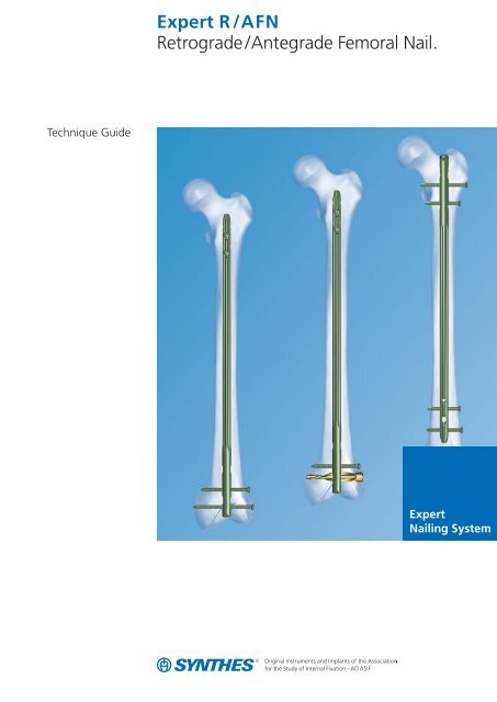
<strong>Expert</strong> <strong>Retrograde</strong>/<strong>Antegrade</strong><strong>Femoral</strong> <strong>Nail</strong>. New Versatile Systemfor Treatment of Diaphyseal andMetaphyseal Fractures.Advanced nail designThe new nail design offers great flexibility– One system for retrograde and antegrade technique– One system for left and right femur– Anatomic bend for ease in insertion and extraction– Cannulation of all nails for guided insertion in reamedand unreamed technique– Large portfolio with nail diameters rangingfrom 9.0 to 15.0 mm and lengths rangingfrom 160 to 480 mm– Versatile locking configuration for static, dynamic,standard and spiral blade lockingretrogradeRFN, 160–200 mmstraightretrogradeRFN, 220–280 mmantecurvature 1500 mmretrogradeR /<strong>AFN</strong>, 300– 480 mmantecurvature 1500 mmantegradeR /<strong>AFN</strong>, 300– 480 mmantecurvature 1500 mm4 Synthes <strong>Expert</strong> <strong>Retrograde</strong> /<strong>Antegrade</strong> <strong>Femoral</strong> <strong>Nail</strong> Technique Guide
Unique distal locking optionsThe unique distal combination hole enables the optimallocking for every anatomical situation and fracture type. Thesurgeon can intraoperatively choose between spiral bladelocking (with one spiral blade and one locking screw)and standard locking (with two locking screws). The end capwith self-retaining Stardrive recess allows for angularstable locking of the most distal locking implant in bothconfigurations.Synthes 5
Improved stabilityEnd Caps:– Self-retaining Stardrive recess foreffortless and secure end cap pick-up and insertion– Possibility to block spiral blade or most distal (retrograde)or most proximal locking screw (antegrade)for absolute angular stability– End cap prevents ingrowth of tissue and facilitatesnail removal.screws with h exalobularStardriveT40This patient has some Sy nthes locking10664ISOint ernal driveto ENac cordingLocking Screws:– Double thread for more contact points leadingto enhanced stability– Larger cross-section for improved mechanical resistance– Thread closer to screw head providing better bonepurchase and improved stability– Self-holding Stardrive recess for effortless andsecure locking screw pick-up– Titanium alloy TAN for improved mechanical andfatigue properties– Adapted locking screw diameter to nail diameter:– 5.0 mm for nails 9.0 –13.0 mm– 6.0 mm for nails 14.0 and 15.0 mmscrews with h exalobularStardriveT25This patient has some Sy nthes locking10664ISOint ernal driveto ENac cordingSpiral Blades:– Optimal hold in osteoporotic bone by increasedsurface area– Angular stable locking by end cap– Titanium alloy TAN for improved mechanical andfatigue properties6 Synthes <strong>Expert</strong> <strong>Retrograde</strong> /<strong>Antegrade</strong> <strong>Femoral</strong> <strong>Nail</strong> Technique Guide
AO/ASIF principles ofinternal fixationIn 1958, the AO/ASIF (Association for the Study of InternalFixation) formulated four basic principles 1 , which havebecome the guidelines for internal fixation in general, andintramedullary nailing in particular:Anatomic reductionBefore inserting the nail, the reduction can be achievedmanually, using a reduction table, an external fixatoror a distractor. A guide wire marks the prescribed pathinto the medullary canal and secures alignment ofthe fragments while the cannulated nail is being insertedover the wire (solid nail design will not allow thisprocedure). The nail insertion is generally monitoredusing x-rays. The nail is then locked proximally and distallyto the bone fragments in order to hold the reduction.Stable fixationThe intramedullary nail acts as an internal splint that controlsbut does not prevent micromovements of the fragments.It provides a relative stability that leads to an indirect healingthrough callus formation. The intramedullary nail allowsfor restoration of length, and axial and torsional orientationof the injured bone. The nails and the locking screwsare available in different diameters and lengths that allowthe surgeon to optimise stability. The judicious choiceof locking options (number, position and direction)in the proximal and distal parts of the nail further improvesthe stability of the implant construct to the bone.1M. E. Müller, M. Allgöwer, R. Schneider and R. Willenegger (1991)AO Manual of Internal Fixation, 3rd Edition. Berlin: Springer.Synthes 7
Preservation of blood supplyWhen the canal is not reamed, intramedullary nailinggenerates minimal trauma to the endosteum and, therefore,the blood supply is maximised through the uninjuredendosteum and periosteum. Reaming the canal temporarilydisrupts the endosteal blood supply but probably stimulatesthe revascularisation and therefore the bone healing.Early, active mobilisationIntramedullary nailing, combined with the AO technique,provides relatively stable fracture fixation with minimal traumato vascular supply. This helps to create an improved environmentfor bone healing, accelerating the patient’s returnto previous mobility and function.8 Synthes <strong>Expert</strong> <strong>Retrograde</strong> /<strong>Antegrade</strong> <strong>Femoral</strong> <strong>Nail</strong> Technique Guide
IndicationsIndications for retrograde approachIn retrograde approach, the <strong>Expert</strong> <strong>Retrograde</strong> /<strong>Antegrade</strong><strong>Femoral</strong> <strong>Nail</strong> is indicated for fractures in the distal femur:– 33-A1/A2/A3– 33-C1/C2/C3.1For the 33-C fractures, the <strong>Expert</strong> <strong>Retrograde</strong> /<strong>Antegrade</strong><strong>Femoral</strong> <strong>Nail</strong> should be used in combination with other implants(not shown in the illustration).Additionally, the <strong>Expert</strong> <strong>Retrograde</strong> /<strong>Antegrade</strong> <strong>Femoral</strong> <strong>Nail</strong>is indicated for fractures in the femoral shaft:– 32-A/B/C (except 32-A[1-3].1 and 32-B[1-3].1(subtrochanteric fractures))in case of:– combination with fractured patella– ipsilateral femur/tibia fractures (floating knee)– combination with fractured acetabulum, pelvis,or femoral neck– combinations of the fractures mentioned above– pronounced adipositas– pregnancy– polytrauma (if numerous surgical teams are involvedin treatment of patient)Note: In case of osteoporotic bone, it is strongly recommendedto utilise spiral blade locking in the distal femur.Indications for antegrade approachIn antegrade approach, the <strong>Expert</strong> <strong>Retrograde</strong> /<strong>Antegrade</strong><strong>Femoral</strong> <strong>Nail</strong> is indicated for fractures in the femoral shaft:– 32-A/B/C (except 32-A[1-3].1 and 32-B[1-3].1(subtrochanteric fractures))Synthes 9
CasesCase 1<strong>Retrograde</strong> approach – standard lockingCase 2<strong>Retrograde</strong> approach – spiral blade lockingCase 3<strong>Antegrade</strong> approach – standard locking10 Synthes <strong>Expert</strong> <strong>Retrograde</strong> /<strong>Antegrade</strong> <strong>Femoral</strong> <strong>Nail</strong> Technique Guide
preoperativepostoperativepreoperativepostoperativepreoperativepostoperativeSynthes 11
<strong>Retrograde</strong> approach –Opening the distal femur1Position patientPosition the patient supine on a radiolucent table.The knee of the injured leg should be flexed 70 to 90º allowingfor correct reduction of the fracture and localisation ofthe nail entry point. A leg roll may be used to allow properreduction and stabilisation of the fracture.Position the image intensifier in such a way that visualisationof the femur including the proximal and distal endsis possible in AP and lateral view.The contralateral leg should be flexed in the hip and inthe knee and rested in an elevated position to enable visualisationby image intensifier.2Reduce fracturePerform closed reduction manually by axial traction underimage intensifier. In case of older fractures, the use ofthe large distractor (394.350) or pinless fixator (186.310) maybe appropriate under certain circumstances.Note: Intra-articular fractures should be stabilised withinterfragmentary screw fixation prior to insertion of the nail.The screws should be positioned to not interfere with thepath of the nail.12 Synthes <strong>Expert</strong> <strong>Retrograde</strong> /<strong>Antegrade</strong> <strong>Femoral</strong> <strong>Nail</strong> Technique Guide
3Measure for length and diameter of nailInstruments03.010.020 Radiographic Ruler for <strong>Expert</strong><strong>Femoral</strong> <strong>Nail</strong>s, length 475 mm03.010.023 Radiographic Ruler for <strong>Nail</strong> Diametersfor <strong>Expert</strong> <strong>Femoral</strong> <strong>Nail</strong>s,length 365 mmThe required nail length must be determined after reductionof the upper leg fracture.Position the image intensifier as for an AP view of the distalfemur. Using long forceps, hold the ruler parallel to thefemur on the lateral side of the upper leg. Position the rulersuch that the distal end is at the desired nail insertion depth.Mark the skin at that site.Synthes 13
Move the image intensifier toward the proximal end of thefemur, align the distal end of the ruler with the skin markingand record an AP x-ray of the proximal femur. Check thereduction and read off the required nail length on the ruleras it appears in the x-ray.Notes: It is recommended that the tip of the nail is at least5 cm above the most proximal extension of the fracturezone. Attention must be paid in the area 4 to 6 cm belowthe Lesser Trochanter because of the A. femoralis andthe branches of the N. femoralis. In cases where such longnails (> 320 mm) are used, it is recommended to placethe AP locking as proximal as possible and above the LesserTrochanter.The possibility of dynamisation must also be consideredwhen determining the nail length and a correspondinglyshorter nail should be chosen. The locking screw inthe dynamic locking option can move by up to 5 mm distally.AlternativesDetermine the nail length by the above procedure onthe uninjured leg or before draping (non-sterile) or comparethe length of two identical SynReam reaming rods 2.5 mm (352.032).14 Synthes <strong>Expert</strong> <strong>Retrograde</strong> /<strong>Antegrade</strong> <strong>Femoral</strong> <strong>Nail</strong> Technique Guide
Place the radiographic ruler for nail diameters over the femurso that the measuring edge is located over the isthmus.Select the nail diameter shown when the medullary canal /cortex transition is still visible on both sides of the marking(12 mm in this example).If the reamed technique is used, the diameter of the largestmedullary reamer applied must be 0.5 to 1.5 mm larger thanthe nail diameter.4ApproachFor 33-A.X and 32-X.X fractures either make a transligamental(ligamentum patellae) or a parapatellar incision.For 33-C.X fractures either make a medial or a lateralparapatellar approach depending on the type and locationof fracture.Synthes 15
5Determine entry pointThe entry point for the <strong>Expert</strong> <strong>Retrograde</strong> /<strong>Antegrade</strong><strong>Femoral</strong> <strong>Nail</strong> is in line with the medullary canal. The point isat the top of the intercondylar notch, just anterior andlateral to the femoral attachment of the posterior cruciateligament.The entry point is determinant for the entire operation,especially for the optimal final position of the nail in themedullary canal respecting the anatomical conditions.This is mostly important for distal metaphyseal fracturesregarding correct fragment placement.mediallateral16 Synthes <strong>Expert</strong> <strong>Retrograde</strong> /<strong>Antegrade</strong> <strong>Femoral</strong> <strong>Nail</strong> Technique Guide
6Insert guide wire7– 9ºInstruments357.127 Protection Sleeve 13.0,for retrograde approach357.128 Drill Sleeve 13.0 /3.2, with trocar tip,for retrograde approach, for No. 357.127393.100 Universal Chuck with T-Handle03.010.115 Guide Wire 3.2 mm, length 290 mmInsert the guide wire for approximately 10 to 15 cm in linewith the anatomic axis of the femur, which is 7 to 9ºin valgus, i.e. lateral to a line perpendicular to the articularsurface.Thread the drill sleeve into the protection sleeve. Insertthe assembly through the incision to the bone.Secure the guide wire in the universal chuck.Hold the protection sleeve firmly and insert the guide wirethrough the drill sleeve.Synthes 17
Check the position under the image intensifier in AP andlateral views.Remove the drill sleeve.18 Synthes <strong>Expert</strong> <strong>Retrograde</strong> /<strong>Antegrade</strong> <strong>Femoral</strong> <strong>Nail</strong> Technique Guide
7aOpen medullary canal – drill bitInstruments351.270 Drill Bit 13.0 mm, cannulated,length 290 mm, 3-flute,for Quick Coupling No. 511.760357.127 Protection Sleeve 13.0,for retrograde approach03.010.115 Guide Wire 3.2 mm, length 290 mmPush the drill bit over the guide wire and through the protectionsleeve to the bone. Drill to a depth of approximately3 to 5 cm to open the cortex.Notes: The use of the drill bit for opening the medullarycanal is suitable for nails 9.0 to 12.0 mm. For the largernails 13.0 to 15.0 mm, the use of a reaming systemis recommended.Take care to not plunge the drill bit into the fracture sitebecause this may displace the fracture.Remove the drill bit and the protection sleeve.Synthes 19
7bOpen medullary canal – awlInstruments03.010.041 Awl 14.0/3.2 mm, cannulated03.010.115 Guide Wire 3.2 mm, 290 mmAlternatively, the awl may be used to open the medullarycanal.Remove the protection sleeve.Push the awl over the guide wire and open the medullarycanal.Notes: The use of the awl for opening the medullary canalis suitable for nails 9.0 to 13.0 mm. For the largernails 14.0 and 15.0 mm, the use of a reaming systemis recommended. Take care to not plunge the awl into thefracture site because this may displace the fracture.Remove the awl.20 Synthes <strong>Expert</strong> <strong>Retrograde</strong> /<strong>Antegrade</strong> <strong>Femoral</strong> <strong>Nail</strong> Technique Guide
<strong>Retrograde</strong> approach –Reaming (optional)Reaming medullary canal (optional)Optional instruments189.060 SynReam Intramedullary Reaming System352.032 Reaming Rod 2.5 mm, with ball tip,length 950 mmIf necessary, enlarge the femoral canal with the medullaryreamer up to the desired diameter.Check fracture reduction under the image intensifier.Inserting the reaming rodInsert the reaming rod into the medullary canal.ReamingStarting with the diameter 8.5 mm, ream the medullarycanal in 0.5 mm increments. The holding forceps is used tocontrol the rotation of the reaming rod. Advance thereamer head with slight forward and backward movements.Do not use force. Continue reaming until the diameterof the canal is 0.5 to 1.5 mm larger than the nail diameter.Note: All <strong>Expert</strong> <strong>Retrograde</strong> /<strong>Antegrade</strong> <strong>Femoral</strong> <strong>Nail</strong>scan be inserted over the reaming rod. The tip of the reamingrod must be correctly positioned in the medullary canalsince it determines the final proximal position of the nail.Synthes 21
<strong>Retrograde</strong> approach –Inserting nail1Mount nail on insertion handleInstruments03.010.042 Connecting Screw, cannulated, long,for <strong>Expert</strong> <strong>Femoral</strong> <strong>Nail</strong>s,for 03.010.04603.010.046 Insertion Handle, long, for <strong>Expert</strong><strong>Femoral</strong> <strong>Nail</strong>s03.010.093 Rod Pusher for Reaming Rod,with Hexagonal Screwdriver 8.0 mm03.010.092 Screwdriver hexagonal,with spherical head 8.0 mmSlide the connecting screw onto the rod pusher until it issecured and insert it into the insertion handle.The anterior bow of the nail must be aligned withthe anterior bow of the femur. Orient the insertion handleanteriorily, match the notch on the insertion handle tothe nail, and tighten the connecting screw.22 Synthes <strong>Expert</strong> <strong>Retrograde</strong> /<strong>Antegrade</strong> <strong>Femoral</strong> <strong>Nail</strong> Technique Guide
Check that the connecting screw is correctly and well tightenedto the nail with the screwdriver. Do not overtighten.Alternative instruments03.010.044 Connecting Screw, cannulated,for <strong>Expert</strong> Tibial and <strong>Femoral</strong> <strong>Nail</strong>s,for 03.010.04503.010.045 Insertion Handle, for <strong>Expert</strong> Tibial and<strong>Femoral</strong> <strong>Nail</strong>sFollow the procedure described above.Synthes 23
2Insert nailUsing the insertion handle, insert the nail over the reamingrod, if used, into the medullary canal as far as possibleby hand. Rotational movements of small amplitude can help.Monitor nail passage across the fracture, control in twoplanes to avoid malalignment.Use the insertion assembly to manipulate the nail acrossthe fracture. Insert the nail until the distal end is inserted2 to 5 mm beyond the articular cartilage.0 mm5 mm10 mm15 mm20 mm24 Synthes <strong>Expert</strong> <strong>Retrograde</strong> /<strong>Antegrade</strong> <strong>Femoral</strong> <strong>Nail</strong> Technique Guide
The correct insertion depth must be judged from a lateralview (using Blumensaat’s line as reference).Check the final position of the nail in AP and lateral views.Note: For distal locking, mount the aiming arm only whenthe nail has been completely inserted, otherwise the aimingarm may loosen during nail insertion.Alternative instruments03.010.047 Connector, for Insertion Handle03.010.056 Combined Hammer 700 g,can be mounted, for No. 357.220357.220 Hammer Guide, for No. 357.250*321.160 Combination Wrench 11 mm321.170 Pin Wrench 4.5 mm, length 120 mm03.010.092 Screwdriver hexagonal,with spherical head 8.0 mm357.398 Shaft, hexagonal, 8.0 mm, cannulated,short, length 125 mmIf necessary, insert the nail using light hammer blows. Attachthe connector to the insertion handle in the first (medial) slotand tighten it to the insertion handle and use the combinedhammer in the fixed mode.Synthes 25
If more insertion forces are necessary, attach the hammerguide to the connector and use the combined hammer insliding mode. To obtain the “sliding” mode of the combinedhammer, first loose the nut on the shaft and fix it at theposition close to the handle.Note: If insertion is not easily possible, you may choose anail with a smaller diameter or enlarge the entry canal byreaming the medullary canal to a larger diameter.* Also suitable for No. 03.010.05626 Synthes <strong>Expert</strong> <strong>Retrograde</strong> /<strong>Antegrade</strong> <strong>Femoral</strong> <strong>Nail</strong> Technique Guide
<strong>Retrograde</strong> approach –Standard lockingIf the proximal aiming device is used for interlocking, pleaserefer to page 47.1Mount aiming arm for retrograde standard lockingInstrument03.010.050 Aiming Arm, for <strong>Expert</strong> R /<strong>AFN</strong>,retrograde, for Standard LockingUsing the screwdriver confirm that the connecting screwbetween the insertion handle and the nail is well tightened.Mount the aiming arm to the insertion handle.Note: Do not exert forces on the aiming arm, protectionsleeve, drill sleeve and drill bit in order to guarantee a gooddrilling precision through the distal locking holes and toavoid breakage of the drill bits.Synthes 27
2Insert trocar combinationInstruments03.010.063 Protection Sleeve 12.0/8.0, length 188 mm03.010.065 Drill Sleeve 8.0/4.2, for No. 03.010.06303.010.070 Trocar 4.2 mm, for No. 03.010.065For <strong>Nail</strong>s 9 to 13 mm (light green):Locking Screws 5.0 mmAssemble the three-part trocar combination (protectionsleeve, drill sleeve and trocar) and insert it throughthe desired LM hole in the aiming arm. Make a stab incisionand insert the trocar to the bone.Remove the trocar.Optional instruments03.010.066 Drill Sleeve 8.0/5.0, for No. 03.010.06303.010.071 Trocar 5.0 mm, for No. 03.010.066For <strong>Nail</strong>s 14 and 15 mm (aqua):Locking Screws 6.0 mmFollow the procedure described above.28 Synthes <strong>Expert</strong> <strong>Retrograde</strong> /<strong>Antegrade</strong> <strong>Femoral</strong> <strong>Nail</strong> Technique Guide
3Drill and measure for length of locking screwInstrument03.010.065 Drill Bit 4.2 mm, calibrated, 3-flute,for Quick Coupling, for No. 03.010.061For Locking Screws 5.0 mm (light green)Using the drill bit, drill through both cortices until the tipof the drill bit just breaks through the far cortex.Just after drilling both cortices, confirm drill bit position.Ensure that the drill sleeve is pressed firmly to the nearcortex and read the measurement from the drill bit atthe back of the drill sleeve. This measurement correspondsto the appropriate length of the locking screw.Remove the drill bit and the drill sleeve.Optional instrument03.010.115 Drill Bit 5.0 mm, calibrated, 3-flute,for Quick Coupling, for No. 03.010.066For Locking Screws 6.0 mm (aqua)Follow the procedure described above.Synthes 29
Alternative instrument03.010.072 Depth Gauge for Locking Screws,measuring range up to 110 mm,for No. 03.010.063After drilling both cortices, remove the drill bit andthe drill sleeve.Disassemble the depth gauge into two parts: the sleeveand the slider with hook. Insert the slider with hookinto the protection sleeve. Make sure that the hook is justoutside the far cortex and that the protection sleeveis firmly pressed against the near cortex.Control the correct position of the hook of the depthgauge in regard to the far cortex of the femur.Read the measurement on the shaft of the depth gauge,which corresponds to the appropriate length of the lockingscrew.30 Synthes <strong>Expert</strong> <strong>Retrograde</strong> /<strong>Antegrade</strong> <strong>Femoral</strong> <strong>Nail</strong> Technique Guide
4Insert locking screwInstrument03.010.107 Screwdriver Stardrive‚ T25,length 330 mmInsert a locking screw of the measured length with thescrewdriver through the protection sleeve until the lockingscrew head lies against the near cortex. The tip of thelocking screw should project beyond the far cortex by nomore than 1 to 2 mm.Repeat the steps 2 to 4 for the second distal locking screw.Remove the connecting screw.Synthes 31
<strong>Retrograde</strong> approach –End cap insertionInsert end capInstrument03.010.110 Screwdriver Stardrive, T40, cannulated,length 300 mmAlign the <strong>Expert</strong> end cap, cannulated, with extension 0 mm(04.003.000) with the nail axis using the screwdriver.To minimise the chance of cross threading, turn the end capcounter-clockwise until the thread of the end cap aligns withthat of the nail. By turning clockwise, screw the end cap intothe nail and tighten it firmly.Alternative instrument03.010.115 Guide Wire 3.2 mm, length 290 mmInsert the guide wire into the distal end of the nail and pushthe end cap and the screwdriver over the guide wire.Follow the procedure described above.Note: The use of the end cap is mandatory. Besides enablingangular stability of the distal locking screw, it prevents boneingrowth into the distal end of the nail and, therefore, facilitatesnail removal.Remove the drill system, aiming arm and insertion handle(and guide wire if used).32 Synthes <strong>Expert</strong> <strong>Retrograde</strong> /<strong>Antegrade</strong> <strong>Femoral</strong> <strong>Nail</strong> Technique Guide
<strong>Retrograde</strong> approach –Spiral blade lockingIf the proximal aiming device is used for interlocking, pleaserefer to page 47.1Mount aiming arm for spiral blade lockingInstrument03.010.151 Aiming Arm, for <strong>Expert</strong> R /<strong>AFN</strong>,retrograde, for Spiral Blade LockingMount the aiming arm to the insertion handle.Note: Do not exert forces on the aiming arm, protectionsleeve, drill sleeves and drill bits in order to guaranteea good drilling precision through the distal locking holes andto avoid breakage of the drill bits.Distal locking screwFor the distal locking screw, follow the procedure describedin section “<strong>Retrograde</strong> approach – Standard locking, steps2 to 4”.Synthes 33
2Insert spiral blade protection sleeve and drill sleeveInstruments03.010.081 Protection Sleeve 15.0/13.0,for Spiral Blade Locking, yellow03.010.082 Drill Sleeve 13.0 /3.2,for No. 03.010.081, yellowAssemble the protection sleeve and the drill sleeve. Insertthe sleeve combination into the aiming arm. Make a lateralstab incision and advance the sleeves to the bone.34 Synthes <strong>Expert</strong> <strong>Retrograde</strong> /<strong>Antegrade</strong> <strong>Femoral</strong> <strong>Nail</strong> Technique Guide
3Insert guide wireInstrument03.010.115 Guide Wire 3.2 mm, length 290 mmInsert a guide wire through the sleeve combination into thefemoral condyles until the tip is flush with the medial cortex.Confirm guide wire position radiographically.Note: When monitoring the position of the guide wirein AP view, the trapezoidal shape of the condyles must betaken into account. It is recommended to slightly turnthe leg for a better view of the tip of the guide wire withrespect to the medial cortex. Thus, a too deep insertionof the guide wire may be prevented, and subsequent incorrectmeasurement.Remove the drill sleeve.Synthes 35
4Measure for length of spiral bladeInstrument03.010.083 Depth Gauge for Spiral BladesPlace the depth gauge over the guide wire and advance itto the bone. Read the graduation of the measuring device atthe end of the guide wire indicating the appropriate lengthof the spiral blade.Remove the depth gauge.5Open lateral cortexInstrument351.270 Drill Bit 13.0 mm, cannulated,length 290 mm, 3-flute,for Quick Coupling No. 511.760Insert the drill bit over the guide wire and through theprotection sleeve to perforate the lateral cortex.An automatic stop prevents the drill bit from penetratingtoo far.Remove the drill bit and the protection sleeve.36 Synthes <strong>Expert</strong> <strong>Retrograde</strong> /<strong>Antegrade</strong> <strong>Femoral</strong> <strong>Nail</strong> Technique Guide
6Insert spiral bladeInstruments03.010.084 Spiral Inserter for Spiral Blade Insertion,for No. 03.010.051357.340 Connecting Screw for Spiral Blades forUFN / CFN, for No. 357.310*03.010.056 Combined Hammer 700 g,can be mounted, for No. 357.220Attach a spiral blade with appropriate length to the spiralinserter using the connecting screw.Pass the spiral blade assembly over the guide wire. Advancethe spiral inserter through the aiming arm, ensuringengagement of the inserter’s helical grooves with the matingpins of the aiming arm.Manually advance the spiral blade to the bone.* Also suitable for 03.010.084Synthes 37
Use light, controlled blows of the combined hammer inthe fixed position to seat the spiral blade.Advancement should be monitored radiographically.The correct insertion depth is reached when the spiral bladehead is flush with the lateral cortex.Remove the connecting screw.38 Synthes <strong>Expert</strong> <strong>Retrograde</strong> /<strong>Antegrade</strong> <strong>Femoral</strong> <strong>Nail</strong> Technique Guide
<strong>Retrograde</strong> approach –End cap insertionInsert end capInstrument03.010.110 Screwdriver Stardrive, T40,cannulated, length 300 mmAlign the <strong>Expert</strong> end cap for spiral blade (04.013.000) withthe nail axis using the screwdriver.To minimise the chance of cross threading, turn the end capcounter-clockwise until the thread of the end cap aligns withthat of the nail. By turning clockwise, screw the end cap intothe nail and tighten it firmly.Note: The use of the end cap is mandatory. Besidesenabling angular stability of the spiral blade, it prevents boneingrowth into the distal end of the nail and,therefore, facilitates the nail removal.Remove the spiral inserter, aiming arm and insertion handle.Synthes 39
<strong>Retrograde</strong> approach –Freehand locking1Freehand lockingFor the short nails with lengths 160–200 mm,use the two LM holes for proximal locking.<strong>Nail</strong>s 160–200 mFor the intermediate and long nails with lengths220– 480 mm, use the AP hole and AP slot for proximallocking. The dynamic locking option corresponds tothe lower position of the AP slot. This type of lockingallows controlled dynamisation of the bone fragments.LM STAT 2LM STAT 1<strong>Nail</strong>s 220– 480 mmAP DYNAMAP STAT40 Synthes <strong>Expert</strong> <strong>Retrograde</strong> /<strong>Antegrade</strong> <strong>Femoral</strong> <strong>Nail</strong> Technique Guide
2Align image intensifierCheck the reduction, the correct alignment of the fragmentsand the leg length before locking the <strong>Expert</strong> <strong>Retrograde</strong> /<strong>Antegrade</strong> <strong>Femoral</strong> <strong>Nail</strong>.Align the image intensifier until the nail hole appearscompletely round.3Make incisionDetermine the point of skin incision and perform astab incision with the scalpel.Synthes 41
4DrillInstrument03.010.101 Drill Bit 4.2 mm, calibrated,length 145 mm, 3-flute,with Coupling for RDLFor <strong>Nail</strong>s 9 to 13 mm (light green): Locking Screws 5.0 mmInsert the desired drill bit into the radiolucent drive (511.300)and push through the incision down to the bone.Incline the drive so that the tip of the drill bit is centredover the locking hole. The drill bit should almost completelyfill the circle of the locking hole. Hold the drill bit inthis position and drill through both cortices until the tipof the drill bit just breaks through the far cortex.42 Synthes <strong>Expert</strong> <strong>Retrograde</strong> /<strong>Antegrade</strong> <strong>Femoral</strong> <strong>Nail</strong> Technique Guide
Alternative instrument03.010.104 Drill Bit 4.2 mm, calibrated,length 145 mm, 3-flute,for Quick CouplingIf there is no radiolucent drive available and locking is performedwith the standard freehand technique, use the drillbit for quick coupling.Optional instruments03.010.102 Drill Bit 5.0 mm, calibrated,length 145 mm,3-flute, with Coupling for RDL03.010.105 Drill Bit 5.0 mm, calibrated,length 145 mm,3-flute, for Quick CouplingFor <strong>Nail</strong>s 14 and 15 mm (aqua): Locking Screws 6.0 mmFollow the procedure described above.Synthes 43
5Measure for length of locking screwInstrument03.010.072 Depth Gauge for Locking Screws,measuring range up to 110 mm,for No. 03.010.063Measure the locking screw length using the depth gauge.Make sure that the hook is just outside the far cortex andthat the sleeve is firmly pressed against the near cortex.Control the correct position of the hook of the depth gaugein regard to the far cortex of the femur.Read the measurement on the shaft of the depth gauge,which corresponds to the appropriate length of the lockingscrew.44 Synthes <strong>Expert</strong> <strong>Retrograde</strong> /<strong>Antegrade</strong> <strong>Femoral</strong> <strong>Nail</strong> Technique Guide
Alternative instrument03.010.106 Direct Measuring Device forDrill Bits of length 145 mm,for Nos. 03.010.100 to 03.010.105Stop drilling immediately after both cortices and disassemblethe drill bit from the radiolucent drive. Slide the measuringdevice onto the drill bit.Control the correct position of the drill bit in regard tothe far cortex of the femur.Read the measurement on the measuring device, whichcorresponds to the appropriate length of the locking screw.Note: Correct placement of the hook of the depth gaugeand correct end position of the drill bit, respectively, are importantin order to choose the optimal locking screw length.Synthes 45
6Insert locking screwaInstruments03.010.107 Screwdriver Stardrive, T25, length 330mmb03.010.112 Holding Sleeve, with Locking DeviceInsert the locking screw with the correct length with thescrewdriver alone, or used in combination with the holdingsleeve.Control the correct position and length of the lockingscrews radiographically. Exchange the locking screws withthe appropriate length if necessary.cdeRepeat the steps 2 to 6 for the second proximal lockingscrew.Use the holding sleeve as described below:a Insert the holding sleeve onto the shaft of the screwdriver.b Place the tip of the screwdriver in the recess ofthe locking screw.c Push the holding sleeve in the direction of the lockingscrew; the sleeve now holds the locking screw.d Lock the holding sleeve by tightening it anticlockwise.e Release the holding sleeve after insertion of the lockingscrew by loosening it clockwise and pushing backwards.46 Synthes <strong>Expert</strong> <strong>Retrograde</strong> /<strong>Antegrade</strong> <strong>Femoral</strong> <strong>Nail</strong> Technique Guide
<strong>Retrograde</strong> Approach –Interlocking with PAD for <strong>Expert</strong> RFNBesides distal standard or spiral blade locking, the proximalaiming device for <strong>Expert</strong> <strong>Retrograde</strong> <strong>Femoral</strong> <strong>Nail</strong>(03.010.142, 03.010.043, 03.010.044 and 03.010.129), allowsfor guided proximal locking of all <strong>Expert</strong> <strong>Retrograde</strong> <strong>Femoral</strong><strong>Nail</strong>s of length 160 to 200 mm.Synthes 47
Distal standard lockingMount arm and module of PAD for standard lockingInstruments03.010.142 Arm for Proximal Aiming Device for <strong>Expert</strong><strong>Retrograde</strong> <strong>Femoral</strong> <strong>Nail</strong>,lengths 160 to 200 mm03.010.143 Module for Standard Locking, for ProximalAiming Device for <strong>Expert</strong> <strong>Retrograde</strong><strong>Femoral</strong> <strong>Nail</strong>, lengths 160 to 200 mmUsing the screwdriver (03.010.092) confirm that the connectingscrew between the insertion handle and the nail is welltightened.Mount the arm of the proximal aiming device and themodule for standard locking to the insertion handle.For the two distal locking screws, follow the procedure describedin section “<strong>Retrograde</strong> approach – Standard locking,steps 2 to 4”.48 Synthes <strong>Expert</strong> <strong>Retrograde</strong> /<strong>Antegrade</strong> <strong>Femoral</strong> <strong>Nail</strong> Technique Guide
Distal spiral blade lockingInsert spiral blade protection sleeve and drill sleeveInstruments03.010.142 Arm for Proximal Aiming Device for<strong>Expert</strong> <strong>Retrograde</strong> <strong>Femoral</strong> <strong>Nail</strong>,lengths 160 to 200 mm03.010.144 Module for Spiral Blade Locking, forProximal Aiming Device for <strong>Expert</strong><strong>Retrograde</strong> <strong>Femoral</strong> <strong>Nail</strong>,lengths 160 to 200 mmUsing the screwdriver (03.010.092) confirm that the connectingscrew between the insertion handle and the nail is welltightened.Mount the arm of the proximal aiming device and the modulefor spiral blade locking to the insertion handle.For the distal locking screw and the spiral blade, follow theprocedure described in section “<strong>Retrograde</strong> approach –Spiral blade locking, steps 2 to 6”.Synthes 49
Proximal locking1Check alignment of proximal aiming deviceInstruments03.010.129 Aiming Sleeve 12.0/8.0, with cross wires,length 188 mm03.010.xxxUsing the screwdriver (03.010.092) confirm that the connectingscrew between the insertion handle and the nail is welltightened.Insert the aiming sleeve through one of the desired holes inthe proximal aiming device (see markings for nails of length160, 180 or 200 mm). Make a stab incision and insert theaiming sleeve to the bone.Orient the image intensifier in the axis of the aiming sleeveand check the correct alignment, i.e. the cross wires of theaiming sleeve should be centred in the respective lockinghole of the nail.Remove the aiming sleeve.Two proximal locking screws: if alignment is correctFollow the procedure for guided locking described in section“<strong>Retrograde</strong> approach – Standard locking, steps 2 to 4”.Two proximal locking screws: if alignment is not correctRemove the proximal aiming device and follow the procedurefor freehand locking described in section “<strong>Retrograde</strong>approach – Freehand locking, steps 2 to 6”.50 Synthes <strong>Expert</strong> <strong>Retrograde</strong> /<strong>Antegrade</strong> <strong>Femoral</strong> <strong>Nail</strong> Technique Guide
Final view of implanted <strong>Expert</strong> <strong>Retrograde</strong> /<strong>Antegrade</strong><strong>Femoral</strong> <strong>Nail</strong> in retrograde approach with standard lockingFinal view of implanted <strong>Expert</strong> <strong>Retrograde</strong> /<strong>Antegrade</strong><strong>Femoral</strong> <strong>Nail</strong> in retrograde approach with spiral blade lockingSynthes 51
<strong>Antegrade</strong> approach –Opening the proximal femur1Position patientPlace the patient in a supine position or lateral decubitusposition (not shown) on a fracture or radiolucent table.It is recommended to slightly heighten and adductthe fractured leg, which facilitates the approach to the nailinsertion site.Position the C-arm to enable visualisation of the proximaland distal femur in both the AP and lateral views.The contralateral leg should be flexed in the hip and inthe knee to facilitate visualisation by image intensifier.2Reduce fracturePerform closed reduction manually by axial traction underimage intensifier. In case of older fractures, the use ofthe large distractor (394.350) or pinless fixator (186.310) maybe appropriate under certain circumstances.52 Synthes <strong>Expert</strong> <strong>Retrograde</strong> /<strong>Antegrade</strong> <strong>Femoral</strong> <strong>Nail</strong> Technique Guide
3Measure for length and diameter of nailInstruments03.010.020 Radiographic Ruler for<strong>Expert</strong> <strong>Femoral</strong> <strong>Nail</strong>s, length 475 mm03.010.023 Radiographic Ruler for <strong>Nail</strong> Diameters for<strong>Expert</strong> <strong>Femoral</strong> <strong>Nail</strong>s, length 365 mmThe required nail length must be determined after reductionof the upper leg fracture.Position the image intensifier as for an AP view ofthe proximal femur. Using long forceps, hold the ruler parallelto the femur on the lateral side of the upper leg.Position the ruler such that the end is located at or justbelow the level of the tip of the greater trochanter.Mark the skin on the lateral side.Synthes 53
Move the image intensifier toward the distal femur, alignthe proximal end of the ruler with the skin marking andrecord an AP x-ray of the distal femur. Check the reductionand read off the required nail length on the radiographicruler as it appears in the x-ray.Note: It is recommended that the tip of the nail is atleast 5 cm below the most distal extension of the fracturezone. The possibility of dynamisation must also be takeninto account when determining the nail length and acorrespondingly shorter nail should be chosen. The lockingscrew in the dynamic locking option can move by up to5 mm distally.AlternativesDetermine the nail length by the above procedure onthe uninjured leg or before draping (non-sterile) orcompare the length of two identical SynReam reamingrods 2.5 mm (352.032).54 Synthes <strong>Expert</strong> <strong>Retrograde</strong> /<strong>Antegrade</strong> <strong>Femoral</strong> <strong>Nail</strong> Technique Guide
Place the radiographic ruler for nail diameters over the femurso that the measuring edge is located over the isthmus.Select the nail diameter shown when the medullarycanal /cortex transition is still visible on both sides of themarking (12 mm in this example).If the reamed technique is used, the diameter of the largestmedullary reamer applied must be 0.5 to 1.5 mm largerthan the nail diameter.Synthes 55
4ApproachMake a longitudinal stab incision about 3 cm longapproximately 10 to 15 cm proximal to the tip of the greatertrochanter towards the tip, through the gluteus medius.5Determine entry pointThe entry point for the <strong>Expert</strong> <strong>Retrograde</strong> /<strong>Antegrade</strong><strong>Femoral</strong> <strong>Nail</strong> is in line with the medullary canal in the AP andlateral views. The point is posterior in the proximal femur,in the piriformis fossa.The entry point is determinant for the optimal final positionof the nail in the medullary canal.56 Synthes <strong>Expert</strong> <strong>Retrograde</strong> /<strong>Antegrade</strong> <strong>Femoral</strong> <strong>Nail</strong> Technique Guide
6Insert guide wireInstruments03.010.030 Protection Sleeve 13.0,for antegrade approach03.010.031 Drill Sleeve 13.0 /3.2, with trocar tip,for antegrade approach,for No. 03.010.030393.100 Universal Chuck with T-Handle03.010.115 Guide Wire 3.2 mm, length 290 mmInsert the guide wire into the piriformis fossa and in linewith the anatomic axis of the femur in both the APand lateral views.Synthes 57
Thread the drill sleeve into the protection sleeve. Insertthe assembly through the incision to the bone.Secure the guide wire in the universal chuck.Hold the protection sleeve firmly and insert the guide wirethrough the trocar and into the piriformis fossa.Insert the guide wire in line with the anatomic axis ofthe femur. Check the position under the image intensifierin AP and lateral views.Remove the drill sleeve.58 Synthes <strong>Expert</strong> <strong>Retrograde</strong> /<strong>Antegrade</strong> <strong>Femoral</strong> <strong>Nail</strong> Technique Guide
7aOpen medullary canal – drill bitInstruments03.010.034 Drill Bit 13.0 mm, cannulated, flexible03.010.030 Protection Sleeve 13.0,for antegrade approach03.010.115 Guide Wire 3.2 mm, length 290 mmPush the drill bit over the guide wire and throughthe protection sleeve and open the medullary canal overapproximately 10 cm, to the level of the lesser trochanter.Notes: The use of the drill bit for opening the medullarycanal is suitable for nails 9.0 to 12.0 mm. For the largernails 13.0 to 15.0 mm, the use of a reaming system isrecommended.Take care to not plunge the drill bit into the fracture sitebecause this may displace the fracture.Remove the drill bit and protection sleeve.Synthes 59
7bOpen medullary canal – awlAlternative instruments03.010.041 Awl 14.0/3.2 mm, cannulated03.010.115 Guide Wire 3.2 mm, length 290 mmAlternatively, the awl may be used to openthe medullary canal.Remove the protection sleeve.Push the awl over the guide wire and openthe medullary canal.Notes: The use of the awl for opening the medullary canalis suitable for nails 9.0 to 13.0 mm. For the larger nails 14.0 and 15.0 mm, the use of a reaming system isrecommended.Take care to not plunge the awl into the fracture sitebecause this may displace the fracture.Remove the awl.60 Synthes <strong>Expert</strong> <strong>Retrograde</strong> /<strong>Antegrade</strong> <strong>Femoral</strong> <strong>Nail</strong> Technique Guide
<strong>Antegrade</strong> approach –Reaming (optional)Reaming medullary canal (optional)Optional instruments189.060 SynReam Intramedullary Reaming System352.032 Reaming Rod 2.5 mm with ball tip,length 950 mmIf necessary enlarge the femoral canal with the medullaryreamer up to the desired diameter.Check fracture reduction under the image intensifier.Inserting the reaming rodInsert the reaming rod into the medullary canal.ReamingStarting with the diameter 8.5 mm, ream the medullarycanal in 0.5 mm increments. The holding forceps isused to control the rotation of the reaming rod. Advancethe reamer head with slight forward and backwardmovements.Do not use force. Continue reaming until the diameter ofthe canal is 0.5 to 1.5 mm larger than the nail diameter.Note: All <strong>Expert</strong> <strong>Retrograde</strong> /<strong>Antegrade</strong> <strong>Femoral</strong> <strong>Nail</strong>s can beinserted over the Reaming Rod. The tip of the reaming rodmust be correctly positioned in the medullary canal since itdetermines the final distal position of the nail.Synthes 61
<strong>Antegrade</strong> approach –Inserting nail1Mount nail on insertion handleInstruments03.010.042 Connecting Screw, cannulated, long,for <strong>Expert</strong> <strong>Femoral</strong> <strong>Nail</strong>s, for 03.010.04603.010.046 Insertion Handle, long,for <strong>Expert</strong> <strong>Femoral</strong> <strong>Nail</strong>s03.010.092 Screwdriver hexagonal,with spherical head 8.0 mm03.010.093 Rod Pusher for Reaming Rod,with Hexagonal Screwdriver 8.0 mmSlide the connecting screw onto the rod pusher until it issecured and insert it into the insertion handle.62 Synthes <strong>Expert</strong> <strong>Retrograde</strong> /<strong>Antegrade</strong> <strong>Femoral</strong> <strong>Nail</strong> Technique Guide
The anterior bow of the nail must be aligned withthe anterior bow of the femur. Orient the insertion handleanteriorily, match the notch on the insertion handle tothe nail, and tighten the connecting screw.Check that the connecting screw is correctlyand well tightened to the nail with the screwdriver,but do not over-tighten.Alternative instruments03.010.044 Connecting Screw, cannulated,for <strong>Expert</strong> Tibial and <strong>Femoral</strong> <strong>Nail</strong>s,for 03.010.04503.010.045 Insertion Handle,for <strong>Expert</strong> Tibial and <strong>Femoral</strong> <strong>Nail</strong>sFollow the procedure described above.Synthes 63
2Insert nailUsing the insertion handle, insert the nail over the reamingrod, if used, into the medullary canal as far as possibleby hand. Rotational movements of small amplitude can help.Use the insertion assembly to manipulate the nail acrossthe fracture. Insert the nail until the proximal end isat or just below the level of the tip of the greater trochanter.Monitor nail passage across the fracture, control intwo planes to avoid malalignment.Check the final position of the nail in AP and lateral views.Note: For proximal locking, mount the aiming armonly when the nail has been completely inserted, otherwisethe aiming arm may loosen during nail insertion.64 Synthes <strong>Expert</strong> <strong>Retrograde</strong> /<strong>Antegrade</strong> <strong>Femoral</strong> <strong>Nail</strong> Technique Guide
Alternative instruments03.010.047 Connector, for Insertion Handle03.010.056 Combined Hammer 700 g,can be mounted, for No. 357.220357.220 Hammer Guide, for No. 357.250*321.160 Combination Wrench 11 mm321.170 Pin Wrench 4.5 mm, length 120 mm03.010.092 Screwdriver hexagonal withspherical head 8.0 mm357.398 Shaft, hexagonal, 8.0 mm,cannulated, short, length 125 mmIf necessary, insert the nail using light hammer blows.Attach the connector to the insertion handle in the first(medial) slot if possible and tighten it. If the soft tissuedoes not allow to do so, use the second (lateral) slot forthe attachment of the connector. Use the combinedhammer in the fixed mode.If more insertion forces are necessary, attach the hammerguide to the connector and use the combined hammer insliding mode. To obtain the “sliding” mode of the combinedhammer, first loose the nut on the hammer shaft and fix itat the position close to the insertion handle.Note: If insertion is not easily possible, you may choosea nail with a smaller diameter or enlarge the entry canal byreaming the medullary canal to a larger diameter.* Also suitable for No. 03.010.056Synthes 65
<strong>Antegrade</strong> approach –Standard locking1Mount aiming armInstrument03.010.049 Aiming Arm, for <strong>Expert</strong> R /<strong>AFN</strong>,antegrade, for Standard LockingUsing the screwdriver (03.010.092) confirm thatthe connecting screw (03.010.042) between the insertionhandle (03.010.046) and the nail is well tightened.Mount the aiming arm to the insertion handle.Note: Do not exert forces on the aiming arm, protectionsleeve, drill sleeves and drill bits in order to guaranteea good drilling precision through the proximal locking holesand to avoid breakage of the drill bits.Proximal locking screwsFor the two proximal locking screws, follow the proceduredescribed in section “<strong>Retrograde</strong> approach – Standardlocking, steps 2 to 4”.Use the LM hole and LM slot for proximal locking.The dynamic locking option corresponds to the upperposition of the LM slot. This type of locking allowscontrolled dynamisation of the bone fragments.66 Synthes <strong>Expert</strong> <strong>Retrograde</strong> /<strong>Antegrade</strong> <strong>Femoral</strong> <strong>Nail</strong> Technique Guide
<strong>Antegrade</strong> approach –End cap insertion1Insert end capInstrument03.010.110 Screwdriver Stardrive, T40,length 300 mmRemove the nail insertion instruments.Align the end cap, cannulated, with extension 0–20 mm(04.003.000– 004) with the nail axis using the screwdriverStardrive T40 (03.010.110).To minimise the chance of cross-threading, turn the end capcounter-clockwise until the thread of the end cap aligns withthat of the nail.By turning clockwise, screw the end cap into the nail andtighten it firmly.Synthes 67
Alternative instrument03.010.115 Guide Wire 3.2 mm, length 290 mmInsert the guide wire into the proximal end of the nail andpush the end cap and the screwdriver over the guide wire.Follow the procedure described above.Note: The use of the end cap is mandatory. Besides enablingangular stability of the distal locking screw, it prevents boneingrowth into the proximal end of the nail and, therefore,facilitates nail removal.Remove the screwdriver (and guide wire if used).68 Synthes <strong>Expert</strong> <strong>Retrograde</strong> /<strong>Antegrade</strong> <strong>Femoral</strong> <strong>Nail</strong> Technique Guide
<strong>Antegrade</strong> approach –Freehand locking1Freehand distal lockingUse the two LM holes for distal locking.LM STAT 2Freehand distal locking screwsFor the freehand distal locking screws, follow the proceduredescribed in section “<strong>Retrograde</strong> approach – freehandlocking, steps 2 to 6”.LM STAT 1Final view of implanted <strong>Expert</strong> <strong>Retrograde</strong> /<strong>Antegrade</strong><strong>Femoral</strong> <strong>Nail</strong> in antegrade approach with standard lockingSynthes 69
Implant removalFor R/<strong>AFN</strong> in retrograde position with spiral bladelocking:1Remove end capInstrument03.010.110 Screwdriver Stardrive, T40,length 300 mmImplant removal is an elective procedure.Clear the Stardrive socket of the end cap fromany ingrown tissue.Remove the end cap with the screwdriver.70 Synthes <strong>Expert</strong> <strong>Retrograde</strong> /<strong>Antegrade</strong> <strong>Femoral</strong> <strong>Nail</strong> Technique Guide
2Remove spiral bladeInstruments357.360 Spiral Blade Extraction Screw forUFN / CFN and Spiral Blade321.170 Pin Wrench 4.5 mm, length 120 mm357.220 Hammer Guide, for No. 357.250*Clear the socket of the spiral blade from any ingrowntissue.Thread the extraction screw into the hub of the spiral blade.Thread the hammer guide into the extraction screw.Use controlled blows of the combined hammer in “sliding”mode to extract the spiral blade. Leave a loose gripon the extraction assembly as it and the spiral blade rotateduring extraction.* Also suitable for No. 03.010.056Synthes 71
3Remove proximal locking screwsInstruments03.010.107 Screwdriver Stardrive, T25,length 330 mm03.010.112 Holding Sleeve, with Locking DeviceClear the Stardrive socket of the locking screws fromany ingrown tissue.Remove the proximal locking screws using the screwdriverand the holding sleeve.72 Synthes <strong>Expert</strong> <strong>Retrograde</strong> /<strong>Antegrade</strong> <strong>Femoral</strong> <strong>Nail</strong> Technique Guide
4Attach extraction screw and hammer guideInstruments03.010.100 Extraction Screw,for Tibial and <strong>Femoral</strong> <strong>Nail</strong>s357.220 Hammer Guide, for No. 357.250*03.010.107 Screwdriver Stardrive, T25,length 330 mmBefore removing the distal locking screw, screwthe extraction screw into the nail and tighten it toprevent rotation or displacement of the nail.Attach the hammer guide to the extraction screw.Remove the remaining locking screw with the screwdriver.* Also suitable for No. 03.010.056Synthes 73
5Remove nailInstrument03.010.056 Combined Hammer 700 g,can be mounted, for No. 357.220Extract the nail by applying gentle blows with the combinedhammer.For R /<strong>AFN</strong> in retrograde positionwith standard locking:Follow the procedure described above by removingthe locking implants in the order: end cap, first distal lockingscrew, both proximal locking screws, second distallocking screw.For R /<strong>AFN</strong> in antegrade positionwith standard locking:Follow the procedure described above by removingthe locking implants in the order: end cap,first proximal locking screw, both distal locking screws,second proximal locking screw.74 Synthes <strong>Expert</strong> <strong>Retrograde</strong> /<strong>Antegrade</strong> <strong>Femoral</strong> <strong>Nail</strong> Technique Guide
Implants<strong>Nail</strong>sAll implants are available in TAN*.<strong>Expert</strong> <strong>Retrograde</strong> <strong>Femoral</strong> <strong>Nail</strong>s** 9 –13 mm, unsterile and sterileLength 9 mm 10 mm 11 mmmm light green light green light green160 04.013.312 04.013.412 04.013.512180 04.013.316 04.013.416 04.013.516retrograde insertionnails220 to 280 mm200 04.013.320 04.013.420 04.013.520220 04.013.324 04.013.424 04.013.5240 mm0 mm240 04.013.328 04.013.428 04.013.528260 04.013.332 04.013.432 04.013.532280 04.013.336 04.013.436 04.013.536retrograde insertionnails160 | 180 | 220 mm34 mm17 mm22 mm46 mmLength 12 mm 13 mmmm light green light green160 04.013.612 04.013.712180 04.013.616 04.013.7160 mm18 | 014 | 010 mm200 04.013.620 04.013.720220 04.013.624 04.013.72442 | 038 | 034 mm240 04.013.628 04.013.728260 04.013.632 04.013.732280 04.013.636 04.013.73635 mm* TiAl6Nb7** In Vario Case for <strong>Expert</strong> <strong>Retrograde</strong> /<strong>Antegrade</strong> <strong>Femoral</strong> <strong>Nail</strong>s (68.013.307)space is provided for 48 nails (four different diameters from 9 to 13 mm,12 lengths per diameter).21 mm13 mmSpiral bladeLocking screwSynthes 75
<strong>Expert</strong> <strong>Retrograde</strong> <strong>Femoral</strong> <strong>Nail</strong>s 14 and 15 mm, sterile onlyLength 14 mm 15 mmmm aqua aqua160 04.013.812S 04.013.912S180 04.013.816S 04.013.916S200 04.013.820S 04.013.920S220 04.013.824S 04.013.924S240 04.013.828S 04.013.928Sretrograde insertionnails220 to 280 mm260 04.013.832S 04.013.932S280 04.013.836S 04.013.936S0 mm0 mm<strong>Nail</strong>s 9 and 10 mm are round.<strong>Nail</strong>s 11 to 15 mm are fluted.<strong>Nail</strong>s 160 to 200 mm are straight.<strong>Nail</strong>s 220 to 480 mm are bent (antecurvature = 1500 mm)retrograde insertionnails160 | 180 | 220 mm34 mm17 mm22 mm46 mm0 mm18 | 014 | 010 mm42 | 038 | 034 mm35 mm21 mm13 mmSpiral bladeLocking screw0 mm76 Synthes <strong>Expert</strong> <strong>Retrograde</strong> /<strong>Antegrade</strong> <strong>Femoral</strong> <strong>Nail</strong> Technique Guide
<strong>Expert</strong> <strong>Retrograde</strong>/<strong>Antegrade</strong> <strong>Femoral</strong> <strong>Nail</strong>s 9 –13 mm, unsterile and sterileLength 9 mm 10 mm 11 mmmm light green light green light green300 04.013.340 04.013.440 04.013.540320 04.013.344 04.013.444 04.013.544340 04.013.348 04.013.448 04.013.548360 04.013.352 04.013.452 04.013.552380 04.013.356 04.013.456 04.013.556400 04.013.360 04.013.460 04.013.560420 04.013.364 04.013.464 04.013.564440 04.013.368 04.013.468 04.013.568460 04.013.372 04.013.472 04.013.572480 04.013.376 04.013.476 04.013.5760 mm17 mm46 mm0 mm17 mm22 mm46 mmLength 12 mm 13 mmmm light green light green300 04.013.640 04.013.740320 04.013.644 04.013.744340 04.013.648 04.013.748360 04.013.652 04.013.752380 04.013.656 04.013.756400 04.013.660 04.013.760420 04.013.664 04.013.764440 04.013.668 04.013.768460 04.013.672 04.013.772480 04.013.676 04.013.77665 mm60 mm35 mm<strong>Retrograde</strong> or <strong>Antegrade</strong> Insertion, 300 mm to 480 mm21 mm13 mm0 mmSpiral bladeLocking screwSynthes 77
<strong>Expert</strong> <strong>Retrograde</strong>/<strong>Antegrade</strong> <strong>Femoral</strong> <strong>Nail</strong>s 14 and 15 mm, sterile only0 mm0 mmLength 14 mm 15 mmmm aqua aqua300 04.013.840S 04.013.940S320 04.013.844S 04.013.944S340 04.013.848S 04.013.948S360 04.013.852S 04.013.952S380 04.013.856S 04.013.956S400 04.013.860S 04.013.960S420 04.013.864S 04.013.964S440 04.013.868S 04.013.968S460 04.013.872S 04.013.972S480 04.013.876S 04.013.976S17 mm46 mm17 mm22 mm46 mm<strong>Nail</strong>s 9 and 10 mm are round.<strong>Nail</strong>s 11 to 15 mm are fluted.<strong>Nail</strong>s 160 to 200 mm are straight.<strong>Nail</strong>s 220 to 480 mm are bent (antecurvature = 1500 mm)65 mm60 mm35 mm21 mm13 mmSpiral bladeLocking screw0 mm78 Synthes <strong>Expert</strong> <strong>Retrograde</strong> /<strong>Antegrade</strong> <strong>Femoral</strong> <strong>Nail</strong> Technique Guide
Locking implantsSpiral blades for <strong>Expert</strong> <strong>Retrograde</strong> <strong>Femoral</strong> <strong>Nail</strong>s*unsterile and sterileArticle No. Length mm04.013.041 4504.013.042 5004.013.043 5504.013.044 6004.013.045 6504.013.046 7004.013.047 7504.013.048 8004.013.049 8504.013.050 9004.013.051 9504.013.052 100<strong>Expert</strong> end cap for spiral blade locking**unsterile and sterileArticle No. Extension mm04.013.00 0* In Vario Case for Locking Implants for <strong>Expert</strong> <strong>Femoral</strong> <strong>Nail</strong>s (68.003.010),space is provided for eleven Spiral Blades (50–100 mm).** In Vario Case for Locking Implants for <strong>Expert</strong> <strong>Femoral</strong> <strong>Nail</strong>s (68.003.010),space is provided for two end caps for spiral blade locking.Synthes 79
<strong>Expert</strong> end caps with extension for standard locking*unsterile and sterileArticle No. Extension mm04.003.000 004.003.001 504.003.002 1004.003.003 1504.003.004 20* In Vario Case for Locking Implants for <strong>Expert</strong> <strong>Femoral</strong> <strong>Nail</strong>s (68.003.010),space is provided for nine end caps with extension for standard locking(30 mm, 25 mm, 210 mm, 115 mm, 120 mm).80 Synthes <strong>Expert</strong> <strong>Retrograde</strong> /<strong>Antegrade</strong> <strong>Femoral</strong> <strong>Nail</strong> Technique Guide
Locking Screws Stardrive 5.0 mm (light green),Drill 4.2 mm*unsterile and sterileArticle No. Extension mm04.005.516 2604.005.518 2804.005.520 3004.005.522 3204.005.524 3404.005.526 3604.005.528 3804.005.530 4004.005.532 4204.005.534 4404.005.536 4604.005.538 4804.005.540 5004.005.542 5204.005.544 5404.005.546 5604.005.548 5804.005.550 6004.005.554 6404.005.558 6804.005.562 7204.005.566 7604.005.570 8004.005.575 8504.005.580 9004.005.585 9504.005.590 100* In Vario Case for Locking Implants, for <strong>Expert</strong> <strong>Femoral</strong> <strong>Nail</strong>s (68.003.010),space is provided for two locking screws per length.Synthes 81
Locking Screws Stardrive 6.0 mm (aqua),Drill 5.0 mmsterile onlyArticle No. Extension mm04.005.616S 2604.005.618S 2804.005.620S 3004.005.622S 3204.005.624S 3404.005.626S 3604.005.628S 3804.005.630S 4004.005.632S 4204.005.634S 4404.005.636S 4604.005.638S 4804.005.640S 5004.005.642S 5204.005.644S 5404.005.646S 5604.005.648S 5804.005.650S 6004.005.654S 6404.005.658S 6804.005.662S 7204.005.666S 7604.005.670S 8004.005.675S 8504.005.680S 9004.005.685S 9504.005.690S 10082 Synthes <strong>Expert</strong> <strong>Retrograde</strong> /<strong>Antegrade</strong> <strong>Femoral</strong> <strong>Nail</strong> Technique Guide
InstrumentsStandard instrumentation321.160 Combination Wrench 11 mm321.170 Pin Wrench 4.5 mm, length 120 mm351.270 Drill Bit 13.0 mm, cannulated,length 290 mm, 3-flute,for Quick Coupling No. 511.760357.127 Protection Sleeve 13.0,for retrograde approach357.128 Drill Sleeve 13.0 /3.2, with trocar tip,for retrograde approach, for No. 357.127357.220 Hammer Guide, for No. 357.220** also suitable for 03.010.056Synthes 83
357.340 Connecting Screw for Spiral Blade forUFN / CFN, for No. 357.310*357.360 Extraction Screw for UFN / CFN andSpiral Blade357.398 Shaft, hexagonal, 8.0 mm, cannulated,short, length 125 mm393.100 Universal Chuck with T-Handle03.010.000 Extraction Screw,for Tibial and <strong>Femoral</strong> <strong>Nail</strong>s03.010.020 Radiographic Ruler for<strong>Expert</strong> <strong>Femoral</strong> <strong>Nail</strong>s, length 475 mm03.010.023 Radiographic Ruler for <strong>Nail</strong> Diameters for<strong>Expert</strong> <strong>Femoral</strong> <strong>Nail</strong>s, length 365 mm* also suitable for 03.010.08484 Synthes <strong>Expert</strong> <strong>Retrograde</strong> /<strong>Antegrade</strong> <strong>Femoral</strong> <strong>Nail</strong> Technique Guide
03.010.030 Protection Sleeve 13.0,for antegrade approach03.010.031 Drill Sleeve 13.0/3.2, with trocar tip,for antegrade approach,for No. 3.010.03003.010.034 Drill Bit 13.0 mm, cannulated, flexible03.010.042 Connecting Screw, cannulated,long, for <strong>Expert</strong> <strong>Femoral</strong> <strong>Nail</strong>s,for No. 03.010.04603.010.046 Insertion Handle, long,for <strong>Expert</strong> <strong>Femoral</strong> <strong>Nail</strong>sSynthes 85
03.010.047 Connector, for Insertion Handle03.010.049 Aiming Arm for <strong>Expert</strong> R /<strong>AFN</strong>,antegrade, for Standard Locking03.010.050 Aiming Arm for <strong>Expert</strong> R /<strong>AFN</strong>,retrograde, for Standard Locking03.010.051 Aiming Arm for <strong>Expert</strong>, retrograde,for Spiral Blade Locking03.010.056 Combined Hammer 700 g,can be mounted, for No. 357.22003.010.061 Drill Bit 4.0 mm, calibrated,length 340 mm, 3-flute,for Quick Coupling, for No. 03.010.06503.010.063 Protection Sleeve 11.0/8.0, length 188 mm03.010.065 Drill Sleeve 8.0/4.0,for No. 03.010.06386 Synthes <strong>Expert</strong> <strong>Retrograde</strong> /<strong>Antegrade</strong> <strong>Femoral</strong> <strong>Nail</strong> Technique Guide
03.010.070 Trocar 4.0 mm, for No. 03.010.06503.010.072 Depth Gauge for Locking Screws,measuring range up 110 mm,for No. 03.010.06303.010.081 Protection Sleeve 15.0/13.0,for Spiral Blade Locking, yellow03.010.082 Drill Sleeve 13.0 /3.2,for No. 03.010.081, yellow03.010.083 Spiral Blade Measuring Device03.010.084 Spiral Inserter for Spiral Blade Insertion,for No. 03.010.05103.010.092 Screwdriver, hexagonal,with spherical head 8.0 mm03.010.093 Rod Pusher for Reaming Rod,with Hexagonal Screwdriver 8.0 mmSynthes 87
03.010.101 Drill Bit 4.2 mm, length 145 mm,3-flute, with Coupling for RDL03.010.104 Drill Bit 4.2 mm, length 145 mm,3-flute, for Quick Coupling03.010.106 Direct Measuring Device for Drill Bits oflength 145 mm, for Nos. 03.010.100–10503.010.107 Screwdriver Stardrive, T25,length 330 mm03.010.110 Screwdriver Stardrive, T40, cannulated,length 300 mm03.010.112 Holding Sleeve, with Locking Device03.010.115 Guide Wire 3.2 mm, length 290 mmDo not use standard instruments together with alternativeinstruments before contacting your Synthes representative.88 Synthes <strong>Expert</strong> <strong>Retrograde</strong> /<strong>Antegrade</strong> <strong>Femoral</strong> <strong>Nail</strong> Technique Guide
Optional instruments351.050 Tissue Protector03.010.041 Awl 14.0/3.2 mm, cannulated03.010.044 Connecting Screw, cannulated,for <strong>Expert</strong> Tibial and <strong>Femoral</strong> <strong>Nail</strong>s,for 03.010.045*03.010.045 Insertion Handle,for <strong>Expert</strong> Tibial and <strong>Femoral</strong> <strong>Nail</strong>s**03.010.062 Drill Bit 5.0 mm, calibrated,length 340mm, 3-flute,for Quick Coupling03.010.066 Drill Sleeve 8.0/5.0, for No. 03.010.063* Alternative instrument for 03.010.042** Alternative instrument for 03.010.046Synthes 89
03.010.071 Trocar 5.0 mm, for 03.010.06603.010.102 Drill Bit 5.0 mm, calibrated,length 145 mm, 3-flute,with Coupling for RDL03.010.105 Drill Bit 5.0 mm, calibrated,length 145 mm, 3-flute,for Quick Coupling03.010.111 Screwdriver Stardrive‚ T40, cannulated,length 190 mm, with lever handleOptional instrument for PAD03.010.129 Aiming Sleeve 12.0/8.0, with cross wires,length 188 mm03.010.142 Arm for Proximal Aiming Device for <strong>Expert</strong><strong>Retrograde</strong> <strong>Femoral</strong> <strong>Nail</strong>,lengths 160 to 200 mm03.010.143 Module for Standard Locking, for ProximalAiming Device for <strong>Expert</strong> <strong>Retrograde</strong><strong>Femoral</strong> <strong>Nail</strong>, lengths 160 to 200 mm03.010.144 Module for Spiral Blade Locking, forProximal Aiming Device for <strong>Expert</strong><strong>Retrograde</strong> <strong>Femoral</strong> <strong>Nail</strong>,lengths 160 to 200 mmDo not use standard instruments together with alternativeinstruments before contacting your Synthes representative.90 Synthes <strong>Expert</strong> <strong>Retrograde</strong> /<strong>Antegrade</strong> <strong>Femoral</strong> <strong>Nail</strong> Technique Guide
Vario Case68.003.010 Vario Case for Locking Implants for<strong>Expert</strong> <strong>Femoral</strong> <strong>Nail</strong>s, without Lid,without Content*68.013.306 Vario Case for Instruments for <strong>Expert</strong><strong>Retrograde</strong> /<strong>Antegrade</strong> <strong>Femoral</strong> <strong>Nail</strong>s,without Lid, without Content* Insert for Spiral Blades: 68.003.010.02Synthes 91
68.013.307 Vario Case for <strong>Expert</strong><strong>Retrograde</strong> /<strong>Antegrade</strong> <strong>Femoral</strong> <strong>Nail</strong>s,without Lid, without ContentVario Case for PAD92 Synthes <strong>Expert</strong> <strong>Retrograde</strong> /<strong>Antegrade</strong> <strong>Femoral</strong> <strong>Nail</strong> Technique Guide
Power tools530.010 Power Drive, complete530.100 Power Drive530.200 Battery, for Power Drive530.280 Battery Casing511.300 Radiolucent Drive Mark II511.730 Jacobs Chuck with Key (large)511.750 Quick Coupling, for Drill Bits511.761 Large Quick Coupling511.785 Reduction Drive Unit511.790 Quick Coupling, for Kirschner WiresSynthes 93
DFN compatibility andinstrumentation upgradeDFN compatibilityInstruments321.170 Pin Wrench 4.5 mm, length 120 mm351.270 Drill Bit 13.0 mm, cannulated,length 290 mm, 3-flute,for Quick Coupling No. 511.760357.112 Insertion Handle for DFN357.115 Aiming Arm for Standard Locking,for No. 357.112357.116 Aiming Arm for Spiral Blade Locking,for No. 357.112357.117 Hammer Guide for DFN, for No. 357.026357.123 Protection Sleeve 15.0/13.0,for DFN Spiral Blade, pink357.124 Drill Sleeve 13.0 /3.2, for No. 357.123357.129 Guide Wire 3.2 mm, calibrated357.132 Connecting Screw for Spiral Bladefor DFN, for No. 357.120357.135 Connecting Screw for DFN for SynReam357.360 Extraction Screw for UFN / CFNand Spiral Blade357.530 Protection Sleeve 17.0/15.0,for No. 357.531357.531 Drill Sleeve 15.0/3.2, for No. 357.530The <strong>Expert</strong> <strong>Retrograde</strong> /<strong>Antegrade</strong> <strong>Femoral</strong> <strong>Nail</strong> iscompatible with the DFN instruments listed in the table,i.e. the instruments used for inserting the nail andthe spiral blade (and their removal) and both aiming arms.94 Synthes <strong>Expert</strong> <strong>Retrograde</strong> /<strong>Antegrade</strong> <strong>Femoral</strong> <strong>Nail</strong> Technique Guide
DFN instrumentation upgrade356.980 Drill Bit 4.0 mm, calibrated,length 270/245 mm, 3-flute,for Quick Coupling*357.710 Drill Sleeve 8.0/4.0, green,for No. 357.760*357.750 Trocar 4.0 mm, for No. 357.710, green*357.760 Protection Sleeve 11.0/8.0,for UFN / CFN, green*03.010.107 Screwdriver Stardrive T25,length 330 mm03.010.110 Screwdriver Stardrive T40, cannulated,length 300 mm* The instruments 356.980, 357.710 and 357.750 and 357.760 are part ofthe known UFN / CFN instrumentation.Synthes 95
To use the locking screws Stardrive 5.0 mm (04.005.516–590), the <strong>Expert</strong> end cap for spiral bladelocking (04.013.000) and the <strong>Expert</strong> end cap,cannulated, with extension 0 mm (04.003.000), anupgrade of the DFN instrumentation is required.It consists of six instruments (drill system for lockingscrews 5.0 mm and two Stardrive screwdrivers),which are shown in the table above.New inserts to accommodate the DFN upgradeinstrumentation in the Vario Case (685.330) and inthe SynCase (675.300), respectively, will be offered.Notes: With the upgraded DFN instrumentation, the <strong>Expert</strong><strong>Retrograde</strong> /<strong>Antegrade</strong> <strong>Femoral</strong> <strong>Nail</strong> is recommendedto be used in combination with the locking screws Stardrive 5.0 mm (04.005.516–590), the spiral blades for <strong>Expert</strong>R /<strong>AFN</strong> (04.013.041– 052), the <strong>Expert</strong> end cap, cannulated,with extension 0 mm (04.003.000) and the <strong>Expert</strong> end capfor spiral blade locking (04.013.000) only.The <strong>Expert</strong> R /<strong>AFN</strong> should not be used in combination withthe old locking bolts 4.9 mm (459.260–680), the lockingscrews 6.0 mm (450.861– 875), the end cap for lockingscrew 6.0 mm (451.896) and the end cap for DFN SpiralBlade (451.895).The only exception is the spiral blade for DFN (450.880–892), which can be used in combination with the <strong>Expert</strong>R/<strong>AFN</strong>.96 Synthes <strong>Expert</strong> <strong>Retrograde</strong> /<strong>Antegrade</strong> <strong>Femoral</strong> <strong>Nail</strong> Technique Guide
Presented by:Ö036.000.519öAAJä036.000.519 SE_044886 AA 30050096 © Synthes 2006 <strong>Expert</strong>, Stardrive and DHS/DCS are trademarks of Synthes Subject to modifications.