
You also want an ePaper? Increase the reach of your titles
YUMPU automatically turns print PDFs into web optimized ePapers that Google loves.
Page Intentionally Left BlankRev. 5 - October 2010 ii Bell 429 Product Specifi cation
Page Intentionally Left BlankRev. 5 - October 2010 2 Bell 429 Product Specifi cation
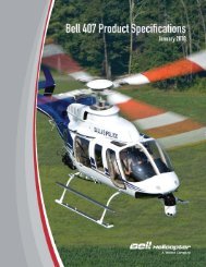
World’s Most Advanced Light TwinCertified for Single or Dual Pilot IFR, Cat. A at MGW 1Certified to FAR Part 27, Amendment 44, 2008Latest Safety Requirements:• Transport Canada (TC)• United States Federal Aviation Administration(FAA)• European Aviation Safety Agency (EASA)State of the Art Glass CockpitBest in Class WAAS Navigation & IFR Capability• Safer fl ights in rigorous IFR fl ightenvironments• greater situational awareness• decreased pilot workload• Fully coupled 4-axis autopilot integration toexecute LPV (Localizer Precision withVertical guidance) approaches• up to and including 9 degree glide pathangle• at speeds down to 45 KIAS• Enables fl ight on WAAS (Wide Area Augmentation System) enabled low-level IFR rotorcraftinfrastructuresFast Flexible Re-configuration for Changing Mission Requirements:• Largest cabin in class, 204 ft 3 / 5.78 m 3• Open cabin with fl at fl oor• 6 passenger std cabin seating with individual quick release for each seat• 62 inch / 159 cm wide cabin door opening• Optional rear clamshell doorsFirst Helicopter certified through the MSG-3 Process (Maintenance Steering Group-3) for enhancedmaintenance efficiency and safety:• First rotorcraft to have an approved EASA Maintenance Program• Ensures Continuing Airworthiness – How and when maintenance will be performed• Benefi ts show in signifi cantly lower maintenance costs• Same systems level maintenance and safety standards used in latest product development by majorlarge commercial aircraft OEM’s.1Category A Operations require installation of the following optional accessory kits:• 200 Amp Starter Generators• Increased Capacity Battery (53 AmpH or 44 AmpH)• Articulated Landing Light• Radar AltimeterSpecifications subject to change without notice.Bell 429 Product Specifi cation 3 Rev. 5 - October 2010
Specification Summary (U.S. Units)Weight LBS Weight LBSEmpty Weight (Std.Confi g.) 1 4,487 lb Max Gross Weight (Internal) 7,000 lbUseful Load (Internal, Std Config.) 2,513 lb Max Gross Weight (External Load) 7,500 lbMinimum Empty Weight (SPIFR) 2 4,247 lb Cargo Hook Capacity 3,000 lbMax Useful Load (Internal, SPIFR)2,753 lbPerformance Summary:Takeoff, Gross Weight lbs 5500 6000 6500 7000IGE Hovering Ceiling ISA ft 20,000+ 18,577 16,301 14,132ISA+20 ft 17,969 15,487 13,102 10,839OGE Hovering Ceiling ISA ft 18,390 15,888 13,535 11,282ISA+20 ft 15,347 12,744 10,287 7963Service Celing (MCP) - AEO ISA ft 20,000+ 20,000+ 20,000+ 18,714(30 minute) - OEI ISA ft 16,690 14,209 11,871 9629(continuous) - OEI ISA ft 15,670 13,153 10,728 8443Maximum Cruise Speed (true airspeed) SL, ISA ktas 154 153 152 150SL, ISA+20C ktas 154 153 151 1494000 ft, ISA ktas 155+ 155+ 155+ 1554000 ft, ISA+20C ktas 153 151 149 145Cruise at Long Range Cruise (LRC) SpeedRange (standard fuel, no reserve) SL, ISA nmi 246 376 378 368LRC Speed (average true airspeed) ktas 128 128 129 130Range (standard fuel, no reserve) 4000 ft, ISA nmi 271 413 414 407LRC Speed (average true airspeed) ktas 128 129 130 129Endurance at Loiter Speed (60 kts) SL, ISA hr 2.8 4.2 4.2 4.0(standard fuel, no reserve) 4000 ft, ISA hr 3.0 4.6 4.5 4.4Engine Ratings: (100% RPM)UninstalledThermodynamic PowerEngine Rated PowerPratt & Whitney Canada PW207D1 with Full Authority Digital ElectronicControl (FADEC)Takeoff (5 minutes) SHP 2 x 719 2 x 598Max Continuous Power SHP 2 x 635 2 x 586OEI (30 seconds) SHP 1 x 826 1 x 729OEI (2 minutes) SHP 1 x 784 1 x 701OEI (30 minutes) SHP 1 x 753 1 x 663OEI (continuous) SHP 1 x 719 1 x 655Transmission Ratings: (100% RPM)Takeoff (5-minute) SHP 1100Max Continuous SHP 1100OEI (30 seconds) SHP 729OEI (2 minutes) SHP 650OEI (30 seconds & continuous) SHP 550Fuel Capacity (usable):Standard216.9 US GallonsAuxiliary (optional)39.2 US GallonsNote 1 Standard Confi guration includes all items listed in the Standard Confi guration section of this document as well as 24 pounds of engine oil.Ballast is not included in the standard configuration (ballast is a function of installed equipment). Also, see Note 1 on page 15.Note 2 See Note 2 on page 15.The data set forth on this document are general in nature and may vary with conditions.For performance data and operating limitations for any specifi c fl ight mission, reference must be made to the approved Flight ManualRev. 5 - October 2010 4 Bell 429 Product Specifi cation
Specification Summary (Metric Units)Weight KG Weight KGEmpty Weight (Std.Confi g.) 1 2,035 kg Max Gross Weight (Internal) 3,175 kgUseful Load (Internal, Std Confi g.) 1,140 kg Max Gross Weight (External Load) 3,402 kgMinimum Empty Weight (SPIFR) 2 1,926 kg Cargo Hook Capacity 1,361 kgMax Useful Load (Internal, SPIFR)1,249 kgPerformance Summary:Takeoff, Gross Weight KG 2495 2722 2948 3175IGE Hovering Ceiling ISA m 6096+ 5662 4969 4307ISA+20 m 5477 4720 3993 3304OGE Hovering Ceiling ISA m 5605 4843 4125 3439ISA+20 m 4678 3884 3135 2427Service Celing (MCP) - AEO ISA m 6096+ 6096+ 6096+ 5704(30 minute) - OEI ISA m 5087 4331 3618 2935(continuous) - OEI ISA m 4776 4009 3270 2573Maximum Cruise Speed (true airspeed) SL, ISA km/hr 285 283 281 278SL, ISA+20C km/hr 285 283 280 2761220 m, ISA km/hr 287+ 287+ 287+ 2871220 m, ISA+20C km/hr 283 280 276 269Cruise at Long Range Cruise (LRC) SpeedRange (standard fuel, no reserve) SL, ISA km 456 696 700 682LRC Speed (average true airspeed) km/hr 237 237 239 241Range (standard fuel, no reserve) 1220 m, ISA km 502 765 767 754LRC Speed (average true airspeed) km/hr 237 239 241 239Endurance at Loiter Speed (111 km/hr) SL, ISA hr 2.8 4.2 4.2 4.0(standard fuel, no reserve) 1220 m, ISA hr 3.0 4.6 4.5 4.4Engine Ratings: (100% RPM)UninstalledThermodynamic PowerEngine Rated PowerPratt & Whitney Canada PW207D1 with Full Authority Digital ElectronicControl (FADEC)Takeoff (5 minutes) kW 2 x 536 2 x 446Max Continuous Power kW 2 x 473 2 x 437OEI (30 seconds) kW 1 x 616 1 x 544OEI (2 minutes) kW 1 x 585 1 x 523OEI (30 minutes) kW 1 x 561 1 x 494OEI (continuous) kW 1 x 536 1 x 488Transmission Ratings: (100% RPM)Takeoff (5-minute) kW 820Max Continuous kW 820OEI (30 seconds) kW 544OEI (2 minutes) kW 485OEI (30 seconds & continuous) kW 410Fuel Capacity (usable):Standard821.1 LitersAuxiliary (optional)148.4 LitersNote 1 Standard Confi guration includes all items listed in the Standard Confi guration section of this document as well as well as 11 kilograms ofengine oil. Ballast is not included in the standard confi guration (ballast is a function of installed equipment). Also, see Note 1 on page 15.Note 2 See Note 2 on page 15.The data set forth on this document are general in nature and may vary with conditions.For performance data and operating limitations for any specifi c fl ight mission, reference must be made to the approved Flight ManualBell 429 Product Specifi cation 5 Rev. 5 - October 2010
Bell BasiX-Pro® Integrated Avionics SystemThe Bell BasiX-Pro® Avionics System has been specifi cally designed to meet the requirements of twin enginehelicopters and is optimized for IFR, Category A, and JAROPS-3 compliant operations. The system is highlyfl exible and confi gurable to meet various operating and customization needs. The system takes advantageof the latest in display, computer processing, and digital data bus technology to provide a high degree ofredundancy, reliability, and fl exibility.Standard Configuration SPIFRThe primary components of the Bell BasiX-Pro® Avionics System in the Bell-429 include the following:Two Multi-FunctionDisplay Units (DUs) with6 x8 inch high-resolutiondisplays.Dual Channel AircraftData Interface Unit(ADIU)Dual Digital 3-axisAutomatic Flight ControlSystem (AFCS)Dual Channel AirData Attitude HeadingReference System(ADAHRS)Course/Heading/FlightDirector Panel (CHFD)The standard confi guration for the Bell Model 429 provides single-pilot IFR capability with 3-axis stability andcontrol augmentation (SCAS) and a coupled fl ight director capability. All Engine Indication and Crew AlertingSystem (EICAS) display functions are provided through the Bell BasiX-Pro® Avionics System. The systemworks in conjunction with the engine control units (EECs) for the dual Pratt & Whitney electronically-controlledPW-207D1 engines. Other aircraft systems interfaces, warnings, cautions, aural alerts, and automatedperformance features are provided through the remotely located Aircraft Data Interface Unit (ADIU).Specifications subject to change without notice.Rev. 5 - October 2010 6 Bell 429 Product Specifi cation
COMMUNICATIONS & NAVIGATION -- The Bell 429 standard confi guration for Communications Navigationand Surveillance (CNS) consists of dual Garmin GNS-430W NAV/COM/WAAS GPS systems, with a kit optionto replace one of these with a GNS-530W. The standard system also includes a GTX-330 ELS compliantMode S transponder, a PMA-7000H Audio/Intercom Panel with VOX and Integral Marker Beacon Receiver,and an ARTEX C406-N-HM Emergency Locator Transmitter (ELT).DISPLAY UNITS -- The Multi-Function display units are “smart displays”, and include all of the processingrequired to collect sub-system information and generate display formats and graphics for the following:• All primary fl ight and navigation instrumentation• Presentation of fl ight director and autopilot status• Engine and rotor drive system indications• Electrical, hydraulic, and fuel system monitoring• Crew alerting system (warnings/cautions/advisories and aural alerts)• Navigation route mapping display• Presentation of optional Traffi c Collision Avoidance Symbology (TCAS)• Presentation of optional weather radar or search radar information• Presentation of optional FLIR/EVS video display (NTSC or PAL standard)• Presentation of general color video display or digital map display (NTSC or PAL standard in eitherS-Video or Component RGB video)• Presentation of electrical, AFCS, and fuel/weight and balance synoptic information• Presentation of automated power assurance, Category A performance, and hover performancecalculations• Presentation of maintenance and diagnostic dataAutomatic Flight Control SystemAMAA-2210-000001Specifications subject to change without notice.Bell 429 Product Specifi cation 7 Rev. 5 - October 2010
Bell BasiX-Pro® Integrated Avionics SystemConfiguration Flexibility to Meet Operational NeedsThe Basix-Pro® includes built-in provisions to allow customized confi guration of the following equipment:• Alternate FMS/GPS systems• Alternate ARINC-429 radio navaids• U/VHF Direction Finder or 2nd ADF• Weather/Search Radar• FLIR/EVS display (NTSC or PAL standard)• Designator Control Panel (allows FLIR or radar cursor designated positions to be captured as waypoints)• General color video display or digital map display• Velocity Sensor (for hover cues and/or search and rescue approach options)• Programmable CAS messages (cautions/warnings/advisories)A third display unit for the copilot position is available for the 429 as an optional accessory.Specifications subject to change without notice.Rev. 5 - October 2010 8 Bell 429 Product Specifi cation
Safety EnhancementsBell is at the forefront in providing multiple ways of satisfying evolving requirements in helicopter traffi cmanagement, fl ight following and terrain awareness safety. The Bell 429 is the fi rst helicopter in the lighttwin category to provide fully-coupled steep (i.e. 9-degree) LPV WAAS approaches. The Bell BasiX-Pro®Integrated Avionics System concentrates on providing true operational capabilities and fl exibility to ourcustomers to address rapidly changing regulatory requirements and technologies, with an open architectureand fl exible avionics systems solutions.The enhancements available for the Bell 429 through optional accessory kits and customizing include:Traffic Advisory System (TAS):Two TAS systems available:• Avidyne TAS605 (recommended), features 13 nm range; 5,500 ft vertical separation; and 55,000 ftservice ceiling• Upgradable to Avidyne TAS605A for ADS-B• Avidyne TAS620, features a 21 nm range, 9,900 foot vertical separation maximum, and 55,000 footservice ceiling• Upgradable to Avidyne TAS620A for ADS-BHelicopter Terrain Awareness and Warning System / Enhanced Ground Proximity Warning System:Three H-TAWS and EGPWS H-TAWS options available• Garmin GNS-530W with H-Taws: Class B H-TAWS system, available as an option on the GNS-530W NAV/COM/GPS with Garmin system software 4.0 roll-out• Light weight, lowest cost solution• Displays on GNS-530W only• Honeywell Mark XXI EGPWS H-TAWS: Class B H-TAWSsystem available as customizing• Installation with or without weather radar• Displays on BasiX-Pro® Display Units, underlaid on PFDHSI format or MFD Map/Radar formatGarmin GNS-530W with H-Taws• Uses same input as weather radar• Provides only oneTAWS image (onerange setting only)• Honeywell Mark XXIIEGPWS H-TAWS:Class A H-TAWSsystem available ascustomizing, adds thefollowing features• Interfaces with ADCand Rad Alt• Provides dualTAWS images withH-TAWS Displays “Under Glass”independent rangeAvailable with Either Mark XXI or XXII EGPWS H-TAWScontrolSpecifications subject to change without notice.Bell 429 Product Specifi cation 9 Rev. 5 - October 2010
Bell 429 External Dimensions and Heliport Design DataLanding Gear Loading at Maximum Gross Weight (7000-Pounds),Based on 1G Static Conditions for both Structural CG LimitCG PositionLoading (lbs) Contact Area (in 2 ) Contact Pressure (lbs/in 2 )FWD AFT FWD AFT FWD AFTFWD CG 3327 3673 5.4 in 2 x 2 9.9 in 2 x 2 308 186AFT CG 2306 4694 5.4 in 2 x 2 9.9 in 2 x 2 214 237Rev. 5 - October 2010 10 Bell 429 Product Specifi cation
429 InteriorCREW SEATING – Two individual ergonomically designed energy attenuating seats with adjustable lumbarsupport, each equipped with seat adjustment controls forward and aft, up and down, adjustable lumbar support,a four-point restraint system, and adjustable pedals. The color and upholstery material for the seats match thecolor scheme selected for the cabin.PASSENGER/CARGO COMPARTMENT – The passenger/cargo compartment occupies the middle sectionof the cabin. The compartment has a volume of 130 cubic feet (3.68 m 3 ), which can be used in a standard orcorporate confi guration for passenger seating, or as cargo area. The aft cabin has an additional volume of 74cubic feet (2.10 m 3 ), giving a total contiguous cabin volume of 204 cubic feet (5.78 m 3 ).A forward hinged and aft sliding door on each side of the cabin provide a 61.9” wide x 44.25” high (158.7 x112.3 cm) unobstructed door opening on each side of the helicopter for easy passenger compartment loadingand unloading. The two forward doors are hinged to open forward and the two sliding doors open aft and fl ushalong the cabin exterior. The passenger/cargo compartment doors can be opened individually or at the sametime.Specifications subject to change without notice.Bell 429 Product Specifi cation 11 Rev. 5 - October 2010
STANDARD SEATING AND TRIM – Standard Confi guration six-place seating consists of two rows of threeenergy-absorbing seats, with individual 4-point restraint system, quick release disconnects and fi xed provisionsfor the optional passenger cabin ICS system. Two standard seating confi gurations are available:• 6-place seating with 15.5“ wide seats, which can be quickly arranged into either an airline confi gurationwith both rows facing forward, or a club seating confi guration with two rows facing each other• 6-place seating with 18.5” wide seats in a club seating confi guration.Each individual passenger seat assembly is installed on two transverse seat rail tracks that are attached to thecabin fl oor. The quick release disconnects enable the seats to be quickly arranged, or to remove individualseats to meet special mission confi guration requirements. The seats are upholstered in fabric or optional vinyl.Standard interior trim consists of full thermoplastic closeouts on all airframe areas, a molded thermoplasticheadliner with two fi xed slotted air vents, and a choice of either durable low loop nylon blend carpeting oroptional “Aermat” vinyl fl oor covering.Standard 6-place 15.5” wide passenger seats in ForwardFacing Airline Seating ArrangementStandard 6-place 18.5” wide passenger seats in ClubSeating ArrangementStandard Headliner with slotted air ventsOptional Headliner with LED lights& adjustable air ventsADDITIONAL INTERIOR OPTIONS – The following additional optional accessory kits are also available forselection on aircraft equipped with standard interior and seating. See Optional Accessory Kits, page 18 foradditional information on part numbers, availability and weights.• Aft Cabin ICS – 6 Place (Headsets not included)• Headliner with LED lights & adjustable Air Vents (recommended when optional air conditioningequipment is selected)• Soundproofi ng• Aft Bulkhead Closeout Panel, available with or without soundproofi ngSpecifications subject to change without notice.Rev. 5 - October 2010 12 Bell 429 Product Specifi cation
CORPORATE SEATING AND INTERIOR TRIM:Three corporate seating options are available:Six place seating with 18.5” wide seatsAll corporate seating options include plush “OverstuffedStyle” seats with individual 3-point restraint system, quickrelease disconnects and fi xed provisions for a passengercabin ICS system. For the fi ve place club seating option,the quick release disconnects enable the seats to bequickly arranged with the two 21.5” seats facing eitherforward or aft. The seats are upholstered in premiumleather.The corporate interior trim consists of full thermoplasticpanels on all airframe areas with color coordinated leatheror fabric trim, plush wool color coordinated carpet, and amolded thermoplastic corporate headliner with LED lights,adjustable air vents and color coordinated leather trim.Five place club seating with a row of two 21.5” seatsseparated by a center console facing a row ofthree 18.5” seats with a center seat fold-down tableADDITIONAL INTERIOR OPTIONS – The followingadditional optional accessory kits are also available forselection on aircraft equipped with a corporate interiorand seating.• Aft Cabin ICS – 6 Place (Headsets not included)• Soundproofi ng• Aft Bulkhead Closeout Panel, available with orwithout soundproofi ng• 6-place 18.5” corporate seats with fold-down centertables as a customizing optionFour place club seating with two 21.5” seatsseparated by a center console in each rowNote: Corporate passenger seats, interior trim andplush wool carpeting, corporate head liner, aftbulkhead closeout panel, and soundproofi ngare optional accessory kits, not included inStandard Confi guration weight and price.See Optional Accessory Kits, page 18, foradditional information.A molded thermoplastic corporate headliner withLED lights, adjustable air vents and colorcoordinated leather trimSpecifications subject to change without notice.Bell 429 Product Specifi cation 13 Rev. 5 - October 2010
Standard Configuration(Items Included in List Price)Certified for Single Pilot IFRCertification Basis: FAR Part 27 Amendment 44, 2008(Most current Certification Standard)AIRFRAMEFuselage: Machined alloy airframe with single piecemachined roof beams, lift frames, cabin keel beams and nosebeams; carbon fi ber composite side-bodies, belly panels, noseskins, fl oor panels, decks and engine cowlsCorrosion resistant design with wet installed fasteners andsealed surfaces where dissimilar materials are found toprovide exceptional resistance to adverse environmentalconditionsDoors (six, carbon fi ber): Hinged pilot & co-pilot doors withsliding windows; hinged forward and sliding aft passengerdoors on both sides.Passenger doors provide 61.9 inches unobstructed openingon each side.Door Locks for cabin doors and luggage compartmentLuggage compartment: Aft cabin (74 cubic feet), with 16discrete tie-down hardpoints and R/H side external luggagedoorLanding gear: Tubular skid type with replaceable wear shoesTailboom: Carbon fi ber tailboom, vertical fi n and horizontalstabilizerFuselage mounted passenger cabin steps, forward mountedcrew steps, and aft maintenance stepProvisions for mooring, jacking and single point liftingWindows: Gray tinted acrylic windows and windshieldsWire Strike Protection System Fixed Provisions , Cabin andNose Provisions (Bristol/AAI)Air Conditioning Drive Quill (Required for installation of any AirConditioning system)Air Conditioning Fixed ProvisionsThree color exterior paint schemes, Sample illustrationsavailable upon requestPOWERPLANTTwo Pratt & Whitney Canada 207D1 Engines, 1,172 shp,(Mechanical) Maximum Continuous Rating (586 shp perengine)Electronic Engine Controls (EEC)Fuel Management Module (FMM)Fuel system: 216.9 gal. (821 liter) usable capacity, with threerupture resistant fuel cells located under the cabin fl oor paneland suction-type fuel feed systemElectrical Provisions for Inlet Barrier FilterEngine Fire Detector & Fire Extinguisher SystemTRANSMISSION AND DRIVE SYSTEMSTwo-stage dual input drive main transmission, 1,100 shpMaximum Continuous PowerTwo fl uid fi lled pylon mounts LIVE suspension (left and rightvertical axis mounts)Two elastomeric forward/aft restraintsThree main transmission chip detectorsTwo transmission-mounted hydraulic pumpsTail rotor drive shaft:Two steel forward drive shafts in engine deck/fi re zoneTwo interchangeable carbon fi ber composite aft driveshafts in tailboom zoneSingle stage 90 O tail rotor gearboxOne tail rotor gearbox chip detectorROTORS AND CONTROLSMain rotor: Soft-in-plane system, 36 ft. diameter, fourinterchangeable M/R blades, with stacked composite yokes,titanium drive plate and CF fi ttings, elastomeric CF bearingsand shear restraints, and elastomeric lead/lag dampersComposite M/R blades with Nickel-Cobalt leading edgeabrasion strips and tip caps, HIGH VISABILITY (orange/whitetop - white bottom) paint schemeTail rotor: Four blade stacked system, 65” diameter, with lowtip speed, scissor arrangement, composite T/R blades withswept blade tips, Nickel-Cobalt leading edge abrasion strips,and elastomeric fl apping bearingsDual Hydraulic System with integrated hydraulic modulesMechanical fl ight controls throughoutCollective mounted throttle controlsRotor Brake ProvisionsFLIGHT & ENGINE INSTRUMENTS – Bell BasiX-ProIntegrated Avionics SystemEFIS/EICAS (Electronic Flight Instruments System/ EngineIndicating & Crew Alerting System)Two 6” x 8” color LCD displays with video display capability“Smart” programmable display unit provisions for futureinterface required for customized equipment installationsAircraft Data Interface Unit, Dual ChannelAFCS (3-axis), Dual digital autopilotDual channel SCAS and trim actuatorsAD/AHRS (Air Data/Attitude Heading Reference System),Dual Channel (Honeywell KSG7200)Course/Heading/Flight Director PanelSpecifications subject to change without notice.Rev. 5 - October 2010 14 Bell 429 Product Specifi cation
Standard Configuration (cont)(Items Included in List Price)Certified for Single Pilot IFRCertification Basis: FAR Part 27 Amendment 44, 2008(Most current Certification Standard)Standby Instruments: Attitude, Altitude, Heading and AirspeedElectronic Data Recorder embedded in the IAS (IntegratedAvionic System) (non-crashworthy)COMMUNICATIONS & NAVIGATIONNav/Comm/GPS: VOR/ILS/GS/COMM/GPS and WAAS(Wide Area Augmentation System), with two 1.8”h x 3.3”w”displays (Garmin GNS 430W)Transponder: ELS compliant Mode S (Garmin GTX 330)Dual Keyed and/or VOX Intercom SystemPMA-7000H Audio Panel with Integral Marker BeaconReceiverELT (ARTEX C406-N-HM)INTERIOROpen cabin design with fl at fl oor, total contiguous cabinvolume 232 cu. ft. (passenger and aft cabin area volume 204cu. ft.)Standard cockpit seating (2 seats), adjustable forward & aft,up & down, with lumbar support and adjustable pedalsPassenger Seat RailsStandard 6-place passenger seating with 4-point restraintsystem, quick release disconnects & ICS fi xed provisions(choice of 15.5” wide seats or 18.5” wide seats)Ram air cockpit and cabin ventilation systemStandard Interior (Thermoplastic panels covering all doors &durable low loop nylon carpet or “Aermet” vinyl fl oor covering)Standard Headliner, Passenger Cabin, with two fixed slottedside air ventsNote: Additional Passenger Cabin interior, headliner andseating options available for the 429 are listed in theOptional Accessory Kits section.ELECTRICAL28 volt DC system, dual generator confi guration25 AmpH Valve Regulated Lead-Acid (VRLA) BatteryTwo 150 Amp Starter Generators, with two generator-regulatorcontrol unitsExternal power source connectionLED Cockpit instrument, annunciator, utility and map lightingwith programmable lighting power supply to ensure lightbalancing across all cockpit display and control panelsAll LED basic external lighting system:• One forward & two sideward facing fi xed LED arraylanding lights• Three high intensity LED position lights• One fl ashing LED anti-collision lightDigital maintenance interface available from cockpit for alldigital aircraft systemsRADS wiring for sensors embedded in basic aircraft wiringBaggage compartment lightingElectrical Provisions Kit (Required for Cat. A Operations)MISCELLANEOUSKeys for crew, passenger and baggage compartment doorsManuals – Flight, Maintenance and Illustrated PartsBreakdown/Special Tools CatalogueMain and tail rotor tie downsCargo tie downs (loose equipment)Covers – engine air, oil cooler, exhaust and pitotGround handling wheels, hydraulicReference notes from pages 4-5Note 1 Standard Confi guration includes:• Provisions for optional equipment including Cat. A Operations, Inlet Barrier Filter, Air Conditioning, Rotor Brake & WireStrike Protection System• ELT• Pilot & Copilot seats• 6 place Passenger Seating with 18.5” wide seats• Standard Interior, Headliner panels and CarpetNote 2 Minimum SPIFR Confi guration includes:• Provisions for optional equipment including Cat. A Operations, Inlet Barrier Filter, Air Conditioning, Rotor Brake & WireStrike Protection System• ELT• Pilot seatSpecifications subject to change without notice.Bell 429 Product Specifi cation 15 Rev. 5 - October 2010
Optional Accessory KitsRefer to notes for kit compatibility.Additional Kits and STC Items may be available for factory installation.Please consult sales or contract personnel regarding special needs prior to selection of fi nal confi gurationKit DescriptionPart NumberProjectedAvailabilityStatusAIRFRAMEDual Pilot Control Provisions 429-706-701-103 5.3 2.4 3Dual Pilot Controls Equipment (does not include co-pilothead set) (Required for Dual Pilot operation)429-706-701-101 10.5 4.8 3Pilot Cyclic Stick Locking Device 429-706-704-101 0.2 0.1200 Amp Starter Generator (Dual)(Required for Cat. A Operations)429-706-020-101 7.8 3.5 1, 18Increased Capacity Battery, 53 AmpH (Cat. A Compliant) 429-706-025-101 35.1 15.9 1, 18Increased Capacity Battery, 44 AmpH (Cat. A Compliant) 429-706-025-103 28.2 12.8 1, 1836 AmpH Battery 429-706-025-105 19.1 8.7 1, 18Articulated Landing Light (Required for Cat. A Operations)429-706-027-101Effectivity: s/n 57001 9.2 4.2 1- 57017Articulated Landing Light (Required for Cat. A Operations)429-706-027-103Effectivity: s/n 57018 9.2 4.2 1& subsequentRotor Brake Equipment 429-706-702-101 9.8 4.4Aux. Fuel Tank Equipment (39 US Gal.) 429-706-500-101 60.2 27.3Windshield Wiper (Pilot) 429-706-030-101 9.5 4.3Windshield Wiper (Co-pilot) 429-706-030-103 6.7 3.0Rear Clamshell Doors with windows429-706-002-101Effectivity: s/n 57001 29.3 13.3- 57016Rear Clamshell Doors with windows429-706-002-103Effectivity: s/n 57017 28.8 13.1& subsequentEmergency Float Provisions (Electrical & Fixed)429-706-069-107 &429-706-069-1094th Qtr 2010 2.0 0.9 4Emergency Floats without life rafts (Aerazur) (life vests notincluded)429-706-069-101 4th Qtr 2010 143.6 65.1 4Emergency Floats with one life raft, Left side (Aerazur) (lifevests not included)429-706-069-103 4th Qtr 2010 189.3 85.9 4Emergency Floats with two life rafts, Left & Right sides(Aerazur) (life vests not included)429-706-069-105 4th Qtr 2010 235.0 106.6 4Life Vest Provisions, 4 place Stowage Pouches 429-706-070-101 0.6 0.3 5Life Vest Provisions. 5 place Stowage Pouches 429-706-070-102 0.7 0.3 5Life Vest Provisions, 6 place Stowage Pouches 429-706-070-103 0.8 0.4 5Ditching Kit (additional strengthening to a/c nose and belly) 429-706-048-101 4th Qtr 2010 3.2 1.5 5Emergency Egress, Standard Interior (push-out windowsfor hinged passenger doors)429-706-068-101 4th Qtr 2010 8.1 3.7 6Protected Tail-Rotor System 429-706-066-101 4th Qtr 2010 10.2 4.6 7AUDIOAft Cabin ICS - 6 Place (Headsets not included) 429-706-045-101 2.5 1.1Wt(lbs)Wt(kg)NotesSpecifications subject to change without notice.Rev. 5 - October 2010 16 Bell 429 Product Specifi cation
Optional Accessory Kits (con’t)Kit DescriptionAVIONICSRadar Altimeter (Honeywell KRA 405B) (Required for Cat.A Operations)3rd Display Unit & 2nd Standby Compass (Required forDual Pilot IFR)3rd Display Unit & 2nd Standby Compass (Required forDual Pilot IFR)Part NumberProjectedAvailabilityStatusWt(lbs)Wt(kg)Notes429-706-042-101 5.5 2.5 1429-706-026-101Effectivity:s/n 57001 - 57026429-706-026-103Effectivity: s/n 57027& subsequent 23.6 10.7 3 23.6 10.7 3ADF (Honeywell KR 87) 429-706-043-101 9.8 4.4GNS-530W NAV/COMM/GPS (replaces StandardEquipment #1 GNS-430W )429-706-021-103 2.2 1.0Traffi c Advisory System (Avidyne TAS620) 429-706-017-101 17.7 8.0 8Traffi c Advisory System (Avidyne TAS605)Available ascustomized installation 8.3 3.8 84th Axis Autopilot 429-706-703-103 4.5 2.0Weather Radar (Primus 660) 429-706-018-101 24.5 11.1ENGINEEngine Fuel Heater (PW207D2 Engine) (P&W)Available ascustomized installation 4.3 2.0Compressor Wash Kit 429-706-047-101 1.4 0.6Inlet Barrier Filter 429-706-300-101 20.5 9.3Engine Fire Extinguisher - 2nd bottleENVIRONMENT429-706-041-101Effective s/n 57015& sub 6.8 3.1Single Evaporator Air Conditioning with manual controls 429EC-202-1 84.5 38.3 9, 10Dual Evaporator Air Conditioning with manual controls 429EC-200-1 113.3 51.4 9, 10Bleed Air Heater Provisions 429H-224-1 16.6 7.5Bleed Air Heater Equipment (with chin bubble defrost) 429H-238-1 21.1 9.6EQUIPMENTCargo Hook Provisions (Onboard Systems) 429-706-009-103 11.6 5.3Cargo Hook Equipment, 3,000 lb. capacity (OnboardSystems)429-706-009-101 31.4 14.2High Gross Weight Towing kit (AAI) 429-604-001 N/A N/AMain Rotor Blade Folding Kit (2 - fwd, 2 - aft) (Paravion) 429BF-900-1 TBD 1.0 0.5Rescue Hoist Provisions 429-705-005-101 1st Qtr 2011 35.4 16.111, 19,20Rescue Hoist Equipment, Goodrich 600 lb. capacity 429-706-001-101 1st Qtr 2011 184.2 83.6 11FLIGHT & ENGINE INSTRUMENTSCockpit Voice Recorder/Flight Data Recorder, Crashworthy 429-706-058-101 4th Qtr 2010 14.1 6.4Health & Usage Monitoring System (AAI) 429-260-001 4th Qtr 2010 18.0 8.2NVG Compatible Pilot Display Units and Flight Director(US ITAR Controlled)429-706-022-101Effective s/n57007-57026 0.5 0.2 12Specifications subject to change without notice.Bell 429 Product Specifi cation 17 Rev. 5 - October 2010
Optional Accessory Kits (con’t)Kit Description3rd Display Unit and 2nd Standby Compass with NVGcompatible 3rd Display Unit (US ITAR Controlled)NVG Compatible Pilot Display Units and Flight Director(US ITAR Controlled)3rd Display Unit and 2nd Standby Compass with NVGcompatible 3rd Display Unit (US ITAR Controlled)NVG compatible lighting for other light sources (US ITARControlled)INTERIORHeadliner with LED lights & adjustable Air ConditioningventsCorporate Headliner with LED lights, adjustable AirConditioning vents and color coordinated leather trimCorporate Interior, Single Pilot:• Corporate Interior Trim• Plush Wool Carpets (for use with Single Pilot controls)Corporate Interior, Dual Pilot:• Corporate Interior Trim• Plush Wool Carpets (for use with Dual Pilot controls)Part Number429-706-022-103Effective s/n57007-57026429-706-022-105Effective s/n 57027& sub429-706-022-107Effective s/n 57027& subAerodynamix STCProjectedAvailabilityStatusWt(lbs)Wt(kg)Notes 0.0 0.0 12 0.0 0.0 12 0.0 0.0 12Available ascustomizedinstallationTBD TBD 12429-706-202-103 18.9 8.6 10429-706-202-105 19.1 8.7 10429-706-201-103 &429-706-033-103429-706-201-103 &429-706-033-101 10.3 4.7 14 9.3 4.2 14Cabin Soundproofi ng 429-706-034-101 10.0 4.5 13Aft Bulkhead Closeout panel 429-706-060-103 9.6 4.4 11, 13Aft Bulkhead Closeout panel with soundproofi ng 429-706-060-105 26.5 12.0 11, 13Available asUtility Light Weight Interior-20.0 -9.1customized installationNote: All interior option weight values are weight increase or decrease from the standard confi guration weights.PASSENGER SEATING OPTIONSCorporate 6-Place Seating, 18.5” wide seats with 3-pointrestraint system, quick release disconnects & ICS fi xed 429-706-010-105 25.2 11.4provisions.Corporate 5-Place club seating with 1 centre console andside arm rests, 3-point restraint system, quick release 429-706-010-107 34.0 15.4disconnects & ICS fi xed provisions.Corporate 4-Place club seating with centre consoles andside arm rests, 3-point restraint system, quick release 429-706-010-109 35.5 16.1disconnects & ICS fi xed provisions.Seat Rail Removal 429-706-024-101 -6.0 -2.7 2, 17Note: All passenger seating option weight values are weight increase or decrease from the standard confi guration weights.VENDOR KITS - STCSliding Passenger Door Photo (Sliding) Window, L/H (AAI) See Note 15 4.4 2.0 15Sliding Passenger Door Photo (Sliding) Window, R/H(AAI)See Note 15 4.4 2.0 15Automatic Door Openers, Crew (2 door kit) (AAI) 429-510-001 2.0 0.9Automatic Door Openers, Passenger (2 door kit) (AAI) 429-510-002 2.2 1.0Specifications subject to change without notice.Rev. 5 - October 2010 18 Bell 429 Product Specifi cation
13. For effective internal noise reduction, Aft Cabin Bulkhead panel, p/n 429-706-060-103 or 429-706-060-105, is stronglyrecommended when cabin soudproofi ng is installed.14. Standard Confi guration fl oor covering includes a customer choice of materials, either durable low loop nylon blend carpet or“”Aermat”” vinyl fl oor covering. Either single pilot or dual pilot standard carpet is included in Standard Confi guration Price.Corporate Interior fl oor covering is plush 100% wool carpet, colour coordinated to match leather seat upholstery.15. Three Passenger Door Sliding Window colour options available:p/n 429-564-007, L/H (Gray)p/n 429-564-009, L/H (Medium Gray)p/n 429-564-011, L/H (Dark Gray)p/n 429-564-008, R/H (Gray)p/n 429-564-010, R/H (Medium Gray)p/n 429-564-012, R/H (Dark Gray)16. Wire Strike Protection System Provisions are included in Standard Configuration.17. Passenger Seat Rail Removal kit required for installation of AMC or Aerolite EMS Interior Systems.18. Installation of 53 AmpH, 44 AmpH or 36 AmpH battery requires installation of the 200 Amp Starter Generator kit. However,installation of 200 Amp Starter Generator does not require installation of the 53 AmpH battery.19. Rescue Hoist Provisions cannot be installed when Aft Bulkhead Closeout panel is installed.20. Right side aft passenger seat must be removed for installation of the Rescue Hoist Control Box Pendent Bracket. Pendentbracket is removable when pendent is not installed for mission use.Specifications subject to change without notice.Rev. 5 - October 2010 20 Bell 429 Product Specifi cation
Fuel Flow ChartsISA & ISA+20 O CNEW PRATT & WHITNEY CANADA PW207D1/D2 ENGINESBASIC INLET OR BARRIER FILTER INSTALLEDCLEAN CONFIGURATION WITH STANDARD SKID GEARAIR CONDITIONING / HEATER OFFBell 429 Product Specifi cation 21 Rev. 5 - October 2010
Fuel Flow vs AirspeedNew EnginesClean Configuration with Standard Skid GearEngine RPM - 100%Zero WindPressure Altitude = Sea LevelOAT = 15 O C (ISA)TRUE AIRSPEED - KM/HR80 100 120 140 160 180 200 220 240 260 280 300 320680100660640TRANSMISSION LIMIT30029095620280TORQUE - %90858075706560555045403530FUEL FLOW - LB/HR6005805605405205004804604404204003803603403203002802607065605550MAXENDUR.GW x 100 LBLRCV NE270260250240230220210200190180170160150140130120FUEL FLOW - KG/HR40 50 60 70 80 90 100 110 120 130 140 150 160 170 180TRUE AIRSPEED - KNOTS40 50 60 70 80 90 100 110 120 130 140 150 160 170INDICATED AIRSPEED - KNOTSThe data set forth on this document are general in nature and may vary with conditions.For performance data and operating limitations for any specifi c fl ight mission, reference must be made to the approved Flight ManualRev. 5 - October 2010 22 Bell 429 Product Specifi cation
Fuel Flow vs AirspeedNew EnginesClean Configuration with Standard Skid GearEngine RPM - 100%Zero WindPressure Altitude = 2000 FtOAT = 11 O C (ISA)TRUE AIRSPEED - KM/HR80 100 120 140 160 180 200 220 240 260 280 300 320680100660640TRANSMISSION LIMIT300290TORQUE - %95908580757065605550FUEL FLOW - LB/HR620600580560540520500480460440420400MAXENDUR.LRC280270260250240230220210200190180FUEL FLOW - KG/HR454035303803603403203002802607065605550GW x 100 LBV NE17016015014013012040 50 60 70 80 90 100 110 120 130 140 150 160 170 180TRUE AIRSPEED - KNOTS40 50 60 70 80 90 100 110 120 130 140 150 160 170INDICATED AIRSPEED - KNOTSThe data set forth on this document are general in nature and may vary with conditions.For performance data and operating limitations for any specifi c fl ight mission, reference must be made to the approved Flight ManualBell 429 Product Specifi cation 23 Rev. 5 - October 2010
Fuel Flow vs AirspeedNew EnginesClean Configuration with Standard Skid GearEngine RPM - 100%Zero WindPressure Altitude = 4000 Ft.OAT = 7 O C (ISA)TRUE AIRSPEED - KM/HR80 100 120 140 160 180 200 220 240 260 280 300 320680660300TORQUE - %1009590858075706560555045403530FUEL FLOW - LB/HR640620600580560540520500480460440420400380360340320300280260TRANSMISSION LIMIT7065605550MAXENDUR.GW x 100 LBLRCV NE290280270260250240230220210200190180170160150140130120FUEL FLOW - KG/HR40 50 60 70 80 90 100 110 120 130 140 150 160 170 180TRUE AIRSPEED - KNOTS40 50 60 70 80 90 100 110 120 130 140 150 160INDICATED AIRSPEED - KNOTSThe data set forth on this document are general in nature and may vary with conditions.For performance data and operating limitations for any specifi c fl ight mission, reference must be made to the approved Flight ManualRev. 5 - October 2010 24 Bell 429 Product Specifi cation
Fuel Flow vs AirspeedNew EnginesClean Configuration with Standard Skid GearEngine RPM - 100%Zero WindPressure Altitude = 6000 FtOAT = 3 O C (ISA)TRUE AIRSPEED - KM/HR80 100 120 140 160 180 200 220 240 260 280 300 320680660300TORQUE - %1009590858075706560FUEL FLOW - LB/HR640620600580560540520500480460440420TRANSMISSION LIMITMAX CONTINUOUS POWERLRC290280270260250240230220210200190FUEL FLOW - KG/HR5550454035304003803603403203002802605070656055MAXENDUR.GW x 100 LBV NE18017016015014013012040 50 60 70 80 90 100 110 120 130 140 150 160 170 180TRUE AIRSPEED - KNOTS40 50 60 70 80 90 100 110 120 130 140 150 160INDICATED AIRSPEED - KNOTSThe data set forth on this document are general in nature and may vary with conditions.For performance data and operating limitations for any specifi c fl ight mission, reference must be made to the approved Flight ManualBell 429 Product Specifi cation 25 Rev. 5 - October 2010
Fuel Flow vs AirspeedNew EnginesClean Configuration with Standard Skid GearEngine RPM - 100%Zero WindPressure Altitude = 8000 Ft.OAT = -1 O C (ISA)TRUE AIRSPEED - KM/HR80 100 120 140 160 180 200 220 240 260 280 300 320680660300100640620290280TORQUE - %9590858075706560555045403530FUEL FLOW - LB/HR600580560540520500480460440420400380360340320300280260MAX CONTINUOUS POWER6560555070MAXENDUR.GW x 100 LBLRCV NE270260250240230220210200190180170160150140130120FUEL FLOW - KG/HR40 50 60 70 80 90 100 110 120 130 140 150 160 170 180TRUE AIRSPEED - KNOTS40 50 60 70 80 90 100 110 120 130 140 150INDICATED AIRSPEED - KNOTSThe data set forth on this document are general in nature and may vary with conditions.For performance data and operating limitations for any specifi c fl ight mission, reference must be made to the approved Flight ManualRev. 5 - October 2010 26 Bell 429 Product Specifi cation
Fuel Flow vs AirspeedNew EnginesClean Configuration with Standard Skid GearEngine RPM - 100%Zero WindPressure Altitude = 10,000 FtOAT = -5 O C (ISA)TRUE AIRSPEED - KM/HR80 100 120 140 160 180 200 220 240 260 280 300 320680660300100640620290280TORQUE - %9590858075706560FUEL FLOW - LB/HR600580560540520500480460440420400MAX CONTINUOUS POWER270260250240230220210200190180FUEL FLOW - KG/HR5550454035303803603403203002802607065605550MAXENDUR.GW x 100 LBLRCV NE17016015014013012040 50 60 70 80 90 100 110 120 130 140 150 160 170 180TRUE AIRSPEED - KNOTS40 50 60 70 80 90 100 110 120 130 140 150INDICATED AIRSPEED - KNOTSThe data set forth on this document are general in nature and may vary with conditions.For performance data and operating limitations for any specifi c fl ight mission, reference must be made to the approved Flight ManualBell 429 Product Specifi cation 27 Rev. 5 - October 2010
Fuel Flow vs AirspeedNew EnginesClean Configuration with Standard Skid GearEngine RPM - 100%Zero WindPressure Altitude = Sea LevelOAT = 35 O C (ISA+20 O C)TRUE AIRSPEED - KM/HR80 100 120 140 160 180 200 220 240 260 280 300 320100680660TRANSMISSION LIMIT300TORQUE - %9590858075706560555045403530FUEL FLOW - LB/HR640620600580560540520500480460440420400380360340320300280260MAX CONTINUOUS POWER7065605550MAXENDUR.GW x 100 LBLRCV NE290280270260250240230220210200190180170160150140130120FUEL FLOW - KG/HR40 50 60 70 80 90 100 110 120 130 140 150 160 170 180TRUE AIRSPEED - KNOTS40 50 60 70 80 90 100 110 120 130 140 150 160 170INDICATED AIRSPEED - KNOTSThe data set forth on this document are general in nature and may vary with conditions.For performance data and operating limitations for any specifi c fl ight mission, reference must be made to the approved Flight ManualRev. 5 - October 2010 28 Bell 429 Product Specifi cation
Fuel Flow vs AirspeedNew EnginesClean Configuration with Standard Skid GearEngine RPM - 100%Zero WindPressure Altitude = 2000 FtOAT = 31 O C (ISA+20 O C)TRUE AIRSPEED - KM/HR80 100 120 140 160 180 200 220 240 260 280 300 320680TORQUE - %1009590858075706560555045403530FUEL FLOW - LB/HR660640620600580560540520500480460440420400380360340320300280260MAX CONTINUOUS POWER7060555065MAXENDUR.GW x 100 LBLRCV NE300290280270260250240230220210200190180170160150140130120FUEL FLOW - KG/HR40 50 60 70 80 90 100 110 120 130 140 150 160 170 180TRUE AIRSPEED - KNOTS40 50 60 70 80 90 100 110 120 130 140 150 160INDICATED AIRSPEED - KNOTSThe data set forth on this document are general in nature and may vary with conditions.For performance data and operating limitations for any specifi c fl ight mission, reference must be made to the approved Flight ManualBell 429 Product Specifi cation 29 Rev. 5 - October 2010
Fuel Flow vs AirspeedNew EnginesClean Configuration with Standard Skid GearEngine RPM - 100%Zero WindPressure Altitude = 4000 Ft.OAT = 27 O C (ISA+20 O C)TRUE AIRSPEED - KM/HR80 100 120 140 160 180 200 220 240 260 280 300 320680660300100640290TORQUE - %9590858075706560555045403530FUEL FLOW - LB/HR620600580560540520500480460440420400380360340320300280260MAX CONTINUOUS POWER6560555070MAXENDUR.GW x 100 LBLRCV NE280270260250240230220210200190180170160150140130120FUEL FLOW - KG/HR40 50 60 70 80 90 100 110 120 130 140 150 160 170 180TRUE AIRSPEED - KNOTS40 50 60 70 80 90 100 110 120 130 140 150 160INDICATED AIRSPEED - KNOTSThe data set forth on this document are general in nature and may vary with conditions.For performance data and operating limitations for any specifi c fl ight mission, reference must be made to the approved Flight ManualRev. 5 - October 2010 30 Bell 429 Product Specifi cation
Fuel Flow vs AirspeedNew EnginesClean Configuration with Standard Skid GearEngine RPM - 100%Zero WindPressure Altitude = 6000 FtOAT = 23 O C (ISA+20 O C)TRUE AIRSPEED - KM/HR80 100 120 140 160 180 200 220 240 260 280 300 320680660300100640290TORQUE - %9590858075706560555045403530FUEL FLOW - LB/HR620600580560540520500480460440420400380360340320300280260MAX CONTINUOUS POWER6560555070MAXENDUR.GW x 100 LBLRCV NE280270260250240230220210200190180170160150140130120FUEL FLOW - KG/HR40 50 60 70 80 90 100 110 120 130 140 150 160 170 180TRUE AIRSPEED - KNOTS40 50 60 70 80 90 100 110 120 130 140 150INDICATED AIRSPEED - KNOTSThe data set forth on this document are general in nature and may vary with conditions.For performance data and operating limitations for any specifi c fl ight mission, reference must be made to the approved Flight ManualBell 429 Product Specifi cation 31 Rev. 5 - October 2010
Fuel Flow vs AirspeedNew EnginesClean Configuration with Standard Skid GearEngine RPM - 100%Zero WindPressure Altitude = 8000 Ft.OAT = 19 O C (ISA+20 O C)TRUE AIRSPEED - KM/HR80 100 120 140 160 180 200 220 240 260 280 300 320680660300100640290TORQUE - %9590858075706560FUEL FLOW - LB/HR620600580560540520500480460440420MAX CONTINUOUS POWER280270260250240230220210200190FUEL FLOW - KG/HR5550454035304003803603403203002802606055506570MAXENDUR.GW x 100 LBLRCV NE18017016015014013012040 50 60 70 80 90 100 110 120 130 140 150 160 170 180TRUE AIRSPEED - KNOTS40 50 60 70 80 90 100 110 120 130 140 150INDICATED AIRSPEED - KNOTSThe data set forth on this document are general in nature and may vary with conditions.For performance data and operating limitations for any specifi c fl ight mission, reference must be made to the approved Flight ManualRev. 5 - October 2010 32 Bell 429 Product Specifi cation
Fuel Flow vs AirspeedNew EnginesClean Configuration with Standard Skid GearEngine RPM - 100%Zero WindPressure Altitude = 10,000 FtOAT = 15 O C (ISA+20 O C)680TRUE AIRSPEED - KM/HR80 100 120 140 160 180 200 220 240 260 280 300 32066030010064029095620600280270TORQUE - %90858075706560555045403530FUEL FLOW - LB/HR580560540520500480460440420400380360340320300280260MAX CONTINUOUS POWER5550606570MAXENDUR.GW x 100 LBLRCV NE260250240230220210200190180170160150140130120FUEL FLOW - KG/HR40 50 60 70 80 90 100 110 120 130 140 150 160 170 180TRUE AIRSPEED - KNOTS40 50 60 70 80 90 100 110 120 130 140INDICATED AIRSPEED - KNOTSThe data set forth on this document are general in nature and may vary with conditions.For performance data and operating limitations for any specifi c fl ight mission, reference must be made to the approved Flight ManualBell 429 Product Specifi cation 33 Rev. 5 - October 2010
Page Intentionally Left BlankRev. 5 - October 2010 34 Bell 429 Product Specifi cation
Performance ChartsIGE & OGE HOVER AND SERVICE CEILINGSPRATT & WHITNEY CANADA PW207D1/D2 ENGINESMINIMUM SPECIFICATION ENGINE POWERBASIC INLET OR BARRIER FILTER INSTALLEDAIR CONDITIONING / HEATER OFFThe data set forth on this document are general in nature and may vary with conditions.For performance data and operating limitations for any specifi c fl ight mission, reference must be made to the approved Flight ManualBell 429 Product Specifi cation 35 Rev. 5 - October 2010
IGE Hover CeilingTwin Engine Takeoff PowerBasic Inlet or Barrier Filter InstalledRotor RPM = 100%Zero Wind or HeadwindGROSS WEIGHT - 100 KG21 22 23 24 25 26 27 28 29 30 31 32 33 34201918ISA+30°CISA+20°CISA+10°CISA60561752PRESSURE ALTITUDE - 1000 FT1615141312111098765-10°CMAX OAT LIMIT (ISA+36.7°C)30°C20°C10°C-40°C-30°C-20°C0°C40°C484440363228242016PRESSURE ALTITUDE - 100 METERS43210SKID HEIGHT 4 FT (1.2M)46 48 50 52 54 56 58 60 62 64 66 68 70 72 74 76GROSS WEIGHT - 100 LBMAX INT GW 7000 LBSMAX EXT GW 7500 LBS12840The data set forth on this document are general in nature and may vary with conditions.For performance data and operating limitations for any specifi c fl ight mission, reference must be made to the approved Flight ManualRev. 5 - October 2010 36 Bell 429 Product Specifi cation
OGE Hover CeilingTwin Engine Takeoff PowerBasic Inlet or Barrier Filter InstalledRotor RPM = 100%Zero Wind or HeadwindGROSS WEIGHT - 100 KG21 22 23 24 25 26 27 28 29 30 31 32 33 34PRESSURE ALTITUDE - 1000 FT201918171615141312111098765ISA+20°CISA+10°CISAISA+30°CMAX OAT LIMIT (ISA+36.7°C)0°C10°C40°CMAX INT GW 7000 LBS-40°C-30°C-20°C-10°C30°C20°CMAX EXT GW 7500 LBS605652484440363228242016PRESSURE ALTITUDE - 100 METERS41232184046 48 50 52 54 56 58 60 62 64 66 68 70 72 74 76GROSS WEIGHT - 100 LB0The data set forth on this document are general in nature and may vary with conditions.For performance data and operating limitations for any specifi c fl ight mission, reference must be made to the approved Flight ManualBell 429 Product Specifi cation 37 Rev. 5 - October 2010
OEI Service CeilingOEI 30-Minute PowerBasic Inlet or Barrier Filter InstalledZero Wind or HeadwindGROSS WEIGHT - 100 KG21 22 23 24 25 26 27 28 29 30 31PRESSURE ALTITUDE - 1000 FT201918171615141312111098765ISA+30°CISA+20°CISA+10°CMAX OAT LIMIT (ISA+36.7°C)ISA10°C0°C40°C30°C-40°C-30°C-20°C-10°C20°CMAX INT GW 7000 LBS605652484440363228242016PRESSURE ALTITUDE - 100 METERS41232184046 48 50 52 54 56 58 60 62 64 66 68 70GROSS WEIGHT - 100 LB0The data set forth on this document are general in nature and may vary with conditions.For performance data and operating limitations for any specifi c fl ight mission, reference must be made to the approved Flight ManualRev. 5 - October 2010 38 Bell 429 Product Specifi cation
OEI Service CeilingOEI Max Continuous PowerBasic Inlet or Barrier Filter InstalledZero Wind or HeadwindGROSS WEIGHT - 100 KG21 22 23 24 25 26 27 28 29 30 31PRESSURE ALTITUDE - 1000 FT201918171615141312111098765ISA+30°CISA+20°CISA+10°CMAX OAT LIMIT (ISA+36.7°C)ISA10°C0°C30°C20°C-40°C-30°C-20°C-10°CMAX INT GW 7000 LBS605652484440363228242016PRESSURE ALTITUDE - 100 METERS41232140°C50°C84046 48 50 52 54 56 58 60 62 64 66 68 70GROSS WEIGHT - 100 LB0The data set forth on this document are general in nature and may vary with conditions.For performance data and operating limitations for any specifi c fl ight mission, reference must be made to the approved Flight ManualBell 429 Product Specifi cation 39 Rev. 5 - October 2010
Service CeilingTwin Engine Max Continuous PowerBasic Inlet or Barrier Filter InstalledZero Wind or HeadwindGROSS WEIGHT - 100 KG21 22 23 24 25 26 27 28 29 30 31201918ISA+30°CISA+20°CISA+10°C-10°C-20°C-30°CISA6056MAX OAT LIMIT (ISA+36.7°C)170°C52PRESSURE ALTITUDE - 1000 FT161514131211109876520°C10°C484440363228242016PRESSURE ALTITUDE - 100 METERS43210MAX INT GW 7000 LBS1284046 48 50 52 54 56 58 60 62 64 66 68 70GROSS WEIGHT - 100 LBThe data set forth on this document are general in nature and may vary with conditions.For performance data and operating limitations for any specifi c fl ight mission, reference must be made to the approved Flight ManualRev. 5 - October 2010 40 Bell 429 Product Specifi cation
Page Intentionally Left BlankBell 429 Product Specifi cation 41 Rev. 5 - October 2010
429 Maintenance ProgramDesigned through Maintenance Steering Group - 3 (MSG-3)Bell understands the importance of aircraft reliability to meet your mission needs. That’s why our maintenancephilosophy is to streamline maintenance requirements to ensure low direct operating costs, low directmaintenance costs, and improved reliability by utilizing the Maintenance Steering Group – 3 (MSG-3) whileincreasing occupant safety.The Bell 429 is the fi rst rotorcraft designed through the MSG-3 in the creation of a maintenance schedule on acommercial helicopter with the support of the Aviation authorities, mainly Transport Canada (TC), the FederalAviation Administration (FAA) and the European Aviation Safety Agency (EASA).During the Customer Maintenance Advisory Panel (CMAP) meetings, the team analyzed every aircraftsystem, including airframe structure and wiring installation, to determine the failure modes, their criticality,the ease of detection, the level of inspection required and the ideal recurrence of inspection. This is wherethe varied experience of the team came in to play; Aircraft Maintenance Engineers (AME) / Airframe & PowerPlant (A&P) technicians also provided input as to the system detailed functions and used their many years ofexperience in aircraft operation, respectively. From this resulted a maintenance schedule that requires 35%less maintenance man hours versus a comparable aircraft, thus improving the cost of ownership for the Bell429.The following are excellent features derived through MSG-3 for the Bell 429:• Approved Maintenance Program (TC/EASA)• First rotorcraft to use the MSG-3 Process• Certification through MSG-3 Process• Same process used by commercial airlines to ensure continued airworthiness• Determines how and when maintenance will be performed• Helicopter designed and built for maintenance• Accessible panels to aircraft systems• Maintenance Program• Task Intervals• Every 200 hours• 800 hours/12 month• Zonal InspectionProgram introduced• Life Limited Parts• CompositeComponents –On Condition• Metallic Components– 10,000 + hours(Goal)• ElastomericComponents –5000 hoursRev. 5 - October 2010 42 Bell 429 Product Specifi cation
• Zonal Inspections• General Visual Inspections• Part of Scheduled Inspection Program• Start at 12-month• Extent out to 10-Years• Reduce Scheduled Inspection repeats• Instructions for Continued Airworthiness (ICA)• Maintenance Manual & Flight Manual• Maintenance Manual accepted by TC, EASA and FAA• Maintenance Program approved by TC & EASA, and accepted by FAA• Flight Manual approved by TC, EASA and FAA• Wear and repair damage limits included in initial release to customers• Scheduled Maintenance and Component InspectionsBell 429 Scheduled Maintenance InspectionsInspection Individual Task Hours Cumulative Task Hours Notes200 hour 0.16 hrs 0.16 hrs400 hour 5.00 hrs 5.16 hrs includes 200 hr600 hour 3.16 hrs 3.32 hrs includes 200 hr600 hour / 12 month 4.00 hrs 4.00 hrs800 hour 15.892 hrs 21.212 hrs includes 200 & 400 hr12 month 2.038 hrs 2.038 hrs2 year 5.68 hrs 7.718 hrs includes 12 month3 year 1.19 hrs 3.228 hrs includes 12 month4 year 13.12 hrs 20.838 hrs includes 12 month & 2 year5 year 2.50 hrs 4.538 hrs includes 12 month6 year 5.15 hrs 14.058 hrs includes 12 month, 2 & 3 year8 year 10.00 hrs 30.838 hrs includes 12 month, 2 & 4 year10 year 8.19 hrs 18.408 hrs includes 12 month, 2 & 5 yearBell 429 Scheduled Component InspectionsComponent Interval Removal Overhaul Installation Follow Up TotalSwashplate andSupport5000hr 1hr 33hr 1hrFriction check1.5hrMast Assembly 5000hr 1hr 20hr 1hr N/A 22hrMain RotorGearbox5000hr 11hr 150hr 16hr N/A 177.5hrT/R Gearbox 5000hr 2hr 27hr 4hr T.Q. check 1hr 34hrMain RotorHead5000hr 2hr 80hr 3hr T.Q. check 1hr 85hrT/R Hub 5000hr 1hr 12hr/hub 2hr T.Q. check 1hr 14hr/hub36.5hrBell 429 Product Specifi cation 43 Rev. 5 - October 2010
Bell 429 TrainingBell Helicopter has trained more than 110,000 pilots andmaintenance technicians from over 120 countries sinceopening the Bell Helicopter Training Academy (BTA) in1946. The Training Academy currently trains approximately2,000 pilots and 1,800 maintenance technicians each year.Highly trained professionals in courseware developmentand classroom instruction are part of the Bell Helicopterteam. BTA courseware developers and <strong>technical</strong>instructors have over 200 years of combined maintenanceexperience, and BTA instructor pilots have an averageexperience level of 12,500 fl ight hours.The Bell Helicopter Training Academyoffers World Class Training Solutions• FAA Certifi ed• > 60 years of continuous operations• Over 110,000 pilot and maintenanceengineers trained from over 120 countries• Flight Training Devices (FTD) availablefor enhanced pilot training• Maintenance and <strong>technical</strong> instructorshave over 375 years of combined trainingexperiencePilot and maintainer courses have been developed forthe 429 to ensure that the training suite matches thecapabilities of the 429 helicopter. The complete suiteconsists of advanced course materials complemented bya Flight Training Device constructed to U.S. FAA Level 7certifi cation requirements 1 , and a composite maintenancetrainer which provides hands-on training for maintenancetasks.For additional information about the Bell TrainingAcademy, please visit our website, www.bellhelicopter.com, and click on “Training”.429 Training Course SummaryThe courses offered for the Bell 429 helicopter are listed intable below. Complimentary training is offered with eachBell Training Academy (BTA)Alliance Airport north of Fort Worth, Texas.new 429 helicopter delivery for two positions in the 429 Pilot Transition Course and one position each in the429 Field Maintenance, Electrical Maintenance and Avionics/AFCS Maintenance courses.Course Training Hours Duration429 Pilot Transition Course (Ground & Flight Procedures): VFR IFR TotalClassroom Training23 6 29Flight Training Device4.5 3 7.55 to 7 daysTransition Flight Training in BTA’s 429 2up to 6 up to 3 up to 9429 Pilot Refresher Course (available 2011)Classroom Training16 hoursFlight Training Device2 hours~ 3 daysFlight Training2 hours429 Field Maintenance 120 hours 3 weeks429 Electrical Maintenance 40 hours 1 week429 AFCS & Avionics Maintenance 40 hours 1 week429 Field Maintenance Refresher Course (available 2011) 24 hours ~ 3 days429 Component Overhaul (available late 2011) 80 hours 2 weeksRev. 5 - October 2010 44 Bell 429 Product Specifi cation
429 Course DescriptionsPilot Training:Bell Helicopter recognizes that pilots have different backgrounds and experience levels. For that reason theclassroom instruction, fl ight training device (FTD) and fl ight training are designed to prepare each attendeeto successfully meet the course standards. The standards followed by the instructor refl ect the standardsrequired for aircraft operation by FAA regulations and Bell Helicopter. Training is considered complete withdemonstrated knowledge of aircraft systems and profi ciency in fl ight maneuvers appropriate to the course ofinstruction.This course provides pilots with a comprehensive knowledge of the aircraft systems and components anda thorough understanding of the operational characteristics and fl ight limitations. Classroom presentationscover the cockpit controls and instrumentation, airframe, power-plant and all aircraft systems. In addition,normal procedures, emergency procedures, operating limitations and performance are studied.The fl ight training includes complete familiarization of the Bell 429 helicopter, instruction in the turbine engineoperation and fl ight instruction in normal fl ight maneuvers and all emergency procedures. Instruction in thefl ight training device (FTD) simulates emergency procedures including FADEC failure modes, hydraulic boostfailure, auto-rotations and tail rotor failure.Maintenance Training:429 Field Maintenance CourseThis three weeks course provides a comprehensive coverage of the <strong>description</strong>, function, and maintenanceprocedures required for fi eld maintenance of the Bell 429 helicopter. The following topics are covered duringclassroom or shop work: Airframe, Ground Handling and Servicing, Main Rotor, Mast, Rotating Controls,Transmission, Main Drive Shaft, Power-plant Interface (installation and rigging as related to the airframe), FuelSystem, Tail Rotor, Tail Rotor Drive, Hydraulic System, Flight Controls, Electrical System, and Utility Systems.This course is designed to meet the EASA Part 66 B1.3 requirements.429 Electrical Maintenance CourseThis one-week course is a comprehensive study of the 429 electrical systems to include a detailed analysis ofeach circuit in the following categories: AC and DC power distribution, power-train systems, airframe systems,utility systems, and instrument indicating systems. The type, function, location of components and accessprovisions, component <strong>description</strong> and operation of these circuits will be presented to enable the student toperform the inspection, servicing, use of special tools, materials, manuals, and equipment to perform fi eld levelmaintenance of the system. Recommended troubleshooting procedures will be discussed using known andprobable fault symptoms in the classroom and shop to prepare the student for actual work on the helicopter.429 Avionics/AFCS Maintenance CourseThis one-week course includes a discussion of development concepts and system requirements for operationwithin VFR and IFR parameters. Flight controls and system interface, including modes of operation arepresented. System components are studied with respect to their function, operational specifi cations, locationand access provisions. Operational modes and theory of operation are covered using functional and detailedblock diagrams providing an understanding of total system integration. Line maintenance level inspection andservicing requirements, including the use of special tools, equipment and manuals are covered. Fault isolationand troubleshooting procedures will also be discussed utilizing ground test checkout provisions in preparationfor actual work on the system.Bell 429 Product Specifi cation 45 Rev. 5 - October 2010
The avionics maintenance includes theory of operation, component location, system operation, systemprogramming, fi eld maintenance and troubleshooting. This will provide familiarization with the inspection,servicing, use of special tools, materials, manuals and equipment to perform fi eld level maintenance of therelated avionics sytem.When taken with the Electrical Maintenance course, the Avionics/AFCS Course is designed to meet the EASAPart 66 B2 requirements.The following additional courses are anticipated to be available as early as January 2011:• 429 Component Overhaul (2 weeks course)• 429 Pilot Refresher Course (3 days)• 429 Field Maintenance Refresher (3 days)Note 1:Note 2:The 429 Advanced FTD is projected to be available for training in April, 2010. US FAA Certifi cation to Level 7 standardsis projected for December 2010.Actual fl ight training time fl own will be based on student pilot profi ciency and is not intended as an absolute value.Rev. 5 - October 2010 46 Bell 429 Product Specifi cation
Page Intentionally Left Blank