Table of Contents - DSpace
Table of Contents - DSpace
Table of Contents - DSpace
- No tags were found...

You also want an ePaper? Increase the reach of your titles
YUMPU automatically turns print PDFs into web optimized ePapers that Google loves.
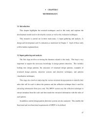
4.3.1 Use Case DiagramTo understand the system requirements, at first the researcher needs to identify theactors who will be using the system. From the high level business point <strong>of</strong> view, theusers would be those who are involving in colour supply chain <strong>of</strong> textile industry, suchas colour specifiers, middlemen, and mills (colour suppliers).However, as described in the previous chapter, the researcher is planning to constructcolour communication Web services which could be reused and further extended by anythird party Web-based applications, and these Web applications will be communicatingwith the proposed Web services via SOAP messages, therefore the actors in the context<strong>of</strong> the proposed system would be any third party Web-based applications that areinvolving in the colour communication process <strong>of</strong> the textile industry.Next, the researcher needs to identify the functional requirements with highcommonality across the colour supply chain so that most <strong>of</strong> the applications along thecolour communication process <strong>of</strong> textile industry can be made use <strong>of</strong> the proposed Webservices.The functional requirements in which reflect the common actions done by differentactors across the colour supply chain <strong>of</strong> textile industry would be depicted by the usecase diagram on the next page:62
4.3.2 Use Case ScenariosIn object-oriented programming, each use case diagram could be further translated intoa use case scenario in natural language that describes the detailed interaction betweenthe actor and the system. The scenario <strong>of</strong> each use case is a great way in examining whodoes what in the interaction among objects and what role they play (Bahrami, 1999).Each textual use case scenario is consisting <strong>of</strong> three portions. The header contains theinformation pertaining to use case’s topic, goal to be achieved by the use case,precondition and trigger for the actor to start a use case, success and failed endcondition <strong>of</strong> the use case and the primary actor that carries out the use case. Basic flow<strong>of</strong> events illustrates the normal flow <strong>of</strong> steps that will be gone through by the actor inorder to complete a use case while alternative flows and exceptions state the systemresponse whenever exceptional interaction between the system and the actor is occurred.Figure 4.2 to Figure 4.7 present the detailed textual description for each use casederived from Figure 4.1.64
Use CaseGoal in ContextPreconditionSuccess End ConditionFailed End ConditionPrimary ActorTriggerInitiate user session.User successfully logged on into the system.The user has an account existed in the database.User successfully logged on into the system.User failed to log on into the system.User <strong>of</strong> Web-based Colour Communication System.The actor executes “log in” function.Basic Flow <strong>of</strong> EventsActor Action1. User selects “Log in” function.3. User enters username and passwordSystem Response2. System displays “Log in” module.4. System authenticates user’s credentialand log him into the system by creating auser session for him.Figure 4.2: Textual description for use case scenario “Initiate user session”Use CaseGoal in ContextPreconditionSuccess End ConditionFailed End ConditionPrimary ActorTriggerTerminate user session.User successfully ended his session and logged out fromthe system.The user has an account existed in the database and haslogged on into the system with a action user session.User successfully logged out from the system.User failed to log out from the system.User <strong>of</strong> Web-based Colour Communication System.The actor executes “Log out” function.Basic Flow <strong>of</strong> EventsActor Action1. User selects “Log out” function.System Response2. System ends user’s current session andlogs him out from the system.Figure 4.3: Textual description for use case scenario “Terminate user session”65
Use CaseGoal in ContextPreconditionSuccess End ConditionFailed End ConditionPrimary ActorTriggerSearch Colour from central repository.The target colour(s) can be found via search function.The target object(s) exist in the central repository <strong>of</strong> theuser account.The target colour(s) is/are found.The target colour(s) is/are not found.User <strong>of</strong> Web-based Colour Communication System.The actor excecutes “search colour” function.Basic Flow <strong>of</strong> EventsActor Action1. User selects “search colour” function.3. User either keys in the searchkeywords <strong>of</strong> the colour name or enters thereflectance values <strong>of</strong> the target colour andacceptable colour difference.System Response2. System displays “Search Colour”module.4. System searches for the target color(s)from the central repository and returns thecolour(s) found in search result page.Alternative flows andexceptionsa) At step 4, the target colour doesn't exist in therepositoryThe system returns nothing on the search resultpage.Figure 4.4: Textual description for use case scenario “Search Colour from centralrepository”66
Use CaseGoal in ContextPreconditionSuccess End ConditionFailed End ConditionPrimary ActorTriggerCompare colours.The comparison result between target colour and matchcolours under different combination <strong>of</strong> illuminants andobservers are shown in different colourspace valuestogether with on-screen colour tiles.There are more than one colours chosen by the user forthe comparison purpose.The comparison result between target colour and matchcolours under different combination <strong>of</strong> illuminants andobservers are shown in different colourspace values.The comparison result between target colour and matchcolours under different combination <strong>of</strong> illuminants andobservers failed to be shown in different colourspacevalues.User <strong>of</strong> Web-based Colour Communication System.The actor executes “compare colours” function.Basic Flow <strong>of</strong> EventsActor Action1. User selects “compare colours”function.3. User selects the colours that he wishesto compare from the colour list.5. User selects the target colour as thereference point for the comparison.7. User selects the colours to be comparedwith the reference point colour.Alternative flows andexceptionsSystem Response2. System displays “compare colours”module.4. System retrieves the detailed informationregarding the selected colour objects.6. System displays the selected colour asthe reference point.8. System displays the selected colours onthe User Interface screen, colour spacevalues <strong>of</strong> all selected colours and the colourdifference between each selected colourwith the colour acts as reference point.a) At step 3, user doesn't find the digital colour object(s)which he wishes to choose.Use case end.Figure 4.5: Textual description for use case scenario “Compare colours”67
Use CaseGoal in ContextPreconditionSuccess End ConditionFailed End ConditionPrimary ActorTriggerImport digital colour reading files into central repositoryThe different format <strong>of</strong> colour reading files can beimported into central repository.The file to be imported is a valid file which could berecognized by the system.The selected colour reading files success to be importedinto central repository.The selected colour reading files failed to be importedinto central repository.User <strong>of</strong> Web-based Colour Communication System.The actor executes “import colour file” function.Basic Flow <strong>of</strong> EventsActor Action1. User selects “import colour file”function.3. User selects target directory incentral repository which will be used tostored imported digital colour readingfile.5. User browses and chooses the targetcolour reading file to be imported.7. User selects the colours from the file tobe imported into central repository.System Response2. System displays “import colour file”module.4. System displays the browser page tolocate the file to be imported in user'scomputer.6. System displays the colours containingin the selected file.8. System imports the colours selected fromthe digital colour reading file into the targetdirectory in the central repository specifiedby the user.Figure 4.6: Textual description for use case scenario “Import digital colour reading fileinto central repository”68
Alternative flows andexceptionsa) At step 7, the target colour reading file doesn't exist inuser's computer.Use case end.b) At step 8, the colour reading file contains no colour.System displays display 'No reflectance(s)found'message in Reflectances' column.Use case end.Figure 4.6, continuedUse CaseGoal in ContextPreconditionSuccess End ConditionFailed End ConditionPrimary ActorTriggerExport digital colour reading file from central repositoryThe digital colour objects stored in central repository canbe exported into different formats <strong>of</strong> different vendorapplications.The central repository contains digital colour objects.The selected digital colour object(s) success to beexported in the format specified by the user.The selected colour reflectance object(s) failed to beexported in the format specified by the user.User <strong>of</strong> Web-based Colour Communication System.The actor executes “export colour file” function.Basic Flow <strong>of</strong> EventsActor Action1. User selects “export colour file”function.3. User selects the colours that he wishesto export from the central repository.System Response2. System displays “export colour file”module.4. System displays the browser page foruser to locate the directory <strong>of</strong> the hard drivefor him to export the digital colour readingfile.Figure 4.7: Textual description for use case scenario “Export digital colour reading filefrom central repository”69
5. User browses and chooses the targetdirectory for him to export the digitalcolour reading file.6. System exports a colour reading fileaccording to the file format specified by theuser into the target directory.Alternative flows andexceptionsa) At step 3, user doesn't find the digital colour object(s)which he wishes to choose.Use case end.b) At step 5, user doesn't find the file format which hewishes to choose.Use case end.Figure 4.7, continued70
4.4 Use Case RealizationThe activity involved in the process from requirement modelling to implementation foreach use case is known as use case realization (Bennett et al, 2002).Use case realization involves the identification <strong>of</strong> possible set <strong>of</strong> classes and theinteraction between those classes in delivering functionality <strong>of</strong> the use case (Bennett etal, 2002).From the use case descriptions getting from the previous section, use case realizationswill be presented in the form <strong>of</strong> collaboration diagrams and then class diagrams.71
4.4.1 Collaboration DiagramsSeveral collaboration diagrams had been produced by the researcher during the stage <strong>of</strong>use case realization. These collaboration diagrams represent intermediate forms thatrealize their associated use cases.In the process <strong>of</strong> use case realization, the researcher was moving one step closer inconceiving the design model by identifying preliminary boundary class, entity class,control class and the interaction between all these classes within the given boundary <strong>of</strong>each collaboration diagram. Although the classes and interactions identified by theresearcher at this stage might be removed, replaced or further refined when thedevelopment process goes on, this information serves as a useful input in understandingthe behavioural aspects <strong>of</strong> the system requirements.Please note that in the collaboration diagrams shown in this section, each interactionbetween the use case actor and a class as well as the interaction between differentclasses is marked with a sequence number. This is to indicate the sequence <strong>of</strong> eachinteraction step to be executed under each collaboration scenario.The following subsections present the collaboration diagrams which were furtherdeveloped based on the input gathered from their corresponding use cases that had beendiscussed earlier in section 4.3.1 and section 4.3.2.72
4.4.1.1 Initiate User Session Collaboration DiagramFigure 4.8: Initiate user session collaboration diagramFigure 4.8 shows that the “Initiate User Session” use case has been evolved into acollaboration diagram. Use case actor and the other three classes, namely LoginUI class,AuthenticateAccount class and UserAccount class are collaborating among each otherin order to realize the “Initiate User Session” use case.<strong>Table</strong> 4.1 presents the role or class type held by each class in this collaboration diagram.<strong>Table</strong> 4.1: Classes in search colours collaboration diagramClass NameClass Type / RoleLoginUIBoundary ClassAuthenticateAccount Control ClassUserAccountEntity Class73
4.4.1.2 End User Session Collaboration DiagramFigure 4.9: End user session collaboration diagramFigure 4.9 shows that the “End User Session” use case has been evolved into acollaboration diagram. Use case actor and the other three classes, namely LogoutUIclass, TerminateSession class and UserAccount class are collaborating among eachother in order to realize the “End User Session” use case.<strong>Table</strong> 4.2 presents the role or class type held by each class in this collaboration diagram.<strong>Table</strong> 4.2: End user session collaboration diagramClass NameClass Type / RoleLogoutUIBoundary ClassTerminateSession Control ClassUserAccountEntity Class74
4.4.1.3 Search Colours Collaboration DiagramFigure 4.10: Search colours collaboration diagramFigure 4.10 shows that the “Search colours” use case has been evolved into acollaboration diagram. Use case actor and the other three classes, namelySearchColourUI class, SearchColour class and ColourObject class are collaboratingamong each other in order to realize the functional requirements captured in “Searchcolours” use case.<strong>Table</strong> 4.3 presents the role or class type held by each class in this collaboration diagram.<strong>Table</strong> 4.3: Classes in search colours collaboration diagramClass NameClass Type / RoleSearchColourUIBoundary ClassSearchColourControl ClassColourObjectEntity Class75
4.4.1.4 Compare Colours Collaboration DiagramFigure 4.11: Compare colours collaboration diagramFigure 4.11 shows that the “Compare Colours” use case has been evolved into acollaboration diagram. Use case actor and the other four classes, namelyCompareColourUI class, CompareColour class, CalculateColourDifference class andColourObject class are interacting between each other in order to realize the functionalgoals represented by “Search colours” use case.<strong>Table</strong> 4.4 presents the role or class type held by each class in this collaboration diagram.<strong>Table</strong> 4.4: Classes in compare colours collaboration diagramClass NameClass Type / RoleCompareColourUI Boundary ClassCompareColourControl ClassCalculateColourDifference Control ClassColourObjectEntity Class76
4.4.1.5 Import Colours Collaboration DiagramFigure 4.12: Import colours collaboration diagramFigure 4.12 shows that the “Import Colours” use case has been evolved into acollaboration diagram. Use case actor and the other three classes, namelyImportColourUI class, ImportColour class, and ColourObject class associate with eachother via different class methods in order to realize the functional requirementsspecified in “Search colours” use case.<strong>Table</strong> 4.5 presents the role or class type held by each class in this collaboration diagram.<strong>Table</strong> 4.5: Classes in import colours collaboration diagramClass NameClass Type / RoleImportColourUIBoundary ClassImportColourControl ClassColourObjectEntity Class77
4.4.1.6 Export Colours Collaboration DiagramFigure 4.13: Export colours collaboration diagramFigure 4.13 shows that the “Export Colours” use case which has been evolved into acollaboration diagram. Use case actor and the other three classes, namelyExportColourUI class, ExportColour class, and ColourObject class are collaboratingwith each other step by step in order to realize the functional requirements stated in“Search colours” use case.<strong>Table</strong> 4.6 presents the role or class type held by each class in this collaboration diagram.<strong>Table</strong> 4.6: Classes in export colours collaboration diagramClass NameClass Type / RoleExportColourUIBoundary ClassExportColourControl ClassColourObjectEntity Class78
4.4.2 Class Diagram4.4.2.1 Class Diagrams for Initiate and Terminate User SessionThe classes involved in both “Initiate User Session” use case and “End User Session”use case are pretty simple and straightforward as shown in Figure 4.14 below. LoginUIclass and LogoutUL class are playing the role as boundary classes to receive the log onrequest and log out instruction from a authorized Web service user. ManageUserSessionclass responsible to manage the processing logic to initiate or end a user session whileall the information such as user account id and password will always be authenticatedby UserAccount class.LoginUIManageUserSessionUserIDPasswordLogin(id, password)AuthenticateAccount()InitiatiateSession()TerminateSession()GetTimeStamp()SetTimeStamp Datetime ()LogoutUIUserAccountLogout()AccountIDCreationDateDeletedDateFullNameLastModifiedDatePasswordLastLoginTimeLastLogoutTimeGetTimeStamp()SetTimeStamp(Datetime)Figure 4.14: Class diagrams for initiate and terminate user session79
4.4.2.2 Class Diagrams Associate to the Representation <strong>of</strong> ColourWalker (1996) revealed that most computer applications specify colour in threecomponentsystems which are RGB (Red, Green and Blue), HLS (Hue, Lightness andSaturation), or HSV (Hue, Saturation and Value). Derived from the mechanisms <strong>of</strong>human colour perception, these colour spaces map relatively straightforwardly onto thedisplay and printing technologies.However, he pointed out that although human colour perception is well modelled by thethree-component systems mentioned above, the physical interaction <strong>of</strong> light and matteris far more complicated. A task as simple as rendering a scene under a variety <strong>of</strong> lightsources: daylight, incandescent and fluorescent indoor lighting, and mercury andsodium vapour street lights cannot be accomplished without knowing the spectra <strong>of</strong>light sources and the spectral response <strong>of</strong> pigments.Once the spectrum <strong>of</strong> the light impinging upon a point in the image plane is known, theeye's perception <strong>of</strong> that spectrum must be determined. Finally, display arguments mustbe calculated which evoke that perception in the viewer.From the observations mentioned above, in order to model the colour representationwhich closes to real world phenomena, the colour should allowed to be examined,compared and presented under different circumstances in which at most <strong>of</strong> time,determined by the presence <strong>of</strong> a particular combination <strong>of</strong> illuminant and observer.In this project, as the presence <strong>of</strong> fast changing illuminant and observer greatly affectthe visual appearance <strong>of</strong> an object (in the form <strong>of</strong> reflectance <strong>of</strong> spectrum wavelength),the researcher assumed that persisted colour does not exist in the system going to bedeveloped.80
Each colour is considered as an object, which stores one set <strong>of</strong> fixed data regarding thereflectance data <strong>of</strong> the colour. One set <strong>of</strong> reflectance data generates one colour under aparticular illuminant and observer.The class diagrams associate to the representation <strong>of</strong> colour are shown as Figure 4.15below:-ReflectanceCondition_APERTURECondition_LIGHTFILTERCondition_SPECULARCondition_MODECondition_AMBIENTTEMPERATURECondition_AMBIENTHUMIDITYCondition_LENSPOSITIONCondition_LAMPUSEDCondition_FLASHESCondition_MEASUREMENTSCondition_AVERAGEALGORITHMType_MEASUREType_NEWLY_RECEIVEDSpectroType_RECIPEType_PROFILEDSpectrumMap: SortedMapSpectrumConditionsSpectrumStartWaveLengthIntervalValuesSpectrum(start, interval, values)Create (start, interval, values)getLongestWavelength()getShortestWaveLength()getInterval()getValues()Reflectance()Relfectance(spectrum, conditions)getSpectrum()setSpectrum(spectrum: Spectrum)getSpectrumMap()setSpectrumMap(SortedMap)getConditions() : MapsetConditions(condition)getSpectro()setSpectro(Spectro)getType()setType(Type)Figure 4.15: Class diagrams associate to the representation <strong>of</strong> colour81
4.4.2.3 Class Diagrams for Search ColoursIn section 4.4.1.3, the researcher has identified three classes, which are SearchColourUIclass, SearchColour class and ColourObject class from the point <strong>of</strong> view <strong>of</strong>collaboration between classes.After considering the factor <strong>of</strong> colour physicsmathematics, these three classes are being refined and replaced with a set <strong>of</strong> new classesas shown in figure 4.16 in order to better reflect the nature <strong>of</strong> colourimetric calculation.SearchColourUIReplaced bySearchColourSearchColourReplaced byColourSearchIndexColourObjectReplaced byReflectanceSpectrumFigure 4.16 :Evolution <strong>of</strong> class diagrams for search colours use caseFigure 4.17 on the next page presents the association between classes involved in“Search Colours” use case. ColourSearchIndex class represents a point and radius thatdefines a sphere in a particular colour space. The set <strong>of</strong> points enclosed by this spherewill contain all the CIELab values for a particular reflectance under differentcombination <strong>of</strong> illuminants and observers.When a colour search query is made with a given CIELab value and delta E value, theset <strong>of</strong> points defined by the query will be compared to this set <strong>of</strong> points and if they areintersecting or overlapping, there is a possibility that this reflectance will meet thesearch criteria.82
SearchColoursobserverilluminantL_valuea_valueb_valuedE_valuereflectanceSearchColours()getObserver()setObserver()getIlluminant()setIlluminant()getA_value()setA_value()getB_value()setB_value()getB_value()setB_value()getDelta_E()setDelta_E()get_Reflectance()ColourSearchIndexreflectanceL_valuea_valueb_valueradius_valueColourSearchIndex()getL()geta()getb()getRadius()getReflectance()setL()seta()setb()setRadius()setReflectance()IlluminantsIlluminantsACCWFD50D55D65D75DaylightDeluxeF2F7F12TL83TL84U30SpectrumStartWaveLengthIntervalValuesSpectrum(start, interval, values)Create (start, interval, values)getLongestWavelength()getShortestWaveLength()getInterval()getValues()ReflectanceCondition_APERTURECondition_LIGHTFILTERCondition_SPECULARCondition_MODECondition_AMBIENTTEMPERATURECondition_AMBIENTHUMIDITYCondition_LENSPOSITIONCondition_LAMPUSEDCondition_FLASHESCondition_MEASUREMENTSCondition_AVERAGEALGORITHMType_MEASUREType_NEWLY_RECEIVEDSpectroType_RECIPEType_PROFILEDSpectrumMap: SortedMapSpectrumConditionsFigure 4.17: Class Diagrams for Search Colour83
4.4.2.4 Class Diagrams for Compare ColoursIn colour physics, assessments <strong>of</strong> colours difference between two objects are usuallydone by assessment on the colour difference (delta) from a known standard.CIELAB and CIELCH are the most widely used standards that used for calculatingcolour difference between two objects.For standard CIELAB, the expressions for these colour differences are ∆L* ∆a* ∆b* orDL* Da* Db*; while for CIELCH the expressions for colour differences are and ∆L*∆C* ∆H* or DL* DC* DH*.Figure 4.18 on the next page presents the association between classes involved in“Compare Colours” use case. ColourDifference class is the class that used to define themost common colour difference used in colour physics which is Delta E and thecomponents used to calculate Delta E such as Delta a*, Delta b*, Delta c*, Delta h* andso on.The CompareColours class is the central place for doing colour difference calculation. Itcomputes the colour difference between the colours <strong>of</strong> two objects based on the givencondition <strong>of</strong> observer illuminant and colour encoding types.Again, you will find that the four classes identified during section 4.4.1.4, namelyCompareColourUI class, CompareColour class, CalculateColourDifference class andColourObject had been refined and replaced with other class names. This is inevitableas the associations between different classes under a particular use case need to berefined in order to facilitate the processing logic <strong>of</strong> colourimetric calculation.84
CompareColourscolourEncodingsIlluminantsCompareColours()getInstance : CompareColourscomputeWeights(Illuminant , Observer, Interval)computeWhitePoint(Illuminant, Observer)getAlgorithmNames()getAlgorithm(String)create (Class, Illuminant, Reflectance, Observer)convert(Class, XYZ, XYZ)getColourEncodingNames()getColourEncodingClass(String)ACCWFD50D55D65D75DaylightDeluxeF2F7F12TL83TL84U30ColourDifferenceDELTA_EDELTA_L_starDELTA_a_starDELTA_b_starDELTA_c_starDELTA_h_starDELTA_u_starDELTA_v_starDELTA_LDELTA_cDELTA_hColourDifference()getAlgorithm ()getAllDeltaNames()getValue(String)ColourEncodingCIELabCIELchCIELuvCYMKXYZRGBFigure 4.18: Class Diagrams for Compare Colours85
4.4.2.5 Class Diagrams for Import Colours FunctionFigure 4.19 on the next page presents the association between classes involved in“Import Colours” use case. The purposes <strong>of</strong> defining an interface class,InterfaceImportColour which is implemented by another abstract classAbstractImportColour is due to the consideration that import colours function could beenhanced in the future in order to cater for more file formats. Interface class onlyconsists <strong>of</strong> methods with no code body (implementation <strong>of</strong> the method) while abstractclass is class which will not be instantiated, instead, its attributes and methods will beinherited or overridden by subclasses with concrete implementation logic. Theprogramming logic <strong>of</strong> importing and processing spectral data and attributes obtainedfrom the qtx file are all residing inside the ImportQTX class which plays the role ascontrol class. The colourimetric data represented by each colour contained in the qtx filewill be stored as Reflectance object.86
InterfaceImportColourgetName ()getDefaultExtension()doImport (file, template)doImport (stream, template)AbstractImportColourm_Namem_ExtensionAbstractImportColour (name, extension)getName()getDefaultExtension()doImport (filename, template)ReflectanceCondition_APERTURECondition_LIGHTFILTERCondition_SPECULARCondition_MODECondition_AMBIENTTEMPERATURECondition_AMBIENTHUMIDITYCondition_LENSPOSITIONCondition_LAMPUSEDCondition_FLASHESCondition_MEASUREMENTSCondition_AVERAGEALGORITHMType_MEASUREType_NEWLY_RECEIVEDType_RECIPEType_PROFILEDgetSpectrum()setSpectrum()getSpectrumMap()setSpectrumMap()getConditions()setConditions()getSpectro()setSpectro()getType()setType()TranslatorNameImportQTXImportQTX()doImport (stream , template)doImport( filename, template)parseHeader(line)parseData (reader, type, template, cachedKeys)putMap(str, map)revertToDefault(map)Figure 4.19: Class diagrams <strong>of</strong> import colours function87
4.4.2.6 Class Diagrams for Export Colours FunctionFigure 4.20 presents the association between classes involved in “Export Colours” usecase. The implementation logic <strong>of</strong> process and exporting the reflectance objects intodifferent set <strong>of</strong> spectral data into plain text content in a qtx file are all residing inside theExportQTX class. InterfaceExportColour class holds the role as interface class whileentity class, Reflectance represent the actual object that stores the colourimetric data <strong>of</strong>each colour visible to end user.InterfaceExportColourPROB_ILLUMINANTPROB_OBSERVERPROB_ICCPRINTERPROB_ICCMONITORgetName()getDefaultExtension()doExport(colours, out)doExport(reflectance, out)supportAttributes()requiresPrimary()supportMultipleColours()setProperties(properties)getProperties()AbstractExportColourNameExtensionPropsAbstractExportColour (name, extension)getName()getDefaultExtension()doExport(colours, out )doExport(reflectance , out )exportReflectance(reflectance, out)supportAttributes()resetState()setProperties(properties)getProperties()Reflectance- Condition_APERTURE : String- Condition_LIGHTFILTER : String- Condition_SPECULAR : String- Condition_MODE : String- Condition_AMBIENTTEMPERATURE : String- Condition_AMBIENTHUMIDITY : String- Condition_LENSPOSITION : String- Condition_LAMPUSED : String- Condition_FLASHES : String- Condition_MEASUREMENTS : String- Condition_AVERAGEALGORITHM : String- Type_MEASURE : STRING- Type_NEWLY_RECEIVED : String- Type_RECIPE : String- Type_PROFILED : String+ getSpectrum() : Spectrum+ setSpectrum(Spectrum) : void+ getSpectrumMap() : SortedMap+ setSpectrumMap(SortedMap) : void+ getConditions() : Map+ setConditions(Map) : void+ getSpectro() : Spectro+ setSpectro(Spectro) : void+ getType() : String+ setType(String) : voidExportQTXExportQTX ()requiresPrimary()supportMultipleColours()doExport ( colours , out )doExport ( colour , out, sequence)exportReflectance (reflectances , out )resetState()supportsAttributes()Figure 4.20: Class diagrams <strong>of</strong> export colours function88
4.5 SummaryUse case driven object-oriented approach has been applied during the process <strong>of</strong>eliciting, capturing, analysing and modelling the system requirements. In the early stage<strong>of</strong> system analysis, use cases are used to build an initial model based on users'requirements for a new system. Since the use cases are rather high level and concentrateon a user-centred view <strong>of</strong> the system, those use cases were being translated into analysisclass diagrams via use case realization steps which involved the usage <strong>of</strong> collaborationdiagrams. The outcome <strong>of</strong> use case realization, namely analysis class diagrams will beserving as the primary models for describing the internal structure and behaviour <strong>of</strong> theproposed colour communication Web services.89