Pro⢠- 645 - Douglas Sports Nets and Equipment
Pro⢠- 645 - Douglas Sports Nets and Equipment
Pro⢠- 645 - Douglas Sports Nets and Equipment

Create successful ePaper yourself
Turn your PDF publications into a flip-book with our unique Google optimized e-Paper software.
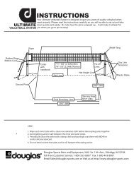
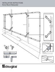
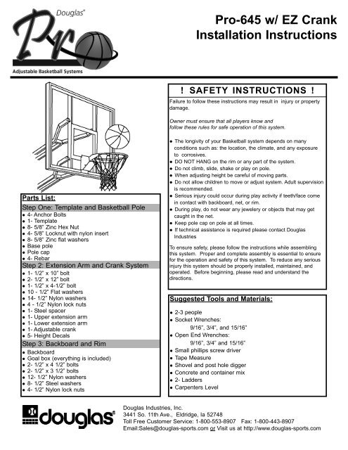
Pro-<strong>645</strong> w/ EZ CrankInstallation Instructions! SAFETY INSTRUCTIONS !Failure to follow these instructions may result in injury or propertydamage.Owner must ensure that all players know <strong>and</strong>follow these rules for safe operation of this system.Parts List:Step One: Template <strong>and</strong> Basketball Pole 4- Anchor Bolts 1- Template 8- 5/8” Zinc Hex Nut 4- 5/8” Locknut with nylon insert 8- 5/8” Zinc flat washers Base pole Pole cap 4- RebarStep 2: Extension Arm <strong>and</strong> Crank System 1- 1/2” x 10” bolt 2- 1/2” x 12” bolt 1- 1/2” x 4-1/2” bolt 10 - 1/2” Flat washers 14- 1/2” Nylon washers 4 - 1/2” Nylon lock nuts 1- Steel spacer 1- Upper extension arm 1- Lower extension arm 1- Adjustable crank 5- Height DecalsStep 3: Backboard <strong>and</strong> Rim Backboard Goal box (everything is included) 2- 1/2” x 4 1/2” bolts 2- 1/2” x 3 1/2” bolts 12- 1/2” Nylon washers 8- 1/2” Steel washers 4- 1/2” Nylon lock nuts The longivity of your Basketball system depends on manyconditions such as: the location, the climate, <strong>and</strong> any exposureto corrosives. DO NOT HANG on the rim or any part of the system. Do not climb, slide, shake or play on pole. When adjusting height be careful of moving parts. Do not allow children to move or adjust system. Adult supervisionis recommended. Serious injury could occur during play activity if teeth/face comein contact with backboard, net, or rim. During play, do not wear any jewelery or objects that may getcaught in the net. Keep pole cap on pole at all times. If technical assistance is required please contact <strong>Douglas</strong>IndustriesTo ensure safety, please follow the instructions while assemblingthis system. Proper <strong>and</strong> complete assembly is essential to ensurefor the operation <strong>and</strong> safety of this system. To reduce any seriousinjury this system should be properly installed, maintained, <strong>and</strong>operated. Before beginning, please read <strong>and</strong> underst<strong>and</strong> thedirections.Suggested Tools <strong>and</strong> Materials: 2-3 people Socket Wrenches:9/16”, 3/4”, <strong>and</strong> 15/16” Open End Wrenches:9/16”, 3/4” <strong>and</strong> 15/16” Small phillips screw driver Tape Measure Shovel <strong>and</strong> post hole digger Concrete <strong>and</strong> container mix 2- Ladders Carpenters Level<strong>Douglas</strong> Industries, Inc.3441 So. 11th Ave., Eldridge, Ia 52748Toll Free Customer Service: 1-800-553-8907 Fax: 1-800-443-8907Email:Sales@douglas-sports.com or Visit us at http://www.douglas-sports.com
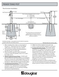
Step 1: Template <strong>and</strong> Basketball PoleA. Ensure ground is levelwith playing surface.Dig hole 16" wide <strong>and</strong>48" deep.Figure 1: Concrete Footing48"16"Playing SurfaceGround Surface18"B. Assemble mounting plate. Attach 4, 5/8" nuts 2 1/4" fromtop of anchor bolts. Set template on bolts. Place 4 more5/8" nuts on top of template. Position anchor bolts asillustrated in Figure 2.C. Pour concrete into the hole 18" from the top. Place fourrebars 8" apart forming a square in the center of hole asillustrated in Figure 1.D. Finish pouring concrete into hole. Release air pockets inconcrete.E. Drop anchor bolts into the center of the wet concrete untiltemplate is flush with cement. Level mounting plate <strong>and</strong> makesure it's parallel with playing surface. Add 4, 5/8" flat washers ontop of nuts. Clean off any excess cement on mounting plate atthis time.NOTE: Check leveling of mounting plate several times whileconcrete is curing. Front of mounting plate must be parallelwith playing surfaceIMPORTANT! Do Not proceed to Step F until concrete has cured.A minimum of 72 hours. Allow additional time for cold, wet, orhumid weather.WARNING! Two person minumum required for Step F .Not following this warning may resullt in an injury<strong>and</strong>/or property damage.Figure 3: CapPlacementpost capF. Remove basketball pole from box <strong>and</strong> place postcap on the TOP of the pole.G. Place basketball pole onto the bolts, add4 5/8" flatwashers on top of base plate, thenthe 4 nylon lock nuts.H. Use level to check for proper verticalalignment, then tighten nylon lock nuts.NOTE: Nuts at the top of assembly are usedfor leveling the system after fully assembled.Figure 2: Anchor Plate Assembly5/8" flat washersanchortemplatePlaying Surface(Concrete Pad)1-3”Figure 4: Pole Placement5/8" nuts2-1/4" from topanchor boltsAnchor System Option:As an installation option, you can install theanchor system up to 3” lower than yourplaying surface. This allows an area to hidethe anchor bolts with rock, gravel or mulch.8"nylon lock nut5/8" flat washerRebarPro-<strong>645</strong>EZ2
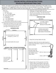
Step 2: Extension Arms <strong>and</strong> Crank SystemFigure 5: Extension Arms1/2" lock nut1/2" flat washer1/2" nylon1/2" nylonsupperextensionarmlowerextensionarm10" bolt,1/2" flat washer,1/2" nylonA. Locate lower extension arm.B. With 2 people, insert 9" bolt, 1/2" flatwasher,<strong>and</strong> 1/2" nylon through back of extension arm<strong>and</strong> into lower welded spacer. In betweenboth arms <strong>and</strong> the pole (on both sides ofpole), place a 1/2" nylon. On the other side ofextension arm, finish off with a 1/2" nylon, 1/2"flat washer, <strong>and</strong> a 1/2" lock nut.C. Locate top extension arm.D. Repeat Step B(See Figure 5 for illustration)12" bolt,1/2" flat washer,1/2" nylonE. Locate opening at the top of adjustable crank.F. Line up crank with open holes at the back oflower extension arm. Insert 9" bolt, flat washers<strong>and</strong> nylon washers as shown <strong>and</strong> tighten.G. Line up steel spacer at bottom of crank <strong>and</strong>Insert 4-1/2” bolt, flat washers <strong>and</strong> nylonwashers as shown <strong>and</strong> tighten into crank.Figure 6: Adjustable EZ Crank1/2" lock nut1/2" flat washer1/2" nylon1/2" nylon12" bolt,1/2" flat washer,1/2" nylonFigure 7:Completed Step 2protctive sleeve1/2" lock nut1/2" flat washer1/2" nylonFigure 8:Post Lockoptionalpost lock( lock is notincluded)steel spaceradjustablecrank4-1/2" bolt1/2" flat washer1/2" nylonPro-<strong>645</strong>EZ3
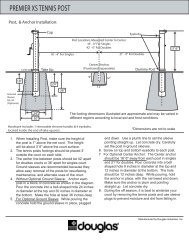
Step 3: Backboard <strong>and</strong> RimA. Lower system to the safety stop.B. With three people, two people hold upthe backboard <strong>and</strong> the third personinserts: 4, 3-1/2" bolts12, 1/2" nylon washers8, 1/2" steel flatwashers4, 1/2" lock nutsFigure 9: Backboard <strong>and</strong> RimbackboardrimC. Locate rim pad, peel offadhesive <strong>and</strong> place onbackboard at rim locationD. Assemble rim with enclosedhardwareE. Fasten rim cover under rimF. Hang NetG. Check leveling of pole. Poleshould be level in alldirections.Note: If adjustment isnecessary, adjust system byrotating the nuts. After systemis level, completely tighten nuts.1/2" nylon1/2" steel washer1/2" lock nut1/2" nylonFigure 10:Height Adjustment3-1/2" bolt1/2" steel washer1/2" nylonNOTE: All hardware for goalis included in rim package.3-1/2" bolt1/2" steel washer1/2" nylonStep 4: Height Adjustment DecalA. Raise system to 6’ from rim. (Measuringfrom top of rim to the ground.)B. With a marker, draw a line right above the sleeveon the inside metal part of the crank system.(See Figure 10) Note: Placing the decals on the frontor sides of the crank may cause them to peel off.C. Raise system to 7' from rim.D. Make another mark at edge of sleeve.E. Continue marking lines at 8’, 9’ <strong>and</strong> 10’F. Place provided numerical decals on the galvanizedsteel to align with the designated heightmeasurement marks. Note: For accuracy, the blackline on the decal under the numbers should matchup with the determined marker height.G. Height should now be set. Adjust if needed.Note: Regulation rim height is 10 feet.heightlabelsblackprotectivesleeveTurn h<strong>and</strong>leclockwiseto lower6’10’9’8’7’markhereTurn h<strong>and</strong>lecounterclockwiseto raisePro-<strong>645</strong>EZ4