Purolite SST-60 High Efficiency Cation Exchange Resin
Purolite SST-60 High Efficiency Cation Exchange Resin
Purolite SST-60 High Efficiency Cation Exchange Resin

You also want an ePaper? Increase the reach of your titles
YUMPU automatically turns print PDFs into web optimized ePapers that Google loves.
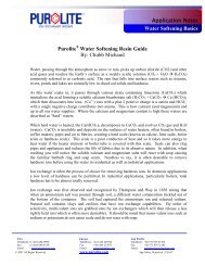
Under a microscope, PUROLITE <strong>SST</strong> resins lookdifferent than other resins. That’s because the resinshave inert centers. Only the outer shell is functionalized.(See Figure 1)By shortening the diffusion path (See Figure 2)through the use of shallow shell technology, eachresin bead presents the same depth of functionalitywhich leads to more efficient use of regenerant andtherefore, better regeneration. This in turn leads tohigher capacities, lower leakages and better handlingof iron.PUROLITE <strong>SST</strong> resins exhibit superior toughness anddurability of osmotic shock versus conventional resins.This is key in industrial applications and portableexchange units where the resin sees a lot of physical handling.These resins save water too. The shallow shelltechnology of PUROLITE <strong>SST</strong> products regeneratewith about 50% less water and rinse very quickly toquality.<strong>SST</strong>Uniform Depthof Functionalitysr<strong>SST</strong>Standard. . . every bead reacts at the same rateFig. 1 Uniform Depth of FunctionalityShell Radius .5 .6 .7 .8 .9 1.0Volume Ratio 87.5% 93.6% 97.3% 98.7% 99.9% 100%Fig. 2 Diffusion Path<strong>SST</strong>-<strong>60</strong> ADVANTAGES• <strong>High</strong>er Recovered Capacity Per Pound of Salt• Lower Leakages at All Regenerant Levels• Better Iron Removal• Lower Rinse Requirements• No equipment Modifications Needed• Less Susceptible to Iron Fouling• Shorter Regeneration Cycles• Superior Physical Strength• More Resistant to Oxidation• Non-Solvent SulfonatedPage 2 of 8
Standard Operating Conditions(Co-current Softening of Water)Operation Rate Solution Minutes AmountService 8 - <strong>60</strong> BV/h Influent water per design per design1.0 - 7.5 gpm/ft 3Backwash Refer to Fig. 4 Influent water 5 - 20 1.5 - 4 BV5º - 30ºC 10 - 20 gal/ft 3(40º - 80ºF)Regeneration 2 - 7 BV/h 8 - 20% NaCl 10 32 - 340 g/l0.25 - 0.9 gpm/ft 3 2 - 15 lb/ft 3Rinse, (slow) 2 - 7 BV/h Influent water 12 - <strong>60</strong> 1.5 - 2 BV0.25 - 0.90 gpm/ft 3 10 - 15 gal/ft 3Rinse, (fast) 8 - 40 BV/h Influent water 6 - 30 1 - 5 BV1.0 - 5.0 gpm/ft 3 8 - 40 gal/ft 3Backwash Expansion 50% to 75%Design Rising Space 100%"Gallons" refer to U.S. Gallon = 3.785 litersFig. 3 PRESSURE DROP VS FLOW RATEFig. 4 BACKWASH EXPANSIONFLOW RATE, U.S. gpm/ft 2BACKWASH FLOW RATE, U.S. gpm/ft 2PRESSURE DROP, kg/cm 2 /m of bed depth1.21.00.80.<strong>60</strong>.40.200 8 16 24 32 405°C (41°F)10°C (50°F)20°C (68°F)25°C (77°F)0 20 40 <strong>60</strong> 80 10054321PRESSURE DROP, psi/ft of bed depthBED EXPANSION, Percent12010080<strong>60</strong>402000 4 8 12 16 205°C (41°F)10°C (50°F)20°C (68°F)25°C (77°F)0 10 20 30 40 50FLOW RATE m/hFLOW RATE m/hPage 3 of 8
PUROLITE <strong>SST</strong>-<strong>60</strong> vs C-100CAPACITYFig. 5 OPERATING CAPACITYKgr/CF33OPERATING CAPACITY Kgr/CF28231813<strong>SST</strong>-<strong>60</strong>C-10080 2 4 6 8 10 12 14 16REGENERATION LEVEL # NaCl/CF<strong>SST</strong>-<strong>60</strong> C-100NaClOp. Cap Op. Cap(#/CF)(Kgr/CF) (Kgr/CF)2 11.2 9.23 14.8 12.84 18.0 15.25 20.0 18.26 22.5 19.57 24.5 22.38 25.0 24.39 26.2 25.610 27.4 26.912 30.0 28.515 31.1 29.4Page 4 of 8