Multi-Power ® Cylinders - Fabco-Air, Inc.
Multi-Power ® Cylinders - Fabco-Air, Inc.
Multi-Power ® Cylinders - Fabco-Air, Inc.

Create successful ePaper yourself
Turn your PDF publications into a flip-book with our unique Google optimized e-Paper software.
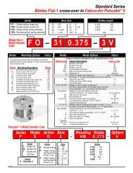
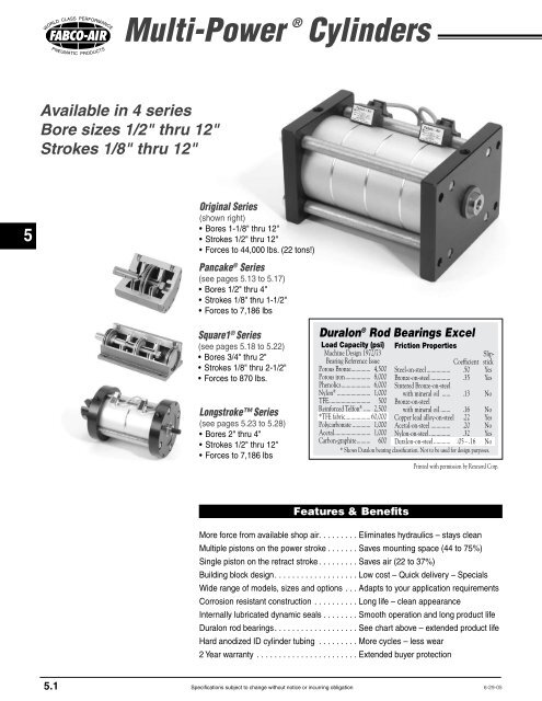
<strong>Multi</strong>-<strong>Power</strong> ® <strong>Cylinders</strong>Basic Construction5<strong>Multi</strong>ple Stage Extendwith Single Stage RetractSingle RetractReturn Stroke<strong>Multi</strong>ple Extend<strong>Power</strong> StrokeNPT Port 1 12 2 3 4 5NPT Port213161772019 1815 14 13 15<strong>Multi</strong>ple Stage Retractwith Single Stage Extend<strong>Multi</strong>ple Retract<strong>Power</strong> StrokeNPT Port 1 12 2 3 4213161772019 18515 14 13 1511Single ExtendReturn Stroke11678910NPT Port678910Quick Reference to ComponentsNo. Description1 Cylinder tube seal2 Atmospheric vent3 Piston rod4 <strong>Air</strong> passage between stages5 Center stud, high tensile, plated6 Stainless steel tie rods and plated steel nuts7 Piston stop8 Cap End Plug, aluminum, black anodized9 Nut, plated steel10 Piston Rod Pilot Washer locates pistonto maintain precise concentricity11 Cap end head, aluminum, black anodized12 Cylinder tube, aluminum13 Baffle, aluminum14 Baffle seal, Buna-N O'Rings, –25° to + 250°F15 Piston seal, internally lubricated O'Ring16 Piston rod seal, internally lubricated O'Ring17 Center shaft seal, internally lubricated O'Ring18 Piston, aluminum19 Piston air slot, note direction of air flow20 Rod end head, aluminum, black anodized21 Piston rod bushing, anodized aluminumhousing with Teflon ® lined Duralon ® insertCylinder OD – is clear anodized aluminum for corrosionresistance and an attractive appearance.The Bore ID is Hard Anodized – Hard anodizing isan electrochemical process which provides a very densesurface of aluminum oxide that actually impregnates thebase aluminum. It forms an extremely hard (60 Rc) surfacewith a low coefficient of friction. Hardness, corrosionresistance and wear resistance exceeds that of chromeplated steel.An Extra Long Rod Bearing – provides long and rigidsupport for the piston rod. The bearing material is Duralon ®on all bore sizes. See page 5.1 for a chart comparing theexceptional physical properties of Duralon ® to other, lessdurable, bearing materials.The Piston Rod – is Hard Chrome Plated StainlessSteel. Surface finish is 12 RMS or better.The standardrod end is fine female thread tapped and has long wrenchflats.Piston Construction – The piston is aluminum for lightweight. The piston rod pilot end and a pilot washer enablebolting the assembly securely while maintaining preciseconcentricity for smooth cylinder performance.Dynamic Seals – Internally lubricated O'Rings arecompounded to provide extra long wear, lower breakaway(starting) and running friction, and smoother operation. Intests, cylinders with these seals have extended cycle life 2to 3 times beyond cylinders with standard Buna-N seals.5.3Specifications subject to change without notice or incurring obligation10-30-04
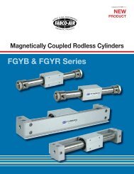
<strong>Multi</strong>-<strong>Power</strong> ® mp rf.eps <strong>Cylinders</strong>1-1/8", 1-5/8", 2-1/2", 3", 4", 5", & 6" Bores-FFC 4E SFront Face Mount; Rod End Rectangular Flange<strong>Fabco</strong> mounting patternQ1Kmp ff.epsJ M2TTNHex Nut4 PlacesCap End-RFC 4E SNHex Nut4 PlacesRod EndRear Face Mount; Cap End Rectangular Flange<strong>Fabco</strong> mounting patternUQKT T1AOThd3LSEBD2J MFRGHAR5AOThd3LSEBDFGRHARU-RFAmp rfa.epsRear Face Mount; Cap End Rectangular FlangeNFPA (MF2) mounting patternUGQ 1 KAOT TThd-FFAESAOThd4CCmp ffa.epsFront Face Mount; Rod End Rectangular FlangeNFPA (MF1) mounting patternQ13LSEBBDDKDimensions (inches)2J MFF‡ Note:The “Dimension Y” is for standard models: <strong>Multi</strong>ple extend/singleretract and Single extend/multiple retract. Optional <strong>Multi</strong>ple extend/multiple retract models require additional cylinder length (see page 5.7).The following options also require additional cylinder length. See therespective option information pages for details. -NR, –NRDR (pg 5.8),-HS (pg 5.11), -TF, -TR, -TFR (pg 5.10), -E (pg 5.12).† Note:“Dimension K” for 8" Bore only, specify Option –KF for 1"-14 Rod ThreadGTRRAUHFABCO 1-5/8" = NFPA 1-1/2"FABCO 3" = NFPA 3-1/4"TNHex Nut4 PlacesCap EndS4ECCNHex Nut4 PlacesRod End2J MFF3RRLAS HEBB FABCO 1-5/8" = NFPA 1-1/2"DD FABCO 3" = NFPA 3-1/4"mp mp1.epsFor single stage retract onlyClevis Mount (NFPA MP1 Dimensions)-PM - Ports in-line with slot-SM - Ports 90° to slotFLT TLRERJ MRRAGUH RFMaterial: Gray Iron Casting,Black Oxide FinishCD PinCross Pin andClips <strong>Inc</strong>luded<strong>Fabco</strong> 1-1/8" = NFPA 1-1/2"<strong>Fabco</strong> 1-5/8" = NFPA 1-1/2"<strong>Fabco</strong> 3" = NFPA 3-1/4"CBCW CWECL3-8-01N Hex Nut 4 PlacesBoth Ends 2-1/2" thru 6" Bores;Rod end only 1-1/8" & 1-5/8" BoresBore1-1/81-5/82-1/2345681012A= (No. stages x stroke) + y ‡y ‡ (2 stage)1.862.422.912.912.913.813.466.257.757.75y ‡ (3 stage)2.413.083.763.763.765.154.558.2510.7510.75y ‡ (4 stage)2.963.754.614.614.616.505.6510.2513.7513.75B2.002.503.633.885.006.007.007.579.4011.10C1.251.752.382.753.754.505.25NANANAD2.503.004.254.506.007.008.00NANANAE1.752.253.003.505.006.007.009.0012.0014.00F.28.28.34.34.41.53.53.69.78.78G.13.13.19.19.19.19.19.25.25.25H.50.50.50.50.50.69.691.001.001.00J±.0020.7521.0011.1271.1271.5021.7521.7522.0012.7512.751K †5/16-24x.633/8-24x.631/2-20x.751/2-20x.751/2-20x.753/4-16x1.133/4-16x1.131-12x1.50 †1 1 /2-12x1.751 1 /2-12x1.75L7/161/25/85/87/8111-1/41-3/41-3/4M±.0010.5000.6250.7500.7501.0001.2501.2501.5002.0002.000N7/167/169/169/163/43/43/43/41-1/81-1/8P2.382.883.694.135.506.253.38NANANAQNPT1/81/81/41/41/41/41/41/21/21/2R.50.63.75.75.75.75.751.501.501.505.5Specifications subject to change without notice or incurring obligation1-22-08
▼Mounting Styles with Dimensions8", 10", and 12" Bores1-1/8", 1-5/8", 2-1/2", 3", 4", 5", & 6" Bores-FFAmp 8ff.epsFront Face Mount; Rod End Square FlangeNFPA (ME3) mounting pattern-FTmp ft.epsFoot MountQRod End View 1KTTHTHCFS4EQ 13LSPFO2KGJ MXZRHTT.25Amp wfr.eps-WF Extended Tie Rod Mount, Rod End Only-WR Cap End Only-WFR Rod & Cap EndsHGQKT T1E 4J MS23LRRS V VE WFWRA ▼To OrderExtended Tie Rod MountSpecify SuffixRod End only –WFCap End only –WRRod & Cap Ends –WFRRZNHex Nut4 PlacesBothEndsXAOThdNHex Nut4 PlacesBothEndsALLModelsIf a non-standard extensionis required, specify by addingthe required length tothe suffix.e.g. If –WF length requiredis 2.5", Specify –WF2.5"-WF-WR-WFRQ44-RFAUK Ta pL FlatsJMNHex Nut8 PlacesRod EndHS3LWBEhp 8wrf.epsExtended Tie Rod Mount, Rod End OnlyCap End OnlyRod & Cap EndsWFWR1 KT T3W LSE22JJ MAOThdFHmp 8rf.epsRear Face Mount; Cap End Square FlangeNFPA (ME4) mounting patternRGMGHRRT T Q Cap End View1AR4GAA3WBSERR2NHex Nut8 PlacesCap EndVUAOThdFAOThdNHex Nut8 PlacesBothEnds5Bore1-1/81-5/82-1/2345681012S1.191.622.312.693.504.255.137.9010.6312.46T.22.25.31.31.31.31.31.75.75.75U.27.27.38.38.50.50.50.50.80.80V.22.22.33.33.43.43.43.43.66.66WNANANANANANANA4.565.005.81X.31.38.44.50.63.75.75NANANAZ.44.63.56.75.881.001.00NANANAAO1/4-201/4-203/8-163/8-161/2-131/2-131/2-131/2-133/4-103/4-10BB2.002.753.884.695.446.637.63NANANACC1.001.432.192.763.324.104.88NANANADD2.503.254.505.316.387.638.63NANANAFF.22.28.34.41.41.53.53NANANAFO3.003.504.384.886.387.257.00NANANAHC1.131.381.752.002.753.253.75NANANAHT2.002.503.253.755.256.257.25NANANAWF1.01.01.31.41.41.81.82.32.682.68WR1.01.01.31.41.41.81.82.32.682.68CD.500.500.500.750.750.7501.000NANANAFL.75.75.751.251.251.251.50NANANARF.38.38.38.63.63.63.75NANANACB.76.76.761.261.261.261.51NANANACW.50.50.50.62.62.62.75NANANAER.62.62.62.87.87.871.25NANANALR.62.62.62.87.87.871.13NANANACL2.092.092.092.882.882.883.38NANANA3-24-03Specifications subject to change without notice or incurring obligation5.6
<strong>Multi</strong>-<strong>Power</strong> ® <strong>Cylinders</strong>5<strong>Multi</strong>ple Stages Extend& <strong>Multi</strong>ple Stages Retract(Not available on 10" and 12" bores)When required return forces (Extendor Retract) are greater than the standardsingle piston can provide, multiplestages (pistons) can be pressurized.This is accomplished by replacing oneor more of the standard baffles with aported baffle as shown in the illustration.When these thicker baffles are used, theoverall length (“Dimension A”) increases.See the chart below for port size anddimension details.See pages 5.5 for Dimension “A”Add to Dimension “A”Bore Port for each Ported Baffle1-1/8" 1/8 NPT .50"1-5/8" 1/8 NPT .50"2-1/2" 1/4 NPT .50"3" 1/4 NPT .50"4" 1/4 NPT .50"5" 1/4 NPT .50"6" 1/4 NPT .50"8" 1/2 NPT 1.00"Example: Model MP3x1-3-2-FFPorts externallyconnected for<strong>Multi</strong>ple RetractPorted BaffleNPTPortNo. of TotalAvailable Ported No. ofCombinations Baffles Stages2 – 2 1 23 – 2 1 33 – 3 2 32 – 3 1 34 – 2 1 44 – 3 2 44 – 4 3 43 – 4 2 42 – 4 1 4Tube sealsA + [ See Chart ]Atmospheric Vent<strong>Multi</strong>ple ExtendPortStandard BaffleNotes:When any of these combinationsare ordered, the proper number ofported baffles are included.As standard, the largest number ofstages are internally connected.On models with the same numberof extend and retract stages, the extendstages are internally connected.Applications that may dictate the use of Ported Baffles• Clean rooms, Vacuum Chambers,Wash Down Areas, Under Liquid,Dirty or Corrosive Environments• <strong>Inc</strong>rease Cycle Speeds• Selective Force ApplicationFilters can be installed in the ports of stages not requiring pressurization, or theycan be plumbed to a common filter or point outside the critical environment.The ports have higher air flow capacity than the vents in the standard baffle.With control circuitry, the number of stages that are pressurized (thus the amountof force being applied) at any given time can be selected and varied. Consult engineeringwith application details.Male Rod ThreadSingle RodDouble Rod, Rod End OnlyDouble Rod, Cap End OnlyDouble Rod, Rod & Cap EndsRodLoctite ®Option-MR-MR-MR1-MR2StudNo ReliefNo WeaknessFor bores 1-1/8" thru 8", a highstrength stud is threaded into thestandard female rod end and retainedwith Loctite ® . This method eliminatesthe small diameter thread relief areanormally required when machining malethreads. This provides a much strongerThreadrod end which can be repaired, rather thanreplacing the complete rod, should thethread be damaged. For 10" and 12", thethread is machined integral with the rod.BORE THREAD1-1/8" 5/16–24 x .631-5/8" 3/8–24 x .882-1/2" 1/2–20 x 1.003" 1/2–20 x 1.004" 1/2–20 x 1.005" 3/4–16 x 1.506" 3/4–16 x 1.508" standard 1–12 x 1.508" optional ‡ 1–14 x 1.5010" 1- 1 /2–12 x 2.2512" 1- 1 /2–12 x 2.25‡ Note: Male rod callout must be preceeded by “-KF”5.7Specifications subject to change without notice or incurring obligation10-30-04
Option SpecificationsDouble Rodmp dr.epsOption -DRH + strokeSee page 5.5 fordimension “H”.Typical for ALLbores and ALLmounting styles.Standard piston rod and rod bushingon both ends of the cylinder.For 8" bore only, when -KF is specified,1"–14 threads will be applied atboth ends.Use when attachment to both endsof the cylinder is required, or to indicatepiston position. Also see Option –E onpage 5.12.Note: 10" & 12" Bores for Position Indication Only–Rod Thread 3/8-16 x 5/8 DeepViton Seals Option -V Use for elevated temperatures (–15° to +400°F) or compatibility with exotic media. Consultengineering for compatibility information.Nonrotating RodOption -NRA stainless steel hex rod and a hexbroached bushing of SAE 660 bearingbronze replaces the standard roundrod and bushing.A ported baffle is used so the pistonassembly can be retracted by the nextpiston back from the rod end. Thenormal rod head port becomes anatmospheric vent. The tolerance onrotation is ±1°.The hex rod design does allow forsome torque loading on the shaft.VHVCHowever, torque loads that induce sideloading should be minimized for best overalllife and performance.No. of TotalAvailable Ported No. ofCombinations Baffles Stages2 – 1 1 23 – 1 1 33 – 2‡ 2 34 – 1 1 44 – 2‡ 2 44 – 3‡ 3 4‡ Note: Not applicable to 10" and 12" bores5Hex RodNo rodsealSee page 5.5 for Dimension “A”Atmospheric Vent for allextend/retract combinationsPorted BaffleRetract PortA + [ See Chart ]HRHex rod flats Random Rotationrelative to Mounting PatternA + [See Chart]Add toDimension “A” 1/2 NPT Ports 3/4 NPT PortsRetract for each St'd Ports (–TF or –TFR) (–P34)Bore Port Ported Baffle HR VC VH max VC VH max VC VH max1-1/8" 1/8 NPT .50" .50" .51 .50 – – – –1-5/8" 1/8 NPT .50" .63" .51 .50 – – – –2-1/2" 1/4 NPT .50" .75" .65 .69 1.01 1.88 – –3" 1/4 NPT .50" .75" .65 .69 1.01 1.88 – –4" 1/4 NPT .50" 1.00" .65 .69 1.01 1.88 – –5" 1/4 NPT .50" 1.38" .65 .69 1.01 1.88 – –6" 1/4 NPT .50" 1.38" .65 .69 1.01 1.88 – –8" 1/2 NPT 1.00" 1.50" 1.01 1.88 – –10" 1/2 NPT .50" 2.00" 1.01 1.88 – – 1.32 2.2812" 1/2 NPT .50" 2.00" 1.01 1.88 – – 1.32 2.28Nonrotating Double RodOption-NRDRA combination of the Options –NR and –DR as shown above. Therod end rod is Hex and the cap end rod is round. The ported bafflesare included and the “Dimension A” adjustments shown for Option–NR must be made. Extended piston areas must also be reducedby the rod area.2-1-08Specifications subject to change without notice or incurring obligation5.8
5adjustable extend strokeOption -ASFor strokes through 6"Full stroke adjustment is standard.Note!To maintain operator safety features of thisoption, it is NOT available with mountingstyles: -WR and -WFR. Use caution whenmounting to avoid creating pinch points.Not available with mountingstyles -PM and -SM.Not available for 10" & 12" boresDial-A-Stroke ® provides a rugged and precisionadjustment of the extend stroke of thecylinder. The stop tube, adjustment nut withskirt, and minimum clearances combine toeliminate pinch points, thus providing operatorsafety. Note! Use caution when mounting toavoid creating pinch points with other parts ofyour machine design.The stop tube is blue anodized aluminum,the adjustment nut is blackened steel with ablack anodized aluminum skirt, and the nutstop is red anodized aluminum; all for corrosionresistance and appearance. The adjustmentnut, steel for long life, includes a lockscrew with a plastic plug so that the adjustmentnut can be locked in place without damagingthe threads. The nut stop is mountedon the end of the adjustment rod so that thenut cannot come off. The fine pitch threads onthe adjustment rod and nut provide precisionadjustment. (See dimension "BF"). Adjustmentsettings are simplified by convenient scalemarkings applied to nut skirt and stop tube.Rod BushingBD + StrokeBADiameterMP Option –AS<strong>Multi</strong>-<strong>Power</strong> ® <strong>Cylinders</strong>Stop TubeAdjustment Nut SkirtLock ScrewPlastic PlugNut StopAdjustment Rod with fine pitch thread(See Dimension “BF”)Adjustment Nut with Mating Fine Pitch ThreadContact Surfaces totally enclosed1/2"Minimum Clearance when fully strokedNote: Use caution when mounting to avoid creating pinch pointsBC + (2 x Stroke)BE + StrokeBB DiameterBFStroke adjustmentper revolutionBore 1-1/8" 1-5/8" 2-1/2" 3" 4" 5" 6" 8"BA 1.13 1.25 1.50 1.50 2.00 2.25 2.25 2.50BB 1.50 1.50 2.00 2.00 2.00 2.25 2.25 2.75BC 1.67 1.67 1.90 1.90 1.67 1.67 1.67 2.54BD 1.00 1.00 1.00 1.00 .75 .75 .75 1.13BE .50 .50 .75 .75 .75 .75 .75 1.16BF .050 .050 .063 .063 .063 .071 .071 .071+ (2 x Stroke)+ StrokeRubber BumpersRod End onlyCap End onlyBoth Rod & Cap EndsRubber BumpersOption-BF-BR-BFRStandard rubber mass will compress and give fullstroke at 60 to 80 psi. This mass can be adjustedto meet your specific pressure and/or dynamicload requirements.5.9A rubber doughnut is bonded tothe cylinder head to act as the pistonstop and absorb the impact of the piston.This reduces noise and absorbsenergy, thus reducing damage to thecylinder and tooling due to pounding.The amount of rubber that extendsbeyond the normal piston stop is designedto compress and allow full strokeof the cylinder at 60 to 80 psi. If yourapplication uses lower pressure or hashigh energy, consult engineering withapplication details so that rubber masscan be adjusted to meet your specificrequirements.Specifications subject to change without notice or incurring obligationBecause of the temperature limitationsof the adhesives involved (-25° to +225°F),rubber bumpers are available in cylinderswith standard internally lubricated Buna-Nseals only.Use where noise reduction andimpact absorption is desired.Note! On applications such as punching,shearing, setting blind rivets, etc.,where high forces are built up and thenreleased VERY quickly, the proper methodof “catching” this type of load is to adjustthe cylinder piston and the tooling so thatat the point of breakthrough the piston isvery close to the bumper. This reduces thedynamic load that the piston and bumperare required to absorb.1-20-08
Option Specificationsmp e38 Dims.epsExtend Port Bushing Option3/8 NPT (2-1/2" – 6" bores) -E381/2 NPT (2-1/2" – 6" bores) -E123/4 NPT (5" – 12" bores) -E34Standard portpluggedAZBZExtend PortCZWrench FlatsExtendedCap End Plugwith FemaleNPT PortThe cap end plug is replaced with an extendedplug of black anodized aluminum with a female NPTport. The standard cap end port is plugged.Use for plumbing convenience, or when higher airflows are required for higher cycle speeds.Bore2-1/2345681012Dimensions (inches)AvailabilityAZ.38.38.38.38.38.31.50.50BZ1.131.131.501.751.751.752.752.75CZ.94.941.261.501.501.502.252.25E38✓✓✓✓✓–––E12✓✓✓✓✓–––E34–––✓✓✓✓✓51/2 NPT Ports in Heads Option2-1/2", 3", 4", 5", & 6" Bores onlyRod End Head-TFCap End Head-TRBoth Heads-TFR3/4 NPT Ports in BOTH Heads8", 10" & 12" Bores only -P34TRQRNPTRRRCTCQCNPTFor 2-1/2" thru 6" bores, thicker heads(to accept 1/2 NPT ports) replace thestandard heads. Because of the thickerheads, there is an increase in Dimension“A” and a reduction of the rod extensionas charted below. With this construction,an O'Ring replaces the fiber gasketcylinder tube seal.For 8", 10" and 12" bores, 3/4 NPTports are applied to standard heads.Use when higher cycle speeds arerequired.O'Ring Tube SealBoth EndsOptionTFTRTFRP34AddtoA.38.38.760.00QC1/41/21/23/4QR1/21/41/23/4HHRC2-1/2 &3" Bore0.751.001.00–RC4, 5 & 6"Bore0.751.251.25–RC8, 10 &12" Bore–––1.50A + [See chart]RR2-1/2 &3" Bore1.000.751.00–RR4, 5 & 6"Bore1.250.751.25–RR8, 10 &12" Bore–––1.50HH-DR + StrokeOption -DR onlySee pages 5.5 & 5.6 for Dimension “A”HH2-1/2, 3 &4" Bore0.120.500.12–HH5 & 6"Bore0.310.690.31–HH8, 10 &12" Bore–––1.00HH-DR2-1/2, 3 &4" Bore0.500.120.12–HH-DR5 & 6"Bore0.690.310.31–HH-DR8, 10 &12" Bore–––1.00TC.31.50.50.63TR.50.31.50.63High Flow Vents Option -HF The atmospheric vent in the baffle is cut largerto provide less resistance to the air flow.Use when higher cycle speeds are required.1-19-07Specifications subject to change without notice or incurring obligation5.10
<strong>Multi</strong>-<strong>Power</strong> ® <strong>Cylinders</strong>5Speed & Shock ControlUsing HydraulicsOption -HSAvailable in 2-1/2" through 12" BoreTemperature range: –25° to + 250°FAvailable with Viton seals Add -VTemperature range: –15° to +400°FNote!!!All 4-Stage Units 2-1/2" thru 10" Boresare rated at 120 psi maximum air input!12" Bore, 3-Stage is rated at 130 psi max.12" Bore, 4-Stage is rated at 100 psi max.Series MPMLR, MLSBore2-1/2", 3", 4"5"6"8"10", 12"Bore2, 2-1/2",3", 4See chartAdd to “A” Pg 5.5 & 5.60.50"0.25"0.50"0.25"0.00"Add to “B” Pg 5.240.50"Application TipsWhen <strong>Multi</strong>-<strong>Power</strong> ® cylinders areapplied to applications such as punchingor shearing, high inertial and impactforces are often encountered. Tocapture these potentially destructiveforces, and prevent possible damageto tooling and cylinder specify Option–˙HS.The seals on the piston, piston rodand tube are increased in the singlereturn stage (retract or extend) andfluid is used to control speed andshock. Fluid from an air-over-oil tankis used for the return media. This fluidpasses through a resistance, such asa flow control, which provides speedcontrol of the cylinder. When thematerial shears and the cylinder triesto complete its stroke, the non-compressiblefluid resists rapid movement,providing shock and speed control.Note the circuits shown below.1/2 NPT Porting is available for2-1/2", 3", 4", 5", & 6" Bores;3/4 NPT Porting is available for10" & 12" BoresAdditional Rod Seal, Polypak ®SAE 660 Bronze BushingStandard Rod Seal, O'RingFor less fluid restriction and largerplumbing on 2-1/2" through 6" bores,see the 1/2 NPT porting options –TF,–TR, and –TFR on page 5.10. Also for10" & 12" bores, 3/4 NPT Port Option-P34 is available. See page 5.10.Note!! The fluid pressure in the returnstage is limited to 500 psi. This dictatesthat all 4-stage units thru 10" bore belimited to 120 psi maximum air input! 12"bore, 3 stage units are limited to 130 psi;4 stage units are limited to 100 psi.Use when smooth, rigid, and precisionspeed control is required. Also withapplications such as punching, shearing,setting blind rivets, etc., where highforces are built up and then releasedvery quickly. The fluid, being incompressible,“catches” these forces, bothstatic and dynamic, dissipating thembefore the cylinder reaches the end ofits stroke – and before the piston canpound on the piston stop.Additional Tube Seal, O'RingAdditional Piston Seal, Polypak ®Standard Piston Seal, O'RingThicker PistonThe Polypak® sealscombine an automaticlip seal with an O'springenergizer for excellentsealing from 0 to 500 psi.Two Speed & Shock ControlSingle air/oil tank with sequence,needle and shut-off valves give:1. Rapid “Extend” stroke.2. Automatic switch to controlledrate when resistance is met andpressure builds up.3. Fluid catches cylinder whenbuilt-up forces are suddenlyreleased (such as in punchingapplications), thus controllingthe shock that could otherwiseoccur.Always use 2-hand anti tie-downsystems for operator safety!Consult your local distributor forinformation and product deliverySequencevalve4. Automatic return to rapid rateon2“Retract”SPEEDstroke.andNeedlevalveA0-4SHOCK CONTROL<strong>Air</strong> supplyMufflerDirectional control4-way air valveSingle tankair/oil unit<strong>Multi</strong>-<strong>Power</strong> ® CylinderShut-off – 2-way oilOne Speed CircuitSingle air/oil tank and flow controlvalve give hydraulic control withspeed control AO-11 on “Extend” strokewith ONE rapid SPEED rate on &“Retract” Shock stroke.<strong>Air</strong> supplyMufflerDirectional control4-way air valveSingle tankair/oil unitFlow control<strong>Multi</strong>-<strong>Power</strong> ® Cylinder5.11Specifications subject to change without notice or incurring obligation6-29-05
Option Specifications9-2A197 Series Sensor & Clampfor 1-1/8" to 3" BoresQuick DisconnectSensor ShownSocketHeadScrew749 Series Sensor with Integral Clampfor 4" to 12" Bore <strong>Cylinders</strong>(shown prewired)9 foot prewired sensorMagnetic Piston Option -ESpecifies Magnetic Piston(Order Sensors and Sensor Clamps Separately)• Option -E consists of a magnet bonded into the piston head. Whenthe piston magnet moves past an external sensor, the magnetic fieldactivates the sensor without physical contact.• Mounting – The sensor is attached to a 2-part clamp that attachesrigidly to a tie rod and can be positioned anywhere along the lengthof the cylinder for very precise signaling.• Two sensor styles are used – (a) the 9-2A197 Series for 1-1/8"thru 3" bores requires a tie rod clamp, and (b) the 749 Series whichaccommodates the larger diameter tie rods of the 4" thru 12" boreswith an integral clamp.• Reliability – The annular piston magnet is permanently bondedinto a groove in the piston. It is a polarized permanent magnet ofrubber bonded barium ferrite that is very stable and is not affected byshock. Under normal usage it will remain magnetized indefinitely.• Warning – External magnetic fields and/or ferrous objects mayaffect the strength of the piston magnet therefore affecting sensoractuation and piston position indication. Labels noting this are affixedto the cylinder.• Please note there is an increase in base length of thecylinder to accomodate the magnet. Using the table below add'L' to Dimension 'A' on pages 5.5 & 5.6(T) Clamp Stick Out & (L) Length Adder to Dim. 'A' Pgs. 5.5 & 5.6Piston Rod4.9 700 STICKOUTBore 1-1/8" 1-5/8" 2-1/2" 3" 4" 5" 6" 8" 10" 12"4.9 9-2A Sw StickoutT .38 .38 .38 .38 .36 .25 .14 .10 .38 .38L 1.00 1.00 1.00 1.00 1.00 1.00 1.00 1.00 1.00 1.001-1/8" – 3" BoresTT4" – 6" BoresIntegral ClampTie Rod, Stainless Steel700 Sw Stickout 8 Bore8", 10", 12" BoresT5Female Cordsets availablein 1, 2, & 5 meter lengthsWARNINGThis cylinder is equipped with a MagneticPiston for use with Magnetically OperatedSensors. Other Magnetic SensitiveDevices Should be Kept at a Distance toAvoid Inadvertent Operation.TSensorSensor ClampTie Rod, Stainless SteelPistonMagnetCylinder TubeCylinder HeadSensorPistonCylinder TubeCylinder HeadMagnet, RubberBonded BariumFerriteTSensor & Clamp Ordering Guide3-24-03Temperature Range: –20° to + 80°C (–4° to + 176°F)LED Lighted Magnetic Piston Position Sensors: Bores 1-1/8" – 3"ProductReed SwitchElectronicElectronic9 ft. Prewired P/N9-2A197-10049-2A197-10339-2A197-1034Quick Discon. P/N9-2A197-13049-2A197-13339-2A197-1334Electrical Characteristics5-120 VDC/VAC, 0.5 Amp Max., 10 Watt Max., SPST N.O., 3.5 Voltage DropSourcing, PNP, 6-24 VDC, 0.5Amp Max., 1.0 Voltage DropSinking, NPN, 6-24VDC, 0.5Amp Max., 1.0 Voltage Drop9-2A197 Series Sensor Mounting Clamps – Part Number 800-200-000LED Lighted Magnetic Piston Position Sensors: Bores 4" – 8"Reed SwitchElectronicElectronic749-000-004749-000-031749-000-032749-000-504749-000-531749-000-5325-240 VDC/VAC, 1 Amp Max., 30 Watt Max., SPST N.O., 3.0 Voltage DropSourcing, PNP, 6-24 VDC, 1.0 Amp Max., 0.5 Voltage DropSinking, NPN, 6-24 VDC, 1.0 Amp Max., 0.5 Voltage DropLED Lighted Magnetic Piston Position Sensors: Bores 10" & 12"Reed SwitchElectronicElectronic749-111-004749-111-031749-111-032749-111-504749-111-531749-111-532Warning! Do not exceed sensor ratings. Permanent damage to sensor mayoccur. <strong>Power</strong> supply polarity Must be observed for proper operation ofsensors. See wiring diagrams included with each sensor.5-240 VDC/VAC, 1 Amp Max., 30 Watt Max., SPST N.O., 3.0 Voltage DropSourcing, PNP, 6-24 VDC, 1.0 Amp Max., 0.5 Voltage DropSinking, NPN, 6-24 VDC, 1.0 Amp Max., 0.5 Voltage DropSpecifications subject to change without notice or incurring obligationFemale Cordsets for9-2A197 SeriesQuick Disconnect SensorsLength 1 Meter 2 Meter 5 MeterPart No. CFC-1M CFC-2M CFC-5MFemale Cordsets for749 SeriesQuick Disconnect SensorsLength 2 Meter 5 MeterPart No. CFC-2M-12 CFC-5M-125.12
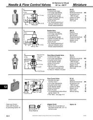
Series MKSpecificationsMedia.................................................... <strong>Air</strong>Recommended Minimum Pressure....... 20 psiDuralon ® rod bushing. .......................... See chart pg. 5.1Maximum Operating Pressure.............. 150 psiAmbient & Media Temperature.............. -25° to + 250°FPrelubrication........................................ Magnalube ® -G Grease<strong>Air</strong>line Lubrication................................. RecommendedSizing Pancake ® – <strong>Multi</strong>-<strong>Power</strong> ® <strong>Cylinders</strong>Pancake ® —<strong>Multi</strong>-<strong>Power</strong> ®5Series Stages Area Equivalent Force @ Retract BodyAvailable StrokesBore (Pistons) ‡ Bore † 60 psi Area O. D. 1/8" 1/4" 1/2" 3/4" 1" 1-1/2"2 .35 .6 20• • • • •MK 1/2 3 .50 .7 30 .15 1.13 • • • •4 .65 .9 35• •2 .80 1.0 45• • • • •MK 3/4 3 1.16 1.1 70 .36 1.50 • • • •4 1.52 1.3 90• •2 1.79 1.5 105• • • • •MK 1-1/8 3 2.59 1.8 155 .80 1.99 • • • •4 3.39 2.0 200• •2 3.83 2.2 230• • • •MK 1-5/8 3 5.59 2.6 335 1.76 2.74• •4 7.35 3.0 440• •2 5.84 2.6 350• • • •MK 2 3 8.54 3.2 510 2.70 3.24 • •4 11.24 3.7 670•2 9.38 3.3 560• • • •MK 2-1/2 3 13.85 4.0 830 4.47 3.74 • •4 18.32 4.7 1095•2 13.70 4.0 820• • • •MK 3 3 20.33 5.0 1215 6.63 4.24 • •4 26.96 5.7 1615•2 24.35 5.5 1461• • • •MK 4 3 36.13 6.7 2168 11.78 5.50 • •4 47.91 7.7 2875•‡ Area = Total effective piston area, square inches. † Equivalent Bore = Bore required for a single piston cylinder.MP-PCake 1/2Models -MK 1/2 and -MK 3/4 Models -MK 1-1/8 and -MK 1-5/8D – TappedBMounting HolesBZ(2 at each end)GGK90°F – Rod Dia.90°AH – Wrench FlatACBoltY Circle10-32 Ports w/.38 Dia. S'faceE – Female Rod ThreadFixed DimensionsSeries BoreMK 1/2MK 3/4MK 1-1/8 (Dim. B < 4.33)MK 1-1/8 (Dim. B ≥ 4.33)MK 1-5/8MK 2MK 2-1/2MK 3MK 4A1.131.501.991.992.743.243.744.245.50C0.881.191.691.692.382.813.253.815.00MP-PCake 121, 221D#6-32 x .44 dp#8-32 x .44 dp.32 C'Bore x .19 dp#10-32 x .50 dp.32 C'Bore x .19 dp.38 C'Bore x .26 dp.38 C'Bore x .26 dp.38 C'Bore x .26 dp.38 C'Bore x .26 dpJ Dia––0.20–0.200.270.270.270.27E8-32 x .38 dp10-32 x .38 dp5/16-24 x .63 dp5/16-24 x .63 dp3/8-24 x .75 dp1/2-20 x .88 dp1/2-20 x .88 dp1/2-20 x .88 dp5/8-18 x .88 dpF.25.31.50.50.62.75.75.751.00G0.130.130.140.140.140.140.140.140.20HWrenchFlatCE – FemaleYBolt Circle Rod ThreadZNote 11/8 NPT Ports MK-1 1 /8 (Dim. B < 4.33) D – C'BoredAll MK-1 5 /8MK-1 1 /8 (Dim. B≥ 4.33)F – Rod Dia.J – Thru HolesD-Tapped Mtg. Holes(2 at each end)H3/16 x .111/4 x .117/16 x .117/16 x .111/2 x .115/8 x .115/8 x .115/8 x .117/8 x .18Y0.460.46––0.520.520.640.640.705.13Specifications subject to change without notice or incurring obligation7-13-05
How to OrderModel Number CodeMK 1-1/8x 1 – 3 – 1– MRSeriesModel -MK 2BKZ1/8 NPT Ports2 StagesextendBore1/2"3/4"1-1/8"1-5/8"2"2-1/2"3"4"StrokeSee available strokesin the sizing guideon page 5.13Ordering ExamplesStagesExtendModel No: Series Bore x Stroke – Stages Extend – Stages RetractMK2 X 1-2-1Pancake ® -<strong>Multi</strong>-<strong>Power</strong> ®2" Bore, 1" Stroke, 2 Stage Extend, 1 Stage RetractMK 1-1/8 X 1/2-4-1-MRPancake ® -<strong>Multi</strong>-<strong>Power</strong> ®1 1/8" Bore, 1/2" Stroke, 4 Stage Extend, 1 StageRetract, Male RodMP-PCake 321Stroke1/81/41/211-1/21/81/41/23/41/41/2GYMK 1/2B1.882.132.883.884.882.382.883.884.883.884.88Z1.551.802.553.554.552.052.553.554.553.554.55A72°MK 3/4B1.882.132.883.884.882.382.883.884.883.884.88CBolt CircleVariable DimensionsSeries Bore3 Stagesextend4 StagesextendZ1.551.802.553.554.552.052.553.554.553.554.55B2.362.613.304.335.332.863.744.335.334.335.33K2.032.282.96note1note12.533.40note1note1note1note1D – C'BoredJ – Thru Holes (2)F – Rod Dia.HWrenchFlatMK 1-1/8E – FemaleRod ThreadY0.520.520.700.990.990.520.890.990.990.990.99Z1.521.772.453.494.492.022.893.494.493.494.49BNA3.303.804.805.80NANA4.805.804.805.80KNA2.973.474.475.47NANA4.475.474.475.47StagesRetract2 — 13 — 14 — 11 — 21 — 31 — 4Standard available combinations arelisted above. Consult factory for<strong>Multi</strong>ple Extend–<strong>Multi</strong>ple RetractOptions.MK 1-5/8ZNA2.963.464.465.46NANA4.465.464.465.46BNA3.524.025.026.02NA5.02NA6.026.02NAMP-PCake 521-1221Models -MK 2-1/2, -MK 3, and -MK4BKZ1/8 NPT PortsMK 2KNA3.133.634.635.63NA4.63NA5.635.63NAZNA3.023.524.525.52NA4.52NA5.525.52NABNA3.393.894.895.89NA4.89NA5.895.89NAGMK 2-1/2KNA3.003.504.505.50NA4.50NA5.505.50NAYSuffix Options - See pages 5.15 - 5.17Stroke Collars: 1/8" -C1; 1/4" -C2; 3/8" -C3Threaded Nose Mount: Single Rod -FDouble rod, rod end -FDouble rod, cap end -F1Double rod, both ends -F2Double Rod-DRMale rod thread: Single rod-MRDouble rod, rod end-MRDouble rod, cap end-MR1Double rod, both ends-MR2Viton seals -VExternal guide, nonrotatingfor load guiding -GFinish: ProCoat -NRubber Bumpers:1-1/8 Bores & Larger Rod end -BFCap end -BRBoth ends -BFRAdjustable extend stroke1-1/8 Bores & Larger -ASClevis mount: Ports in-line with slot -PMPorts 90° to slot-SMEye mount: Ports in-line with tang -EPMPorts 90° to tang-ESMMagnetic piston & sensor mounting slot(s) -EOrder sensors separately.Extend Port Bushing3/8 NPT for 2" Bores and Larger -E381/4 NPT Ports for 1-5/8" Bores and Larger -P14ZNA2.893.394.395.39NA4.39NA5.395.39NAA45°BNA3.453.954.955.95NA4.95NA5.955.95NAMK 3KNA3.103.554.555.55NA4.55NA5.555.55NAD – C'BoredJ – Thru Holes (4)F – Rod Dia.ZNA2.963.464.465.46NA4.46NA5.465.46NABNA3.704.205.206.20NA5.20NA6.206.20NAHWrenchFlatC – Bolt CircleE – FemaleRod ThreadMK 4KNA3.253.754.755.75NA4.75NA5.755.75NAZNA3.213.714.715.71NA4.71NA5.715.71NA56-29-05Specifications subject to change without notice or incurring obligation5.14
P'Cake - 1.20 - (5) Optn F P'Cake - 1.20 - (5) Optn FThreaded Nose Mount Option -F Available on 1/2" to 1-5/8" Bore Models3-24-983-24-981/2" & 3/4" Bores 1-1/8" & 1-5/8" Bore.38.38 + BSee page 5.13.13Pilot D Dia.x .06 longThread.75.141.00 + B .25See Page 5.131.99 ThreadPilotD Dia. x .13 longBore1/2"3/4"1-1/8"1-5/8"Pancake ® —<strong>Multi</strong>-<strong>Power</strong> ®D Pilot.495-.491.620-.6151.000 -.9951.250-1.245Thread1/2" – 205/8" –181" –141 1 /4"-12Nut is included.Nut Part No.MC-500-195MC-700-19512100-19522100-195ThreadACAC0.720.881.591.88AFTAF0.630.751.381.63T.25.25.19.255Plated steel nose mounting brackets Must be ordered separatelyBore1/2"1/2"3/4"3/4"Part No.BRK-201BRK-202BRK-301BRK-302Male Rod ThreadC1.131.131.251.25Single RodDouble Rod, Rod End OnlyDouble Rod, Cap End OnlyDouble Rod, Both EndsD.50.50.63.63F–1.80–2.25FC–0.99–1.25Option-MR-MR-MR1-MR2H1.31–1.75–HC.75–1.00–Loctite ®L.63–.69–RodLC.38–.44–T.09.09.12.12W1.501.501.801.80No ReliefNo WeaknessThreadBRK-201 & BRK-301C/2LLCD Dia.High Strength StudCW/2WT.20 Dia.HHCPart No: BRK-201BRK-202 & BRK-302LLCD Dia.C/2CW/2WT.20 Dia.HHCPart No: BRK-201BoreThread1/2" 8-32 x .503/4" 10-32 x .501-1/8" 5/16–24 x .751-5/8" 3/8–24 x .882" 1/2–20 x 1.002-1/2" 1/2–20 x 1.003" 1/2–20 x 1.004" 5/8-18 X 1.25Clevis MountOption -PM & -SMPivot Mount Option -EPM & -ESM (Available 1/2" thru 2" Bore)FGCL + Dim. BSee pages 5.13 & 5.14HAED-PM Port locationsin line with slot-SM Port locations90° to slotL + Dim. BSee pages 5.13 & 5.14CHAAED-EPM Port locationsin line with slotF-ESM Port locations90° to slotBore1/2"3/4"1-1/8"1-5/8"2"2-1/2"3"4"A.25.25.31.38.38.50.50.63AA.23.23.30.35.36NANANAC0.410.410.690.690.690.970.971.22D0.340.340.560.680.680.900.901.06E Hole.251.251.3135.376.376.501.501.626E Pin.250.250.3125.3750.3750.500.500.625F0.630.631.001.251.251.631.632.00G0.830.831.211.481.481.861.862.24H.25.25.37.37.37.50.50.63L0.560.560.941.001.001.381.381.75Pro-Coat Option -NElectroless Nickle platingConsult Engineering for specificapplication requirementsElectroless Nickel plating is a hard, smooth,corrosion & wear resistant coating that willoften suffice for applications where stainlesssteel is specified. The coating is a highnickel low phosphorous alloy deposited bychemical reduction without electric currentthat is more corrosion resistant than platednickel. Its lasting luster provides high eyeappeal. It has natural lubricity & high resistanceto abrasion. Standard hardness ofthe coating is approximately 49 RockwellC. Heat treating can increase hardness to60 Rockwell C.5.15 10-26-04Specifications subject to change without notice or incurring obligation
Series MK Option SpecificationsMagnetic Piston Option -EFor 1-1/8" Bore and larger<strong>Inc</strong>ludes Dovetail Mounting SlotsOrder Sensors SeparatelyDT Mount PCakes • 3/18/98Sensor mounts in1/4" 60° DovetailShorter stroke 2/12/98 cylinders are furnished withtwo MK dovetail Sw mounting Locn-Pan-721slots when Suffix Option"E" is specified.5/08/015/8/01 MK Sw Locn-Pan-121 5/8/0015/8/015/8/01MK1-1/8Sw Locn-Pan-221MK1-5/8 MK Sw Locn-Pan-321MK2 Sw Locn-Pan-521MK2-1/2MK3 MK Sw MK4 Locn-Pan-122172°45°A single slot on longer strokemodels has room to accommodatemultiple sensors.45°45°#2#15#240° 40° #1#245° 45° #1#235° 35° #190°90°30°#230°#1#230°30°#11/8" to 1" stroke models have 2 mounting slots. 1-1/2" stroke models have 1 slot. Ports are in-line for all Bores, all Strokes.Low Profile, Solid State,Magnetic Piston Position SensorsTemperature Range:–20° to +80°C (–4° to +176°F)Female CordsetsforQuick DisconnectLength1 Meter2 Meters5 MetersPart No.CFC-1MCFC-2MCFC-5MEncased in plastic housing, dovetail style sensorsare corrosion resistant. 60° wire outlet allows closemounting. Profile shown here is typical.Ordering Guide – Dovetail Style Magnetic SensorsCylinder ModelSeries MKSensorTypeElectronicElectronicPrewired 9 ft.Part No.949-000-031949-000-032Quick DisconnectPart No.*949-000-331949-000-332Electrical CharacteristicsSourcing, PNP, 6-24 VDC, 0.20 Amp Max current, 0.5 Voltage DropSinking, NPN, 6-24 VDC, 0.20 Amp Max current, 0.5 Voltage DropNote*: Quick disconnect style sensors are supplied with 6" pigtail. Order female cordsets separately.LEDYesYesmk dr.epsDouble RodOption -DRG + strokeStandard piston rod and rod bushingon both ends of the cylinder.BoreG1/2"0.133/4"0.131-1/8"0.141-5/8"0.142"0.142-1/2"0.143"0.144"0.20Viton Seals Option -V Use for elevated temperatures (–15° to + 400°F) orcompatibility with exotic media. Consult engineering forcompatibility information.5.17 Specifications subject to change without notice or incurring obligation1-20-08
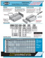
Series MQ, MQF, MQLSquare 1 ® —<strong>Multi</strong>-<strong>Power</strong> ®SpecificationsMedia.................................................... <strong>Air</strong>Recommended Minimum Pressure....... 20 psiMaximum Operating Pressure.............. 150 psiAmbient & Media Temperature.............. -25° to +250°FPrelubrication........................................ Magnalube ® -G Grease<strong>Air</strong>line Lubrication................................. RecommendedSizing Square 1 ® – <strong>Multi</strong>-<strong>Power</strong> ® <strong>Cylinders</strong>Stages Area Equivalent Force @ RetractSeries Bore(Piston) ‡ Bore † 60 psi AreaAvailable Strokes1/8" 1/4" 1/2" 3/4" 1" 1-1/2" 2" 2-1/2"5MQMQWMQFMQFWMQLMQLW3/4" 2 .80 1 48 .367/8" 2 1.12 1-3/16 67 .521-1/8" 2 1.79 1-1/2 107 .801-5/8" 2 3.83 2-1/8 229 1.762" 2 5.84 2-5/8 350 2.70• • • • •• • • • •• • • • • • •• • • • • • •• • • • • •‡ Area = Total effective piston area, square inches. † Equivalent Bore = Bore required for a single piston cylinder.How to OrderModel Number CodeMQLGW1-1/8 x 1 – 2 – 1 – DR - MR1MountingMQSide TapMQFFaceMQLSide LugRod ExtensionSingle RodModelsBlank –for standardextension perdimension "G"W - for Extensionto dimension "W"Double RodModelsBlank –"G" extensionboth endsW –"W" extensionboth endsBore3/4"7/8"1-1/8"1-5/8"2"StandardStrokes<strong>Inc</strong>hesFor strokesavailableSee chartaboveGW – "G" extension onrod end; "W" extensionon cap endWG – "W" extension onrod end; "G" extensionon cap endOrdering Example: MQL GW 1-1/8 x 1 - 2 - 1 - DR - MR1Model number code above describes Square 1 ® <strong>Multi</strong>-<strong>Power</strong> ® side lugmount cylinder with “G” rod extension on rod end; “W” rod extensionon cap end; 1-1/8" bore; 1" stroke; 2 stages extend; 1 stage retract;double rod; male rod on cap end.Stages StagesExtend Retract2 — 11 — 2Standard availablecombinations arelisted above.OPTIONSSee pages 5.20 - 5.22DescriptionSpecifyMale Rod ThreadSingle Rod-MRDouble Rod, Rod End -MRDouble Rod, Cap End -MR1Double Rod, Both Ends -MR2Viton Seals:-15° to + 400°F -VMetric Rod Thread -MPort Positions (page 5.19) -1BExternal Guide, Nonrotating -GDouble Rod-DRMagnetic piston and -Esensor mounting slot(s)Order sensors separately.6-29-05Specifications subject to change without notice or incurring obligation5.18
Square 1 ® MQ Dims 5/21/01—<strong>Multi</strong>-<strong>Power</strong> ® <strong>Cylinders</strong>MQ Series: Side Tap MountingBore availability:3/4", 1-1/8", 1-5/8", 2"PortPosition1BFHAA–21XPortPosition1AG or WYBZPE4K13K1–22A–2AMF Dims 7-17-01J (Ref.)RodEndFaceLMCapEndFaceN14 Holes5MQF Series: Face MountingBore availability:3/4", 1-1/8", 1-5/8", 2"PortPosition1B(see note)FHAA–21XPortPosition1AG or WYBZPS1S1–2R (Ref.)E4S13S1–22A–2ARodEndFace"T1" Tapped MountingHoles, MQL 2 each Dims end (See 6-27/01 note)R (Ref.)UCapEndFaceNote: When Port Position 1B isspecified, Mounting Holes T1 rotate 90°MQL Series: Side Lug MountingBore availability:7/8", 1-1/8", 1-5/8", 2"PortPosition1BFHAA–21XPortPosition1AG or WYBZPWasherT2EJ (Ref.)4K23K2–22A–2AS2J (Ref.)RodEndFaceLMCapEndFaceN24 HolesBore3/4"7/8"1-1/8"1-5/8"2"Variable DimensionsFixed DimensionsA1.251.251.502.002.50E10-32x.38dp10-32x.38dp5/16-24x.63dp3/8-24x.75dp1/2-20x.88dpF Dia..31.31.50.62.75G.13.13.19.19.19H J1/4 .191/4 .197/16 .191/2 .255/8 .25K1.88–1.131.502.00Stroke1/8"1/4"1/2"3/4"1"1-1/2"2"2-1/2K2–1.631.882.503.003/4" & 7/8" Bores 1-1/8" Bore 1-5/8" Bore 2" BoreB–2.272.773.274.275.27––L.51.51.59.66Z–1.491.992.493.494.49––N110-24x.25–10-24x.251/4-20x.315/16-18x.38M–1.251.752.253.254.25––N2–.21.21.27.27B2.693.193.69–4.695.696.697.69P10-3210-321/81/81/8R.19–.19.25.25Z1.692.192.69–3.694.695.696.69S1.88–1.131.502.00M1.502.002.50–3.504.505.506.50S2–.19.19.25.31B2.943.443.94–4.945.946.947.94Z1.882.382.88–3.884.885.886.88T11/4-20x.75dp–1/4-20x.75dp ‡1/4-20x.75dp ‡5/16-18x.75dp*M1.632.132.63–3.634.635.636.63T2–.02.02.03.03B–3.614.11–5.116.117.118.11U.75–.75.75.75Z–2.382.88–3.884.885.886.88W.38.38.381.001.00.68‡Note: 1-1/8" & 1-5/8" bores,1/8 stroke only: .20 Dia. thru, .32 dia. C'Bore x .19 deep for #10 SHCS and 1/4-20 x .75 deep tapped mounting holes, 2 places each end*Note: 2" bore,1/4 stroke only: .27 Dia. thru, .38 dia. C'Bore x .26 deep for 1/4" SHCS and 5/16-18 x .75 deep tapped mounting holes, 2 places each endX.31.31.28.31.38M–2.252.75–3.754.755.756.75Y.39.39.50.54.625.19 Specifications subject to change without notice or incurring obligation1-20-08
Series MQF Mounting KitsMating EyeBracketRod ClevisEye BracketClevis BracketBore3/4"1-1/8"1-5/8"2"2"StrokeAllAllAll1/41/2 UpRod EndRod ClevisEnglishRC-19RC-31RC-38RC-54RC-56MetricMRC-19MRC-31MRC-38MRC-54MRC-56MatingEye Bkt.EM-02EM-04EM-121EM-121EM-121ClevisBracketPM-04PM-121PM-221PM-321PM-321Cap EndEyeBracketEM-04EM-121EM-221EM-321EM-321Trunnion Mount KitMountingScrews2 <strong>Inc</strong>ludedA/2Rod ClearanceALB/2BccD Dia.EFJJBore3/4"1-1/8"1-5/8"2"MaterialsBracket: High strength Zinc die castingPivot Pins: Precision dowel pinsMounting screws: 4, Steel, plated or black oxidedKit No.TR-04TR-121TR-221TR-321A1.251.502.002.50B2.002.503.003.75C.25.31.31.31D.1253.2503.2503.2503E.25.31.44.44F.50.63.81.94J.07.06.06.06L.38.50.63.755Clevis Bracket KitNFBC K ADHLIJEPart #PM-04PM-121PM-221PM-321MA1.251.502.002.50B0.631.001.251.25C0.630.881.251.25MaterialsBracket: High strength Zinc die castingBushings: Oil filled powdered metalPin: 416 Stainless SteelClips: 2, Plated steelScrews: 4, Steel, plated or black oxidedD0.250.310.380.38E Pin.250.3125.375.375E Hole.251.3135.376.376F0.831.211.481.48H.16.25.31.31I0.560.941.001.00J0.811.321.381.38K0.881.131.502.00L.30.46.52.52M.41.69.69.69N1/4-20x.751/4-20x.751/4-20x1.005/16-18x1.00Eye Bracket KitKAN L MDKHEAIJRod Clevis 6-22-01Part #EM-02EM-04EM-121EM-221EM-321A1.251.251.502.002.50MaterialsBracket: High strength Zinc die castingBushings: Oil filled powdered metalScrews: 4, Steel, plated or black oxided.*Special 1/4-20 with #13 Phillips HeadD.18.23.30.36.36E.1885.251.3135.376.376H.16.16.25.31.31I0.560.560.941.131.13J0.870.871.381.691.69K0.880.881.131.502.00L.31.31.44.56.56M.36.41.69.81.81N1/4-20x.75 FHMS*1/4-20x.75 FHMS*1/4-20x.75 FHMS*1/4-20x1.00 FHMS*5/16-18x1.00 FHscsRod Clevises7-17-01PIJMLDE PinFCPart #RC-19,MRC-19RC-31, MRC-31RC-38, MRC-38RC-54, MRC-54RC-56, MRC-56MaterialsClevis and Stud: Steel, black oxidedPin: 416 Stainless SteelClips: Steel, platedC0.500.751.001.001.00D.19.25.32.32.32E PIN.1870.2495.3120.3120.3120F0.700.961.211.211.21Specifications subject to change without notice or incurring obligationI0.750.881.251.311.31J1.001.161.631.691.69L.33.39.61.61.61M.38.50.63.63.63P English10-32x.255/16-24x.383/8-24x.371/2-20x.391/2-20x.62P MetricM5x6.3mmM8x9.7mmM10x9.4mmM12x9.9mmM12x15.7mm5.20
Square 1 ® —<strong>Multi</strong>-<strong>Power</strong> ® <strong>Cylinders</strong>5Flange Mounting Kits for Series MQF and MQFWFlange Style 7ER411B4A4B3ATF4XA Sq. G †3TF2UF1A2B2A3B2FB2 Dia.2 PlacesFB4 Dia.4 PlacesSeries MQFFlange Style 8 & 9A Sq. XW ‡1 1ASeries MQFW1B4A2BER44B3A3TFUF2A3B2FB Dia.4 PlacesFFFlange Bore <strong>Fabco</strong> Mounting Hole PatternStyle Size Kit No. Interchange Information4 Hole PatternC&C: 1-1/8" Bore, Series T, F, & R7 3/4" H7-04Mosier: 1-1/8" Bore, Series TAV, 8 & 9PHD: 1-1/8" Bore, Series AV, RF, & CF2 Hole PatternCompact <strong>Air</strong>: 3/4" Bore, Style S, FF, & RF4 Hole PatternC&C: 1-1/8" Bore, Series T, F, & R7 1-1/8" H7-121 Mosier: 1-1/8" Bore, Series TAV, 8 & 97 1-5/8 H7-221PHD: 1-1/8" Bore, Series AV, RF, & CF2 Hole PatternCompact <strong>Air</strong>: 1-1/8" Bore, Style S, FF, & RF4 Hole PatternNFPA COde MF1 & MF2 for 1-1/2" BoreAll brands conforming to this code2 Hole PatternCompact <strong>Air</strong>:1-5/8" Bore, Style S, FF, & RF4 Hole Pattern8 2" H8-321 NFPA COde MF1 & MF2 for 2" Bore9 2" H9-321All brands conforming to this code4 Hole PatternCompact <strong>Air</strong>:2" Bore, Style S, FF, & RFKits include Flange and 2 Flange Mounting ScrewsPort Positions 1A Standard all models. • To achieve 2A, 3A or 4A, rotate flange.• For 1B, specify Option -1B • For 2B, 3B, or 4B: Specify Option -1B and rotate flangeSQFW-121-1 1/2with H7-121Bore3/4"1-1/8"1-5/8"2"2"Model04121221321321Style77789Kit #H7-04H7-121H7-221H8-321H9-321A1.251.502.002.502.50E1.501.502.002.502.50F.25.25.38.38.38FBNANANA.38.38FB2.22.22.22NANAFB4.22.22.31NANAG†.13.19.19.19.19R1.001.001.431.842.00TFNANANA3.383.00TF21.752.002.50NANATF42.002.002.75NANAUF2.502.503.384.133.50W‡.38.381.001.001.00X.38.56.69.81.81External Guide, NonrotatingOption -G5.21AASquareRef.B(See page 5.19)BBJJ Square Guide PinsHard Chrome Plated SteelCCDD __2Superior nonrotating piston rod feature forapplications such as package placement,figure stamping, and any application whereanti-rotation and registration are critical asthe piston is extended and retracted.A mounting block is bolted to the pistonrod. This block has two square pins mountedto it which in turn pass through guideblocks mounted on the sides of the cylinder.• Square guide pins are hard chrome platedClearance in Guide BlockMounting Holes allow foradjustment to compensatefor wearDDMounting BlockClear Anodized AluminumGuide Block Hard Anodized AluminumGGHHEE __2Specifications subject to change without notice or incurring obligationEEFFKK MountingHoles 2 Placessteel for long wear and corrosion resistance.• Guide blocks are hard anodized aluminum forlong wear and corrosion resistance.• Clearance in guide block mounting holesprovide for adjustment and backlash control,compensation for wear, and minimal rotation.• Extended distance between guides providessuperior nonrotation and support.• Extended piston rod provides clearance betweencylinder and guide bar mounting block toeliminate pinch points.Mounting Series MQ or MQFBore 3/4" 1 1/8" 1 5/8" 2"AA 1.25 1.50 2.00 2.50BB .63 .69 .69 .69CC .63 .63 .63 .75DD 1.94 2.26 2.75 3.25EE .87 1.06 1.50 1.88FF 2.19 2.50 3.00 3.50GG .63 .63 .75 1.00HH 1.00 1.00 1.00 1.00JJ .19 .25 .25 .25KK #6-32 #8-32 1/4-20 5/16-186-29-05
Magnetic PistonOption-E<strong>Inc</strong>ludes Dovetail Mounting SlotsOrder Sensors Separately• Dovetail style sensors are actuatedby a magnetic piston.• Sensor dovetail slides into a matingslot on the cylinder body, is positionedas desired, and locked in place with aslotted set screw.• Magnetic piston and 1/4" Dovetailmounting slot(s) are specified with SuffixOption "E" in the model number.• Order sensors separately.Series MQ, MQF & MQL Option SpecificationsSensor slots atpositions #2 and #4Sensor slot atposition #2 only#4StrokeSQ Dovetails5/21/01Rod EndPort#2SQF Dovetails2/22/98Sensor stick-out:3/4" Bore = .07"Other bores = .14".14" Ref. to60° wire outletMQ Profile MQF Profile MQL ProfileSQL Dovetails1/28/98Standard Stroke & Slot Location GuideMQ (Side Tap) MQF (Face Mount) MQL (Side Lug)3/ 4" 1 1 / 8" 1 5 / 8" 2" 3/ 4" 1 1 / 8" 1 5 / 8" 2" 7/ 8" 1 1 / 8" 1 5 / 8" 2"1/8 – ✓ ✓ – – ✓ ✓ – – ✓ ✓ –1/4 ✓ ✓ ✓ ✓ ✓ ✓ ✓ ✓ ✓ ✓ ✓ ✓1/2 ✓ ✓ ✓ ✓ ✓ ✓ ✓ ✓ ✓ ✓ ✓ ✓3/4 ✓ ✓ ✓ ✓ ✓ ✓ ✓ ✓ ✓ ✓ ✓ ✓1 ✓ ✓ ✓ ✓ ✓ ✓ ✓ ✓ ✓ ✓ ✓ ✓1-1/2 ✓ ✓ ✓ ✓ ✓ ✓ ✓ ✓ ✓ ✓ ✓ ✓2 – ✓ ✓ ✓ – ✓ ✓ ✓ – ✓ ✓ ✓2-1/2 – ✓ ✓ ✓ – ✓ ✓ ✓ – ✓ ✓ ✓5Low Profile, Solid State,Magnetic Piston Position SensorsFemale CordsetsforQuick DisconnectLength1 Meter2 Meters5 MetersPart No.CFC-1MCFC-2MCFC-5MEncased in plastic housing, dovetail style sensorsare corrosion resistant. 60° wire outlet allows closemounting. Profile shown here is typical.Dovetail Style Magnetic SensorsTemperature Range: 20° to +80°C(–4° to +176°F)Cylinder ModelSeries MQ,MQF & MQLSensorTypeElectronicElectronicPrewired 9 ft.Part No.949-000-031949-000-032Quick DisconnectPart No.*949-000-331949-000-332Electrical CharacteristicsSourcing PNP 6-24 VDC, 0.20 Amp Max current, 0.5 Voltage DropSinking NPN 6-24 VDC, 0.20 Amp Max current, 0.5 Voltage DropNote*: Quick disconnect styles are supplied with 6 inch pigtail with male connector. Order female cordsets separately.LEDYesYesMale Rod ThreadOptionSingle Rod-MRDouble Rod, Rod End Only -MRDouble Rod, Cap End Only -MR1Double Rod, Both Ends -MR2St'd <strong>Inc</strong>h Thread10-32 x .5010-32 x .505/16-24 x .753/8-24 x .881/2-20 x 1.00Metric Rod Thread Option -MBore Female Rod Thread Pitch Male Rod Thread x Length3/4 M5 0.8 M5 x 12.77/8 M5 0.8 M5 x 12.71-1/8 M8 1.25 M8 x 19.01-5/8 M10 1.50 M10 x 22.22 M12 1.75 M12 x 25.4Double Rod2-13-08Option -DRBlank– "G" both ends.W– "W" extension both ends.GW– "G" extension rod end;"W" extension cap end.WG– "W" extension rod end;"G" extension cap end.SQ Rod Xtns 1/28/98G or WRod EndG or W + StrokeCap EndSpecifications subject to change without notice or incurring obligationRod Extension DimensionsBore 3/ 4 " 7/ 8 " 1 1 / 8 " 1 5 / 8 " 2"G .13 .13 .19 .19 .19W .38 .38 .38 1.00 1.005.22
Series MLR & MLSSpecificationsMedia...................................................<strong>Air</strong>Recommended Minimum Pressure......20 psiMaximum Operating Pressure.............150 psiAmbient & Media Temperature.............–25° to +250°FPrelubrication.......................................Magnalube ® -G Grease<strong>Air</strong>line Lubrication................................RecommendedHow to Order5Model Number CodeMLR 2SeriesMLRRound headMLSSquare headBore22-1/2"3"4"Ordering ExampleMountingMLS3 x 3 – 2 – 1 – PM – MRSquare head series, 3" bore, 3" stroke, 2 stages extend, 1 stageretract, clevis mount ports in-line with slot , male rod threadSizing Longstroke – <strong>Multi</strong>-<strong>Power</strong> ® <strong>Cylinders</strong>Series Bore Stages Area Equivalent Force @ Retract(Pistons) ‡ Bore † 60 psi Area2 5.84 2.6 3502" 3 8.54 3.2 512 2.74 11.24 3.7 6742 9.38 3.3 562MLR 2 1/2" 3 13.85 4.0 831 4.474 18.32 4.7 1099MLS2 13.70 4.0 8223" 3 20.33 5.2 1219 6.634 26.96 5.7 16172 24.35 5.5 14614" 3 36.13 6.7 2167 11.784 47.91 7.7 2874‡ Area = Total effective piston area, square inches.† Equivalent Bore = Bore required for single piston cylinder.–x 3 – 2 – 1StrokeStandard strokes:1/2", 1", 1-1/2", 2",2-1/2", 3", 4", 5", 6"(Optional – any otherstroke 0" thru 12")Stages StagesExtend Retract2 — 13 — 14 — 11 — 21 — 31 — 4Standard availablecombinations are listedabove. Consult factory for<strong>Multi</strong>ple Extend–<strong>Multi</strong>pleRetract Options.Extended Tie RodsRod end only . . . . . . . . . . .–WFCap end only . . . . . . . . . . –WRRod and Cap Ends ..... –WFRClevis MountRound head onlyPorts in-line with slot . . . . .–PMPorts 90° to slot . . . . . . . . .–SM–PM – MROPTIONSSee pages 5.11, 5.25 - 5.28DescriptionSpecifyDouble Rod-DRNonrotating Single Rod ‡-NRNonrotating Double Rod ‡-NRDRMale Rod ThreadSingle Rod-MRDouble Rod, Rod End-MRDouble Rod, Cap End-MR1Double Rod, Both Ends-MR2Viton Seals (-15° to +400°F) -VShock & Speed Control using hydraulics ‡ -HSRubber BumpersRod End-BFCap End-BRBoth Ends-BFRAdjustable Extend Stroke-AS3/8 NPT Ports in Heads -P38High Flow Vents-HFPort Positions All PortsPosition #1StandardPosition #2-PA2Position #3-PA3Position #4-PA4Rod End Position #1 StandardPosition #2-PR2Position #3-PR3Position #4-PR4Cap End Position #1 StandardPosition #2-PC2Position #3-PC3Position #4-PC4Atmospheric Vent or Ported Baffle PortPosition #1StandardPosition #2-PB2Position #3-PB3Position #4-PB4Any port or vent not specified will be inPosition #1 as shown on page 5.24Magnetic Piston ‡ -Efor reed switches and Electronic Sensors(Order Sensors separately)‡ Note: Additional cylinder length requiredfor Nonrotating Rods 0.50"for Option -HS (see page 5.11) 0.50"for Option -E 1.00"5.23Specifications subject to change without notice or incurring obligation2-25-08
Longstroke —<strong>Multi</strong>-<strong>Power</strong> ® <strong>Cylinders</strong>Series MLR – Round Head, Standard, Face Mount, Rod and Cap End90° 12" Bore 2-1/2" Bore3" Bore4" Bore2.81 BC4K Female30° 22.5° 21.5°Rod Thread1113.25 BC443.81 BC0.251/2" Hex Nut5.00 BCF Rod Dia.(Number of stages timesstroke) + Dimension B0.50 0.501/4 NPT 1/4 NPT3 2223.33 Dia..33 Dia.3.33 Dia. .33 Dia.3HA21.001.00Series MLS – Square Head,Standard, Side Tap MountNote:1) 2"Bore – Ports at Position #3NOT available.2) 2-1/2, 3 & 4 Bores –3/8 NPT Ports (-P38) at Position #3NOT available.Rod EndPortTHNT42" Bore2.190.8113TNE2-1/2", 3", & 4" Bores0.25K FemaleThreadCap EndC1/2Port 1Hex Nut2ETHNT43HTNE2FRod Dia.R(Number of stages timesstroke) + Dimension B0.50 0.501/4 NPT 1/4 NPT1.001.005RExtended Tie Rod Mount forRound and Square Head Models- WF Rod End Only-WR Cap End Only-WFR Rod and Cap Ends2" Bore3 Tie Rodsequally spacedZ2-1/2", 3", & 4" Bores4 Tie Rodsequally spacedZRod EndCap End2.190.81BCCap EndPortBCWF5/16-24 ThreadWRRod EndPortTHBCBCWF5/16-24 ThreadWRDimensionsBore2"2-1/2"3"4"A3.253.754.255.50B2 stage3.423.423.423.42B3 stage4.274.274.274.27B4 stage5.125.125.125.12BC2.813.253.814.63CNA1.751.752.25E3.003.503.504.50F0.750.750.751.00H5/8 x .255/8 x .255/8 x .257/8 x .25K1/2-20 x .75 dp1/2-20 x .75 dp1/2-20 x .75 dp1/2-20 x .75 dpNT5/16-18 x .62 dp3/8-16 x .75 dp1/2-13 x 1.00 dp1/2-13 x 1.00 dpR0.440.380.500.50TH1.381.751.752.25TN0.881.251.502.06WF1.31.31.41.4WR1.31.31.41.4Z60°30°22.5°23.5°1-21-08Specifications subject to change without notice or incurring obligation5.24
Longstroke —<strong>Multi</strong>-<strong>Power</strong> ® <strong>Cylinders</strong>Round Head Clevis MountSpecify mounting optionPorts in line with slotPorts 90° to slotPivot pin and retaining lockringsare included as standard.Accessories: See page 5.27Eye Bracket KitsRod ClevisesOption-PM-SMEEFFJJBore2"2-1/2"3"4"B0.751.001.001.25EE1.251.631.632.00FF.38.50.50.63-PM Port locationsin line with slotGG Pin.3745.4995.4995.6245GG Hole.376.501.501.626HH0.690.970.971.22JJ1.481.861.862.24M.38.50.50.6350.25mp LS dr.epsBHHMGG-SM Port locations90° to slotOil filled powdered metalPivot Pin Bushings are standard.Pivot Pin, 416 stainless steelLockrings, plated steelDouble RodOption -DR.25 + StrokeTypical for all boresall mounting stylesStandard piston rod and rod bushing on both endsof the cylinder.Use when attachment to both ends of the cylinderis required, or to indicate piston position location.Also see Option –E on page 5.28.Male Rod ThreadSingle RodDouble Rod, Rod End OnlyDouble Rod, Cap End OnlyDouble Rod, Rod & Cap EndsRodOption-MR-MR-MR1-MR2No ReliefNo WeaknessA high strength stud is threaded into thestandard female rod end and retained withLoctite ® . This method eliminates the smalldiameter thread relief area normally requiredwhen machining male threads. This providesa much stronger rod end which can berepaired, rather than replacing the completerod, should the thread be damaged.Loctite ®ThreadStudThreadBoreThread2" 1/2–20 x 1.002 1/2" 1/2–20 x 1.003" 1/2–20 x 1.004" 1/2–20 x 1.00Rubber BumpersRod End onlyCap End onlyBoth Rod & Cap EndsOption-BF-BR-BFRRubber BumpersA rubber doughnut is bonded to thecylinder head to act as the piston stopand absorb the impact of the piston. Thisreduces noise and absorbs energy, thusreducing damage to the cylinder andtooling due to pounding.Standard rubber mass will compressand give full stroke at 60 to 80 psi. Thismass can be adjusted to meet yourspecific pressure and/or dynamic loadrequirements requirements5.25 Specifications subject to change without notice or incurring obligation6-29-05
Series MLR & MLS Option Specificationsadjustable extend strokeOption -ASAvailable all Bores.For strokes through 6"Full stroke adjustment is standard.Note!To maintain operator safety featuresof this option, it is NOT available withmounting styles: -WR and -WFR.Use caution when mounting to avoidcreating pinch points.Note: NOT available with mounting styles–PM and –SMBD + StrokeBADiameterBC + (2 x Stroke)BE + StrokeBB DiameterBFStroke adjustmentper revolutionSee complete description on page 5.9.Bore 2" 2-1/2" 3" 4"BA 1.50 1.50 1.50 2.00BB 2.00 2.00 2.00 2.00BC 1.65 1.65 1.65 1.42BD 0.75 0.75 0.75 0.50BE 0.75 0.75 0.75 0.75BF .063 .063 .063 .063+ (2 x Stroke)+ Stroke3/8 NPT Ports in Heads Option -P38Use 3/8 NPT ports for higher flows,air over oil systems, etc.5Nonrotating RodOption -NRA stainless steel hex rod and a hexbroached bushing of SAE 660 bearingbronze replaces the standard roundrod and bushing.A ported baffle is used so the pistonassembly can be retracted by the nextpiston back from the rod end. Thenormal rod head port becomes anatmospheric vent. The tolerance onrotation is ±1°.The hex rod design does allow forsome torque loading on the shaft.However, torque loads that induce sideloading should be minimized for bestoverall life and performance.Hex rod flats have Random Rotationrelative to Mounting PatternHex RodNo rodsealVHVCAtmospheric Ventfor all extend/retractcombinationsRetract Portin BaffleB + [ See Chart ]See page 5.24 for Dimension “B”.No. of TotalAvailable Ported No. ofCombinations Baffles Stages2 – 1 1 23 – 1 1 33 – 2 2 34 – 1 1 44 – 2 2 44 – 3 3 4Add to HexDimension “B” Rod 3/8 NPT PortsRetract for each Across St'd Ports (–P38)Bore Port Ported Baffle Flats VC VH max VC VH max2" 1/4 NPT .50" .75" .65 .69 .80 1.562-1/2" 1/4 NPT .50" .75" .65 .69 .80 1.563" 1/4 NPT .50" .75" .65 .69 .80 1.564" 1/4 NPT .50" 1.00" .65 .69 .80 1.56Nonrotating Double RodOption-NRDRA combination of the Options –NRand –DR as shown above. The rodend rod is Hex and the cap endrod is round. The ported baffles areincluded and the “Dimension B” adjustmentsshown for Option –NR must bemade. Extend piston areas must also bereduced by the rod area.High Flow Vents Option -HF The atmospheric vent in the baffleis cut larger to provide less resistanceto the air flow.Use when higher cycle speeds arerequired.Viton Seals Option -V Use for elevated temperatures(–15° to + 400°F) or compatibilitywith exotic media.2-6-08Specifications subject to change without notice or incurring obligationConsult engineering for compatibilityinformation.5.26
Longstroke —<strong>Multi</strong>-<strong>Power</strong> ® <strong>Cylinders</strong>End Lug Mount KitKit includes:2 Brackets and4 bolts for attachingthe brackets to thecylinder heads.Materials:Brackets, steel, platedScrews, steel, black oxideAT3AH24AB 6 Holes1WBore2"2-1/2"3"4"W/2 S/2SAOKit No.EL-20EL-25EL-30EL-40S1.752.252.753.50(Number of stages timesstroke) + Dim. XA(Number of stages timesstroke) + Dim. SAW2.503.003.504.50AB.41.41.53.53AH1.632.002.132.63AO.44.44.56.56AT.25.25.38.38AOSA2 stage4.044.164.664.66SA3 stage4.895.015.515.51SA4 stage5.745.866.366.36XA2 stage3.984.044.294.29XA3 stage4.834.895.145.14XA4 stage5.685.745.995.9953Side Lug Mount Kit – Brackets may be mounted in two different positions as shown –(Number of stages timesKit includes:stroke) + Dimension XE12 Brackets andLHLHSB 4 Holes4 bolts for attaching4the brackets to the4US/2 TS/2cylinder heads.US/2 TS/231Materials:1US TSBrackets, steel, platedUS TS2Screws, steel, black2oxideSTBore2"2-1/2"3"4"Kit No.SL-20SL-25SL-30SL-40EO1EO1.50.50.56.56EO20.500.631.191.19Rod Clevis 6-22-01(Number of stages timesstroke) + Dimension SS1LH1.632.002.132.63SB.41.41.53.53EO1ST(Number of stages timesstroke) + Dim. XE2EO2SB 4 Holes(Number of stagestimes stroke)+ Dim. SS2Position #1 Position #2SS1 SS1 SS1 XE1 XE1 XE1SS2 SS2 SS2 XE2 XE22 stage 3 stage 4 stage 2 stage 3 stage 4 stage ST TS US 2 stage 3 stage 4 stage 2 stage 3 stage2.66 3.51 4.36 3.29 4.14 4.99 .25 3.75 4.50 2.42 3.27 4.12 3.17 4.022.92 3.77 4.62 3.42 4.27 5.12 .25 4.25 5.00 2.42 3.27 4.12 3.17 4.023.54 4.39 5.24 3.73 4.58 5.43 .38 4.75 5.88 1.29 2.14 2.99 2.60 3.453.54 4.39 5.24 3.73 4.58 5.43 .38 5.50 6.63 1.29 2.14 2.99 2.60 3.45EO2XE24 stage4.874.874.304.30Rod ClevisesPIJMLD FE PinCMaterialsClevis and Stud: Steel, black oxidedPin: 416 Stainless SteelClips: Steel, platedBore2", 2-1/2", 3" & 4"Part #RC-56C1.00D.32E PIN.3120F1.21I1.31J1.69L.61M.63P1/2-20x.62Mating Eye BktEM-121Eye Bracket Kits mate with Option -PM or -SM and Rod ClevisN L MCBK AEDHIJBore2"2-1/2", 3"4"Rod Clevis RC-56Part #EM-321EM-521EM-1221EM-121MaterialsBracket: High strength Zinc die castingBushings: Oil filled powdered metalScrews: 4, Steel, plated or black oxidedA2.502.002.501.50B2.502.002.251.50C2.001.381.501.13D.36.47.58.30E.376.501.626.3135H.31.38.38.25I1.131.501.630.94J1.692.252.631.38K2.001.381.751.13L0.560.751.000.44M0.811.131.100.69N5/16-18x1.00FHSCS5/16-18x1.00FHSCS5/16-18x1.00FHSCS1/4-20X.75 FH(#12)MS5.27Specifications subject to change without notice or incurring obligation2-13-08
Series MLR & MLS Option SpecificationsSuffix Option ESpecifies Magnetic Piston(Order Sensors and Sensor Clamps Separately)• Option -E consists of a magnet bonded into the piston head. Whenthe piston magnet moves past an external sensor, the magnetic fieldactivates the sensor without physical contact.Quick DisconnectSensor Shown2-1/2" bore model shown with2 prewired electronic sensorsand mounting clamps2-Piece Sensor Clamp shownwith quick disconnect sensorsnapped in placeSocket Head ScrewWARNINGThis cylinder is equipped with a MagneticPiston for use with Magnetically OperatedSensors. Other Magnetic SensitiveDevices Should be Kept at a Distance toAvoid Inadvertent Operation.• Mounting – The sensor snaps into a 2-part clamp that attachesrigidly to any of the tie rods and can be positioned anywhere alongthe length of the cylinder.• Reliability – The annular piston magnet is permanently bondedinto a groove in the piston. It is a polarized permanent magnet ofrubber bonded barium ferrite that is very stable and is not affected byshock. Under normal usage it will remain magnetized indefinitely.• Warning – External magnetic fields and/or ferrous objects mayaffect the strength of the piston magnet therefore affecting sensoractuation and piston position indication. Warning labels (shown left)are affixed to the cylinder.• Please note there is an increase in base length of thecylinder to accomodate the magnet. Add 1.00" to Dimension'B' on pages 5.24.Sensor Clamp Stick Out DimensionsModel3.9 RndMLR2ClampMLS2StickoutMLR2-1/2 MLS2-1/2 3.9 MLR3 SQ MLS3 Clamp MLR4 Stickout MLS4T .50" .50" .50" .10" TOP .50" VIEW .30 .30" .30"TOP VIEW5TClampSensorPistonClampPistonSensorFemale Cordsets availablein 1, 2, & 5 meter lengths9 foot prewired sensorTPiston RodCylinder TubeMagnet, RubberBonded Barium FerriteTie Rod,StainlessSteelTop View Round Head StyleCylinderHeadTie Rod,StainlessSteelPiston RodCylinder TubeCylinder HeadMagnet, RubberBonded Barium FerriteTop View Square Head StyleTSensor & Clamp Ordering GuideTemperature Range: –20° to + 80°C (–4° to + 176°F)LED Lighted Magnetic Piston Position Sensors7-5-05ProductTypeReed SwitchElectronicElectronicPrewired9 ft. Part No.9-2A197-10049-2A197-10339-2A197-1034Quick DisconnectPart Number.9-2A197-13049-2A197-13339-2A197-1334Female Cordsets for Quick DisconnectFor all MLS & MLR Models Order Part Number 800-200-000Electrical Characteristics5-120 VDC/VAC, 0.5 Amp Max., 10 Watt Max., SPST N.O., 3.5 Voltage DropSourcing, PNP, 6-24 VDC, 0.5 Amp Max., 1.0 Voltage DropSinking, NPN, 6-24VDC, 0.5 Amp Max., 1.0 Voltage DropLength 1 Meter 2 Meter 5 MeterPart Number CFC-1M CFC-2M CFC-5MSensor Mounting Clamp - for all MLS & MLR ModelsSpecifications subject to change without notice or incurring obligationWarning!Do not exceed sensor ratings.Permanent damage to sensormay occur.<strong>Power</strong> supply polarity Mustbe observed for proper operationof sensors.See wiring diagrams includedwith each sensor.5.28