Integrated Camera Motion Compensation by Real-Time Image ...
Integrated Camera Motion Compensation by Real-Time Image ...
Integrated Camera Motion Compensation by Real-Time Image ...

Create successful ePaper yourself
Turn your PDF publications into a flip-book with our unique Google optimized e-Paper software.
Abstract— This paper presents the concept of a smart<br />
satellite pushbroom imaging system with internal compensation<br />
of attitude instability effects. The compensation is performed<br />
within the optical path <strong>by</strong> an active opto-mechatronic<br />
stabilization of the focal plane image motion in a closed loop<br />
system with visual feedback. Residual distortions are corrected<br />
<strong>by</strong> image deblurring through deconvolution. Both corrective<br />
actions are derived from a real-time image motion<br />
measurement which is based on an auxiliary matrix image<br />
sensor and an onboard optical correlator. The paper describes<br />
the principles of operation, the main system elements and gives<br />
detailed performance figures derived from a simulation<br />
performance model, which contains all relevant components of<br />
the smart imaging system.<br />
R<br />
<strong>Integrated</strong> <strong>Camera</strong> <strong>Motion</strong> <strong>Compensation</strong> <strong>by</strong> <strong>Real</strong>-<strong>Time</strong> <strong>Image</strong><br />
<strong>Motion</strong> Tracking and <strong>Image</strong> Deconvolution<br />
I. INTRODUCTION<br />
EMOTE sensing cameras on satellites need a highly<br />
stable attitude of the hosting observation platform. So<br />
called scan cameras with linear image sensors use the<br />
Earth image motion in the focal plane (caused <strong>by</strong> the<br />
satellite orbital motion) to scan the image along the flight<br />
direction. Focal plane attitude stability during the scanning<br />
motion is very essential for the image quality. Attitude<br />
perturbations disturb the image motion, what results in a<br />
degradation of the modulation transfer function (MTF) and<br />
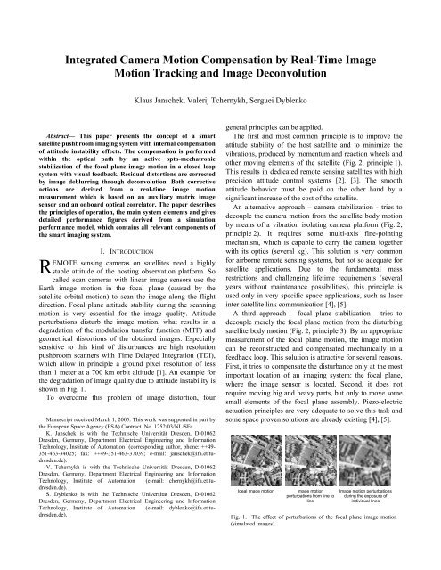
geometrical distortions of the obtained images. Especially<br />
sensitive to this kind of disturbances are high resolution<br />
pushbroom scanners with <strong>Time</strong> Delayed Integration (TDI),<br />
which allow in principle a ground pixel resolution of less<br />
than 1 meter at a 700 km orbit altitude [1]. An example for<br />
the degradation of image quality due to attitude instability is<br />
shown in Fig. 1.<br />
To overcome this problem of image distortion, four<br />
Manuscript received March 1, 2005. This work was supported in part <strong>by</strong><br />
the European Space Agency (ESA) Contract No. 1752/03/NL/SFe.<br />
K. Janschek is with the Technische Universität Dresden, D-01062<br />
Dresden, Germany, Department Electrical Engineering and Information<br />
Technology, Institute of Automation (corresponding author, phone: ++49-<br />
351-463-34025; fax: ++49-351-463-37039; e-mail: janschek@ifa.et.tudresden.de).<br />
V. Tchernykh is with the Technische Universität Dresden, D-01062<br />
Dresden, Germany, Department Electrical Engineering and Information<br />
Technology, Institute of Automation (e-mail: chernykh@ifa.et.tudresden.de).<br />
S. Dyblenko is with the Technische Universität Dresden, D-01062<br />
Dresden, Germany, Department Electrical Engineering and Information<br />
Technology, Institute of Automation (e-mail: dyblenko@ifa.et.tudresden.de).<br />
Klaus Janschek, Valerij Tchernykh, Serguei Dyblenko<br />
general principles can be applied.<br />
The first and most common principle is to improve the<br />
attitude stability of the host satellite and to minimize the<br />
vibrations, produced <strong>by</strong> momentum and reaction wheels and<br />
other moving elements of the satellite (Fig. 2, principle 1).<br />
This results in dedicated remote sensing satellites with high<br />
precision attitude control systems [2], [3]. The smooth<br />
attitude behavior must be paid on the other hand <strong>by</strong> a<br />
significant increase of the cost of the satellite.<br />
An alternative approach – camera stabilization - tries to<br />
decouple the camera motion from the satellite body motion<br />
<strong>by</strong> means of a vibration isolating camera platform (Fig. 2,<br />
principle 2). It requires some multi-axis fine-pointing<br />
mechanism, which is capable to carry the camera together<br />
with its optics (several kg). This solution is very common<br />
for airborne remote sensing systems, but not so adequate for<br />
satellite applications. Due to the fundamental mass<br />
restrictions and challenging lifetime requirements (several<br />
years without maintenance possibilities), this principle is<br />
used only in very specific space applications, such as laser<br />
inter-satellite link communication [4], [5].<br />
A third approach – focal plane stabilization - tries to<br />
decouple merely the focal plane motion from the disturbing<br />
satellite body motion (Fig. 2, principle 3). By an appropriate<br />
measurement of the focal plane motion, the image motion<br />
can be reconstructed and compensated mechanically in a<br />
feedback loop. This solution is attractive for several reasons.<br />
First, it tries to compensate the disturbance only at the most<br />
important location of an imaging system: the focal plane,<br />
where the image sensor is located. Second, it does not<br />
require moving big and heavy parts, but only to move some<br />
small elements of the focal plane assembly. Piezo-electric<br />
actuation principles are very adequate to solve this task and<br />
some space proven solutions are already existing [4], [5].<br />
Ideal image motion <strong>Image</strong> motion<br />
perturbations from line to<br />
line<br />
<strong>Image</strong> motion perturbations<br />
during the exposure of<br />
individual lines<br />
Fig. 1. The effect of perturbations of the focal plane image motion<br />
(simulated images).
disturbance<br />
torques Smart Imaging System<br />
Attitude<br />
Control<br />
System<br />
Satellite<br />
Dynamics &<br />
Kinematics<br />
Satellite<br />
Attitude<br />
Sensor<br />
Principle 1<br />
Satellite stabilization<br />
<strong>Camera</strong><br />
Pointing<br />
System<br />
<strong>Camera</strong><br />
Dynamics &<br />
Kinematics<br />
<strong>Camera</strong><br />
Pointing<br />
Sensor<br />
Principle 2<br />
<strong>Camera</strong> stabilization<br />
Fig. 2. <strong>Image</strong> stabilization principles for a remote sensing satellite.<br />
In a fourth step, a further image quality improvement can<br />
be achieved <strong>by</strong> appropriate image data refinement<br />
algorithms (Fig. 2, principle 4). All these algorithms rely on<br />
additional information on image motion, at least some apriori<br />
information on the expected disturbance motion has to<br />
be provided [6].<br />
The three basic principles 1 to 3 of active motion<br />
compensation can be categorized more generally as<br />
hierarchical coarse/fine pointing control. Such control<br />
structures are well known from biological systems, such as<br />
the very efficient coarse head/body motion control paired<br />
with the fine retina control [7], [8]. In mechatronic systems<br />
two realization variants are commonly used. The first one<br />
uses a single actuator in a cascaded control loop with a high<br />
bandwidth inner loop (velocity or relative position control)<br />
and a low bandwidth outer loop with high accuracy<br />
feedback signals [9]. The second variant uses two actuators<br />
in parallel: a low-bandwidth large stroke (coarse position)<br />
actuator serves to move a high-bandwidth short-stroke (fine<br />
position) actuator, which results in a dual input-single output<br />
(DISO) system [10]. In both cases the challenges for control<br />
design come from structural vibrations and noise and time<br />
delay from the feedback signals.<br />
The best suitable motion sensor for camera focal plane<br />
stabilization is an image sensor. Building then a motion<br />
control feedback loop, leads to the so-called visual servoing<br />
structure [11]. A wide variety of visual servoing applications<br />
has been developed so far in macro-robotics [12] as well as<br />
in micro- and nano-robotics. In particular the latter class has<br />
strong commonalities with remote sensing camera design in<br />
terms of micro- and sub-micrometer accuracies and the<br />
actuation principles applied, e.g. MEMS microassembly<br />
[13], [14].<br />
The big challenge for application of visual servoing in<br />
focal plane stabilization is measuring the disturbing image<br />
motion in real time and with high precision. Laser inter-<br />
orbital<br />
motion<br />
Focal Plane<br />
Dynamics &<br />
Kinematics<br />
Focal Plane<br />
Stabilization<br />
System<br />
Principle 3<br />
Focal plane stabilization<br />
focal<br />
plane<br />
motion<br />
Focal<br />
Plane<br />
<strong>Motion</strong><br />
Measurement<br />
estimated<br />
image motion<br />
optical<br />
wavefront<br />
<strong>Image</strong> Sensor<br />
Exposure<br />
<strong>Image</strong><br />
Correction<br />
System<br />
Principle 4<br />
<strong>Image</strong> data refinement<br />
raw<br />
image<br />
corrected<br />
image<br />
satellite link communication systems use a co-operative laser<br />
beacon signal from a remote laser terminal to determine<br />
relative orientation measurements [4], [5]. Such a solution is<br />
not adequate at all for a remote sensing camera, which must<br />
be operated autonomously without any external aids.<br />
Autonomous image motion estimation can be done<br />
advantageously from a focal plane image sensor <strong>by</strong><br />
analyzing the temporal-spatial dynamics of image blocks.<br />
Feature based tracking methods basically use<br />
computationally efficient edge detection techniques, but they<br />
rely on structured environment with specific patterns [11],<br />
which is not the case in most remote sensing applications.<br />
Area based tracking methods have been proved to be<br />
much more robust in particular for unstructured environment<br />
image data. They exploit the temporal consistency over a<br />
series of images, i.e. it is assumed that the appearance of a<br />
small region in an image sequence changes little.<br />
The classical and most widely approach applied is the<br />
area correlation, used originally for image registration [15].<br />
Area correlation uses the fundamental property of the crosscorrelation<br />
function of two images, that the location of the<br />
correlation peak gives directly the displacement vector of the<br />
image shift. Different correlation schemes are known beside<br />
the standard cross correlation, e.g. phase correlation [13] or<br />
the Joint Transform Correlation [16].<br />
A solution for in-situ focal plane image motion<br />
measurement based on area correlation has been proposed<br />
<strong>by</strong> the authors and proved <strong>by</strong> detailed investigations and<br />
experimental airborne testing [17], [18]. The TU Dresden<br />
SMARTSCAN system uses an auxiliary matrix image sensor<br />
in the focal plane of a pushbroom camera and processes the<br />
auxiliary image data <strong>by</strong> 2D-correlation to derive focal plane<br />
image motion data with subpixel accuracy. With this image<br />
motion record it is further possible, to correct the distorted<br />
images of the linear sensor posteriori <strong>by</strong> off-line postprocessing<br />
in a ground station. This variant of a smart
imaging system implements principle 4 of Fig. 2. The<br />
demanding onboard processing requirements for real-time<br />
correlation are provided <strong>by</strong> a special embedded optical<br />
correlator technology, which has been developed and tested<br />
at the Institute of Automation at the Technische Universität<br />
Dresden.<br />
A first variant of an embedded opto-mechatronic focal<br />
plane assembly with visual feedback has been proposed <strong>by</strong><br />
the authors in [19], [20]. This solution implements the<br />
principle 3 of Fig. 2 <strong>by</strong> using again the same focal plane<br />
motion measurement concept and a 2-axis piezo-drive<br />
assembly for high precision positioning of the complete<br />
focal plane assembly including the main image sensor. For<br />
this solution detailed theoretical investigations and<br />
prototyping of a laboratory model have been performed.<br />
In this paper the integration of both stabilization<br />
principles 3 and 4 for optimized image quality is presented.<br />
For the focal plane stabilization an alternative optomechatronic<br />
variant is investigated, which controls directly<br />
the optical path <strong>by</strong> actuating one of the telescope imaging<br />
mirrors. This solution shows several advantages for high<br />
resolution multi-spectral pushbroom cameras, but requires<br />
extremely high-speed correlation processing with minimum<br />
delay time.<br />
As the real-time record of the image motion is available, a<br />
further electronic image enhancement in terms of deblurring<br />
can be achieved <strong>by</strong> applying deconvolution of the raw image<br />
with the measured image motion record.<br />
II. FOCAL PLANE STABILIZATION<br />
The image motion in the focal plane of a satellite camera<br />
can be stabilized with a tilt mirror included in the optical<br />
system of the camera. The required motion of the mirror is<br />
in general very small (typically within ± 0.001°), what<br />
allows to use piezo actuators and to reach a mechanical<br />
bandwidth of mirror rotation of up to 1000 Hz. This is<br />
sufficient for compensation of vibrations, caused <strong>by</strong><br />
momentum and reaction wheels, which are standard<br />
actuators for accurate satellite attitude control. The spectrum<br />
of significant vibrations resulting from wheel unbalance are<br />
piezo<br />
actuator<br />
lens<br />
steerable<br />
mirror<br />
auxiliary matrix<br />
image sensor<br />
main linear<br />
image sensor<br />
pushbroom<br />
scanned<br />
image<br />
Mirror<br />
Controller<br />
2D<br />
Correlator<br />
Fig. 3. Smart image motion compensation assembly.<br />
Correction of<br />
residual<br />
distortions<br />
predicted image<br />
motion p pre<br />
estimated<br />
image motion<br />
p est<br />
corrected<br />
image<br />
generally within a few hundreds Hertz. To achieve the<br />
required imaging accuracy, the operation of the mirror must<br />
be controlled in a closed loop system with visual feedback,<br />
based on in-situ image motion determination directly in the<br />
focal plane of the camera (Fig. 3).<br />
III. IMAGE MOTION MEASUREMENT BY 2D-CORRELATION<br />
The realization of visual feedback requires fast and<br />
accurate determination of the focal plane image motion. For<br />
effective closed loop control a high sampling rate<br />
(exceeding the bandwidth of the tilt mirror – at least few<br />
kHz) and a small time delay (within 0.2 … 0.5 ms) are<br />
required. The error of image motion determination should be<br />
within 0.1 pixels per frame (one sigma) also in presence of<br />
large image noise and with different image textures.<br />
<strong>Image</strong> motion is considered as a time discrete motion of<br />
small image blocks in the camera image plane (Fig. 4). This<br />
is caused <strong>by</strong> a mutual motion of the camera and a scene in<br />
the camera field of view. The pattern of all motion tracks<br />
generally carries information about the motion of the camera<br />
T0<br />
T1<br />
T2<br />
Underlying scene (surface) <strong>Camera</strong> image plane<br />
Fig. 4. <strong>Image</strong> motion tracking.<br />
Overlapped imaged regions<br />
with respect to the observed scene as well as information<br />
about the 3D structure of the scene. <strong>Real</strong>-time image motion<br />
tracking is characterised <strong>by</strong> a large amount of processed<br />
image information, which is required for high reliability and<br />
robustness to noise and distortions. The most powerful<br />
methods used today are 2D-Fourier analysis and 2Dcorrelation.<br />
The basic step for image motion tracking is the<br />
measurement of the shift between two overlapped images of<br />
a consecutive image sequence. The second image will be<br />
shifted with respect to the first <strong>by</strong> a shift vector. This vector<br />
can be effectively determined <strong>by</strong> two dimensional (2D)<br />
correlation of the images. The peak location of 2Dcorrelation<br />
function represents the mutual shift vector<br />
between the original input images (Fig. 5).<br />
For processing efficiency the so-called joint transform<br />
correlation scheme is used. It makes use of two subsequent<br />
2D-Fourier transforms without using phase information, i.e.<br />
only the processing of the power spectrum magnitude is<br />
needed (Fig. 6).<br />
As a result, the vector of mutual shift of the images can be<br />
determined <strong>by</strong> locating the bright correlation peaks in the<br />
T0<br />
T1<br />
<strong>Image</strong> motion<br />
T2
Matrix image<br />
sensor<br />
Memory<br />
A<br />
Focal plane image<br />
in the moment t0<br />
A<br />
2D<br />
Correlation<br />
A<br />
Focal plane image<br />
in the moment t1<br />
Fig. 5. <strong>Image</strong> shift vector determination <strong>by</strong> 2D-correlation.<br />
<strong>Image</strong> motion<br />
vector St0-t1<br />
correlation image (Fig. 6, bottom). This localization of<br />
correlation peaks is a standard task of elementary image<br />
processing and can be solved with standard algorithms (e.g.<br />
center of mass determination) at subpixel accuracy with<br />
standard digital processors. The benefit of the correlation<br />
based image shift determination lies in its high inherent<br />
signal redundancy which allows to generate sharp peaks<br />
even for low SNR (signal to noise ratio) dark images. It also<br />
shows little dependency on the actual image content. No<br />
specific texture patterns are being required, difficulties will<br />
only arise for spatially flat and homogeneous image<br />
contents.<br />
The correlation approach, however, has one significant<br />
drawback – a huge amount of calculations, required to<br />
perform the 2D correlation digitally. This makes digital<br />
schemes practically impossible to meet the sampling rate<br />
and delay requirements for focal plane stabilization. To<br />
overcome this limitation, fast optical image processing<br />
techniques can be applied.<br />
For the correlation technique under consideration a<br />
special opto-electronic scheme, known as Joint Transform<br />
Optical Correlator (JTOC), can be used [16]. A Joint<br />
Transform Optical Correlator includes two identical optoelectronic<br />
modules – Optical Fourier Processors (OFP). Any<br />
of these Optical Fourier Processors computes the power<br />
Correlation image<br />
C(<br />
x,<br />
y)<br />
= 2C<br />
ff ( x,<br />
y)<br />
+ C ff ( x + Gx,<br />
y + Gy<br />
) +<br />
+ C ( x − G , x − G )<br />
ff<br />
Combined input image<br />
⎛ Gx<br />
⎞ ⎛ Gx<br />
⎞<br />
I ( x,<br />
y)<br />
= f ⎜ x − , y⎟<br />
+ f ⎜ x − , y + Gy<br />
⎟<br />
⎝ 2 ⎠ ⎝ 2 ⎠<br />
Spectrum image<br />
x<br />
y<br />
( 1+<br />
cos(<br />
2πuG<br />
+ 2 vG ) )<br />
2<br />
J ( u,<br />
v)<br />
= 2 F(<br />
u,<br />
v)<br />
π<br />
Fig. 6. Joint Transform Correlation.<br />
x<br />
2D Fourier Transform + Squaring<br />
y<br />
2D Fourier Transform<br />
-G<br />
y<br />
<strong>Image</strong> 1 <strong>Image</strong> 2<br />
G<br />
v<br />
y´<br />
G<br />
x<br />
u<br />
x´<br />
spectrum of the digital input image with speed of light using<br />
diffraction effects. It uses a transparent spatial light<br />
modulator (SLM) to enter the input image into the optical<br />
path of a coherent light source (laser beam) and reads out the<br />
power spectrum of the input image as intensity distribution<br />
from a CCD or CMOS sensor in the focal plane of the OFP<br />
[21]. As the actual 2D-Fourier transform is performed with<br />
speed of light, the end-to-end processing speed is limited<br />
only <strong>by</strong> the data transfer of the opto-electronic input #<br />
output devices (SLM # CCD/CMOS). Optical processing<br />
thus allows a unique real time processing of high frame rate<br />
video streams.<br />
This advanced technology (which is not yet commercially<br />
available today) and its applications are studied extensively<br />
in the last years at the Institute of Automation of the<br />
Technische Universität Dresden. Different hardware models<br />
have been manufactured and tested successfully under ESA<br />
(European Space Agency) contracts. Due to special design<br />
solutions the devices are very robust to mechanical loads<br />
and do not require precise assembling and adjustment [22],<br />
[23]. Recent airborne test flight results have shown very<br />
promising end-to-end performances [18].<br />
The typical optical correlator accuracy of shift<br />
determination errors is below 0.1 pixels (1σ) even for<br />
extremely noisy images with SNR less then 0 dB. With<br />
currently available opto-electronic components it is possible<br />
to perform up to 10000 correlations per second (correlated<br />
images of 128x128 pixels) with the processing delay of<br />
0.2 ms. Thus, the performances of the optical correlator cope<br />
very well with the requirements to an image motion sensor<br />
in the visual feedback loop.<br />
IV. IMAGE DEBLURRING BY DECONVOLUTION<br />
Any motion of the focal plane image during exposure<br />
results in blurring of the obtained image. In pushbroom<br />
scanners with <strong>Time</strong> Delayed Integration (TDI) the regular<br />
image motion component, caused <strong>by</strong> motion of satellite, is<br />
compensated <strong>by</strong> corresponding shifting of the accumulated<br />
charges. This method, however, does not compensate the<br />
irregular image motion component, caused <strong>by</strong> attitude<br />
disturbances and vibrations. Uncompensated image motion<br />
causes image blurring, which can be modelled for a certain<br />
part of the image as a result of convolution with the motion<br />
trajectory during exposure. The blurred image part can be<br />
described <strong>by</strong><br />
g(x,y) = f(x,y)*b(x,y) (1)<br />
with f(x,y) the original image part and b(x,y) the image<br />
motion trajectory.<br />
Generally motion blur effects can be avoided <strong>by</strong><br />
minimising of the exposure time. This approach however<br />
results in image underexposure / noise amplification and is<br />
therefore not suitable for high resolution Earth observation<br />
systems (high resolution imagers are generally very sensitive
to underexposure due to large aperture ratio and low<br />
brightness of the focal plane image).<br />
The effect of blurring can be corrected <strong>by</strong> a deconvolution<br />
procedure. This operation can be in principle performed<br />
without knowledge of b(x,y), <strong>by</strong> some kind of adaptive highpass<br />
filtering. The effectiveness of such so-called blind<br />
deconvolution approaches is however considerably poor,<br />
with large residual image distortions, high noise<br />
amplification and large processing time.<br />
Much better results can be obtained if the image motion<br />
trajectory b(x(t),y(t)) during exposure is known. In this case<br />
the blurred image can be deconvoluted <strong>by</strong> inverse filtering,<br />
which can be practically carried out in Fourier space <strong>by</strong><br />
performing a (complex) division of the Fourier transform of<br />
the blurred image <strong>by</strong> that of the image motion trajectory.<br />
The Fourier transform of the corrected image part is then<br />
given <strong>by</strong><br />
F´(u,v) = G(u,v)/B(u,v), (2)<br />
with G(u,v) the Fourier transform of the blurred image part<br />
and B(u,v) the Fourier transform of the image motion<br />
trajectory. The corrected image f´(x,y) can be obtained from<br />
F´(u,v) <strong>by</strong> inverse Fourier transform.This approach provides<br />
high quality of motion blur compensation but requires the<br />
precise record of the actual image motion b(x(t),y(t)) during<br />
the exposure interval. Such record should have subpixel<br />
accuracy and high sampling rate. These high requirements<br />
can be met with the proposed image motion determination<br />
system with auxiliary matrix image sensor and optical<br />
Correlator, where b(x(t),y(t))= pest(t) (see Fig. 3).<br />
Fig. 7 illustrates the effect of simulated image motion<br />
Focal Plane Module<br />
Occupied area – within 20cm 2<br />
Mass – within 50 g<br />
Synchronisation Unit<br />
Matrix<br />
<strong>Image</strong><br />
Sensor<br />
LVDS<br />
Driver<br />
Power Conditioning<br />
Power consumption during<br />
imaging – within 5 W<br />
Pushbroom scanned<br />
images with residual<br />
distortions/blurring<br />
Optical Correlator Module<br />
Volume – within 160x100x40 mm<br />
Mass – within 600 g<br />
Synchronisation Unit<br />
LVDS<br />
Receiver<br />
Optical<br />
Correlator<br />
(up to 10000<br />
correlations/s)<br />
Power Conditioning<br />
Power consumption during<br />
imaging – within 20 W<br />
<strong>Image</strong> <strong>Motion</strong><br />
during single<br />
exposure<br />
Deconvolution<br />
(deblurring)<br />
Fig. 8. Layout of the integrated smart image motion compensation system.<br />
Processing<br />
blurring and the possible results of blur avoidance <strong>by</strong><br />
exposure time minimisation (bottom right) and blur<br />
compensation <strong>by</strong> deconvolution (bottom left).<br />
V. SYSTEM REALIZATION CONCEPT<br />
The proposed focal plane stabilization of the image<br />
motion can be realized <strong>by</strong> including three additional<br />
modules into an existing pushbroom scan satellite camera<br />
(Fig. 8).<br />
All components of the Focal Plane Module, including the<br />
auxiliary matrix image sensor, should be installed directly in<br />
the focal plane of the camera, close to the main pushbroom<br />
scan sensors.<br />
The Optical Correlator Module can be positioned<br />
separately, being connected to the focal plane module <strong>by</strong> a<br />
cable. It will receive the image flow from the Focal Plane<br />
Module, determine the image motion and control the<br />
Controller<br />
<strong>Image</strong> <strong>Motion</strong><br />
between<br />
exposures<br />
Geometrical<br />
corrections<br />
<strong>Image</strong>s post processing<br />
Can be performed onboard or <strong>by</strong> ground computer<br />
Fig. 7. <strong>Motion</strong> blur simulation and blur compensation.<br />
<strong>Image</strong> <strong>Motion</strong><br />
Record<br />
Optomechatronic<br />
Perturbations<br />
<strong>Compensation</strong> Module<br />
Actuator Steerable<br />
mirror<br />
Corrected images
operation of the steerable mirror (Opto-mechatronic<br />
Perturbations <strong>Compensation</strong> Module) in order to<br />
compensate for the deviation from the ideal image motion.<br />
Residual distortions of the obtained images, caused <strong>by</strong><br />
uncompensated disturbances of focal plane image motion,<br />
are corrected offline <strong>by</strong> deconvolution (blurring) and<br />
interpolation (geometrical distortions). Both approaches use<br />
the image motion record, produced in real time (during<br />
exposure of the image) <strong>by</strong> an onboard optical correlator.<br />
VI. PERFORMANCE ANALYSIS<br />
A. Reference mission description<br />
A high-end remote sensing mission with realistic camera<br />
parameters has been defined as baseline for the evaluation of<br />
possible system end-to-end system performances. The high<br />
resolution pushbroom scan camera contains two linear<br />
image sensors in the focal plane of the common optics<br />
(Fig. 9).<br />
A panchromatic sensor (PAN) operates in 10 lines TDI<br />
mode and has the angular resolution of 1 µrad/pixel.<br />
Attitude perturbations at focal plane level considered for the<br />
performance analysis were the sum of two harmonics with<br />
frequencies of 72 and 43 Hz. A detailed list of reference<br />
mission parameters is given in Table I.<br />
TDI linear<br />
sensor (PAN)<br />
Focal plane<br />
Fig. 9. Focal plane reference configuration.<br />
Possible position<br />
of matrix sensor<br />
Linear sensor<br />
(XS)<br />
B. System performance model<br />
A simplified simulation performance model of the focal<br />
plane stabilization assembly has been developed. The model<br />
includes all relevant elements at an appropriate level of<br />
modeling fidelity: a mirror controller, a model of the tilt<br />
mirror with piezo actuator and a software model of the<br />
predicted<br />
image<br />
motion<br />
p pre<br />
Mirror<br />
Controller<br />
estimated image<br />
motion p est<br />
Fig.10. Performance evaluation model.<br />
Tilt mirror with<br />
piezo actuator<br />
Correlation<br />
based image<br />
motion<br />
measurement<br />
perturbations pdist 72 Hz, Ax = 0.76 μrad, Ay = 1.14 μrad<br />
43 Hz, Ax = 0.38 μrad, Ay = 0.57 μrad<br />
true image<br />
motion p true<br />
128x128 pixels,<br />
0 … 255<br />
grayscale<br />
TABLE I<br />
REFERENCE MISSION PARAMETERS<br />
Mission parameters<br />
Altitude 695 km<br />
Attitude perturbations 72 Hz, Ax = 0.76 µrad,<br />
Ay = 1.14 µrad<br />
43 Hz, Ax = 0.38 µrad,<br />
Ay = 0.57 µrad<br />
<strong>Image</strong> scan time 12 s<br />
<strong>Camera</strong> parameters<br />
Pixel size PAN: 13 µm; XS: 52 µm<br />
Angular pixel size PAN: 1.007 µrad; XS: 4.029 µrad<br />
Integration time PAN: 0.1034 ms; XS: 0.4136 ms<br />
PAN / XS distance 1538 pixels<br />
image motion sensor together with the optical correlator in<br />
the feedback loop (Fig. 10).<br />
The predicted image motion ppre corresponds to the case<br />
without attitude disturbances, when the image motion in the<br />
focal plane is determined only <strong>by</strong> the nominal orbital motion<br />
of the satellite. Perturbations pdist are added to the predicted<br />
motion to simulate the effect of attitude disturbances. The<br />
true image motion ptrue represents a result of perturbations<br />
compensation <strong>by</strong> light deflecting with the tilt mirror. With<br />
ideal compensation, the true image motion ptrue should be<br />
equal to the predicted motion ppre. A tilt mirror is assumed<br />
to produce an image shift proportional to the input signal.<br />
The mirror dynamics including the piezo-actuator is<br />
simulated as a second order filter with a cut-off frequency of<br />
1000 Hz and a damping factor of 0.35.<br />
The model of the correlation based image motion<br />
measurement (bottom block in Fig. 10) includes an image<br />
generator and a software model of the optical correlator.<br />
The image generator produces the current and reference<br />
image fragments for the correlation according to the true<br />
image motion ptrue. The required shifts of the image have<br />
been performed with subpixel accuracy using spline<br />
interpolation. To simulate the expected low signal-to-noise<br />
ratio, random noise has been added to each fragment before<br />
correlation. The correlator is represented <strong>by</strong> a software<br />
model with certain processing delay.<br />
The image fragments are generated on base of a large<br />
high resolution aerial image. The image contains areas with<br />
different texture, what allows to test the system operation<br />
with different image content.<br />
The mirror controller is represented <strong>by</strong> the following<br />
transfer function:<br />
⎛ 1 2 D ⎞ 1 2 D<br />
r<br />
p 1 2 1<br />
Kr<br />
2 1<br />
2 1<br />
2 1<br />
( )<br />
⎜ s + s +<br />
2<br />
⎟ s + s +<br />
2<br />
s + s +<br />
2<br />
U s<br />
( )<br />
⎝ ωr<br />
ω ⎠ ω p ω<br />
r<br />
p ωs<br />
ωs<br />
R s = =<br />
⋅<br />
⋅<br />
E(<br />
s)<br />
⎛ 1 ⎞ 1 2 0.<br />
8 1 2 0.<br />
1<br />
s 1<br />
+ 2 + 1 + 2 + 1<br />
⎜ s + ⎟<br />
s<br />
s s s<br />
2<br />
2<br />
⎝ ω ⎠<br />
1.<br />
5⋅ω<br />
p 1.<br />
5⋅ω<br />
n<br />
p ωs<br />
ωs<br />
(3)
with<br />
Kr = 2000; Dr = 0.5; ωr = 2π⋅600 s -1 ; ωn = 2π⋅600 s -1 ;<br />
Dp = 0.35; ωp = 2π⋅1000 s -1 ; ωs = 2π⋅72 s -1 .<br />
The first term forms a PID control, the 2nd term<br />
represents a supplementary filter for suppression of the gain<br />
on resonant frequency of the actuator, the 3rd term - a<br />
supplementary filter for increasing the gain on frequencies<br />
of the perturbations.<br />
C. Simulation experiment description<br />
The simulation performance model of the focal plane<br />
stabilization assembly has been realized as a Simulink<br />
model. The simulation experiments have been performed for<br />
a time interval of 12 seconds. With a sampling frequency of<br />
10000 samples per second altogether 120000 image<br />
fragments have been generated and 120000 correlations<br />
performed per simulation run.<br />
D. Simulation results - suppression of image motion<br />
perturbations<br />
As a direct result of the simulation experiments, a record<br />
of the true image motion ptrue(t) in 12 seconds of simulated<br />
system operation has been obtained. This record represents<br />
the results of the image motion stabilization (compensation<br />
of simulated perturbations) with the optical correlator in the<br />
visual feedback loop. With ideal (full) compensation ptrue(t)<br />
should be equal to the predicted image motion ppre(t).<br />
Fig. 11 shows the residual deviation of ptrue(t) from the<br />
predicted motion after compensation in comparison with the<br />
applied image motion perturbations pdist(t) – the<br />
effectiveness of compensation is clearly visible. The<br />
averaged perturbations suppression factor was 40 at 72 Hz<br />
and 16 at 43 Hz.<br />
E. Simulation results - residual image motion instability<br />
after compensation of perturbations<br />
The effectiveness of the image motion stabilization has<br />
been estimated with four geometrical image quality criteria.<br />
Pdist,<br />
pixels<br />
Ppre - Ptrue,<br />
pixels<br />
Fig. 11. Simulated image motion disturbances pdist (top) and residual<br />
image motion disturbances (ppre– ptrue) after compensation (bottom).<br />
fTDI () t<br />
fPXS () t<br />
The Local consistency criterion characterizes the image<br />
motion instability during one line integration time (0.1 ms),<br />
( ) ( ) 2<br />
2<br />
f ( Δ p,,<br />
t τ) = Δ p ( t+ τ) −Δ p () t + Δ p ( t+ τ)<br />
−Δp<br />
() t<br />
LOC x x y y<br />
where Δ = ( Δpx Δ py)<br />
= true − exp<br />
T<br />
90.0% quantile = 0.0406 pixels<br />
99.7% quantile = 0.1047 pixels<br />
p p p (image motion error);<br />
t = 0…12 s; τ = 0.1 ms (one line integration time).<br />
To avoid the image quality degradation, the magnitude of<br />
local consistency criterion should be below 0.1 pixels<br />
(99.7% quantile).<br />
The Dynamic MTF criterion fTDI ( Δp, t, τ ) characterizes<br />
the image motion instability during 10 TDI lines integration<br />
time, with Δp = ptrue – ppre (image motion error); t = 0…12 s;<br />
τ = 1.0 ms (10 TDI lines integration time)<br />
To avoid the image quality degradation, the magnitude of<br />
dynamic MTF criterion should be below 0.1 pixels (99.7%<br />
quantile, see Fig. 12, top).<br />
The Superposition criterion fPXS ( Δp , t, τ ) characterizes<br />
the error of superposition of panchromatic and color images,<br />
with Δp = pest – ptrue (error of image motion estimation);<br />
t = 0…12 s; τ = 159 ms (PAN/XS distance)<br />
To ensure the proper superposition of panchromatic and<br />
color images, the magnitude of the local superposition<br />
criterion should be below 1 pixel (99.7% quantile, see<br />
Fig. 12, bottom).<br />
The Stability criterion fSTAB ( Δp , t, τ ) characterizes the<br />
residual error of image motion estimation after bias and<br />
linear/low frequency errors suppression, with Δp = pest - ptrue<br />
(error of image motion estimation); t = 0…12 s; τ = 0.1 ms<br />
The magnitude of local superposition criterion should be<br />
below 0.5 pixels (99.7% quantile).<br />
The results of criteria calculation are summarized in<br />
Table II. The obtained values of geometrical image quality<br />
criteria are generally within the required limits.<br />
The results from this performance analysis and the<br />
previous hardware test results with optical correlators allow<br />
fTDI () t<br />
90.0% quantile = 0.1351 pixels<br />
99.7% quantile = 0.2530 pixels<br />
Fig. 12. Short term (fTDI) and long term (fPXS) image motion stability<br />
criterion.<br />
(4)
TABLE II<br />
GEOMETRICAL IMAGE QUALITY CRITERIA CALCULATED FOR 12 S OF<br />
SIMULATED SYSTEM OPERATION<br />
Local Consistency<br />
criterion<br />
Dynamic MTF<br />
criterion<br />
Superposition<br />
criterion<br />
Acceptable<br />
value<br />
(99.7%<br />
quantile)<br />
Obtained<br />
values<br />
(90.0%<br />
quantile)<br />
0.1 pixels 0.0056<br />
pixels<br />
0.1 pixels 0.0406<br />
pixels<br />
1.0 pixels 0.0786<br />
pixels<br />
Stability criterion 0.5 pixels 0.0312<br />
pixels<br />
concluding, that the proposed focal plane stabilization with<br />
visual feedback is feasible even for high resolution<br />
pushbroom scan cameras.<br />
VII. CONCLUSIONS<br />
Obtained<br />
values<br />
(99.7%<br />
quantile)<br />
0.0168<br />
pixels<br />
0.1047<br />
pixels<br />
0.2294<br />
pixels<br />
0.1026<br />
pixels<br />
The paper has presented a new approach for active image<br />
stabilization of a pushbroom scan space camera. It is based<br />
on the in-situ measurement of the image motion in the focal<br />
plane, which directly senses the image disturbance motion.<br />
The image motion processing is performed in real-time with<br />
an onboard optical correlator, which allows using the image<br />
motion data as visual feedback signal to control the optical<br />
path via a tilt mirror piezo-actuator. It has also been shown,<br />
how the image motion record can be used advantageously<br />
for a further image quality improvement <strong>by</strong> a deconvolution<br />
procedure to remove image blurring. The proposed solution<br />
allows building smart imaging systems in the sense, that the<br />
cameras can be kept compact with small aperture optics and<br />
no additional camera platforms are needed. Such imaging<br />
systems can accept even moderate attitude stability and in<br />
consequence less costly attitude control of the host satellite.<br />
Therefore these smart imaging systems may help to decrease<br />
the cost of many remote sensing applications considerably.<br />
REFERENCES<br />
[1] Brodsky, R.F.: Defining and Sizing Space Payloads. In: Space Mission<br />
Analysis and Design, second edition, (James R. Wertz and Wiley J.<br />
Larson, (Ed), Microcosm, Inc., Torrance, California), 1992, pp. 264-<br />
265.<br />
[2] Salaün, J.F., Chamontin E., Moreau G., Hameury O.: The SPOT 5<br />
AOCS in Orbit Performances. Proceedings of the 5th ESA<br />
International Conference on Spacecraft Guidance, Navigation and<br />
Control Systems, 22-25 October 2002, Frascati (Rome), Italy, pp. 377-<br />
380.<br />
[3] Dial, G., Grodecki, J.: IKONOS accuracy without ground control.<br />
Proceedings of ISPRS Commission I Symposium, 10-15 November<br />
2002, Denver, USA.<br />
[4] Griseri, G.: SILEX Pointing Acquisition and Tracking: ground test<br />
and flight performances. Proceedings of the 5th ESA International<br />
Conference on Spacecraft Guidance, Navigation and Control Systems,<br />
22-25 October 2002, Frascati (Rome), Italy, pp. 385-391.<br />
[5] Guelman, M., Kogan, A., Kazarian, A., Livne, A., Orenstein, M.,<br />
Michalik, H.: Acquisition and pointing control for inter-satellite laser<br />
communications. IEEE Transactions on Aerospace and Electronic<br />
Systems, Volume 40, Issue 4, Oct. 2004, 1239 – 1248.<br />
[6] Jalobeanu, A., Nowak, R.D., Zerubia, J., Figueiredo, M.A.T.: Satellite<br />
and aerial image deconvolution using an EM method with complex<br />
wavelets, Proceedings of the 2002 IEEE International Conference on<br />
<strong>Image</strong> Processing, Rochester, NY, September 2002.<br />
[7] Bernstein, N.I.: Co-ordination and Regulation of Movement, New<br />
York, Pergamon Press, 1967.<br />
[8] Carpenter, R.H.S.: Movements of the Eyes, 2nd Edition, Pion<br />
Publishing, 1988.<br />
[9] Ferreira, A., Fontaine, J.-G.: Coarse/fine motion control of a<br />
teleoperated autonomous piezoelectric nanopositioner operating under<br />
a microscope. Proceedings IEEE/ASME International Conference on<br />
Advanced Intelligent Mechatronics, Volume 2, 8-12 July 2001, (pp<br />
1313 – 1318, vol.2).<br />
[10] Schroeck, S.J., Messner, W.C., McNab, R.J.: On compensator design<br />
for linear time-invariant dual-input single-output systems.<br />
IEEE/ASME Transactions on Mechatronics, Volume 6, Issue 1, Mar<br />
2001, 50 – 57.<br />
[11] Hutchinson, S., Hager, G.D., Corke, P.I.: A tutorial on visual servo<br />
control. IEEE Transactions on Robotics and Automation, Volume 12,<br />
Issue 5, Oct. 1996, 651 – 670.<br />
[12] Oh, P.Y., Allen, K.: Visual servoing <strong>by</strong> partitioning degrees of<br />
freedom. IEEE Transactions on Robotics and Automation, Volume<br />
17, Issue 1, Feb 2001, 1 – 17.<br />
[13] Weber, T.E., Hollis, R.L.: A vision based correlator to actively damp<br />
vibrations of a coarse-fine manipulator. Proceedings IEEE<br />
International Conference on Robotics and Automation, 14-19 May<br />
1989 (pp 818 – 825, vol.2).<br />
[14] Ralis, S.J., Vikramaditya, B., Nelson, B.J.: Micropositioning of a<br />
weakly calibrated microassembly system using coarse-to-fine visual<br />
servoing strategies. IEEE Transactions on Electronics Packaging<br />
Manufacturing, Volume 23, Issue 2, April 2000, 123 – 131.<br />
[15] Pratt, W.K.: Correlation techniques of image registration. IEEE<br />
Transactions on Aerospace Electronic Systems, Volume 10, May<br />
1974, 353-358.<br />
[16] Jutamulia, S.: Joint transform correlators and their applications.<br />
Proceedings SPIE, 1812 (1992), pp. 233-243.<br />
[17] Janschek,K., Tchernykh,V., Dyblenko,S, Harnisch, B.: <strong>Compensation</strong><br />
of the Attitude Instability Effect on the Imaging Payload Performance<br />
with Optical Correlators. Acta Astronautica 52 (2003), pp.965-974.<br />
[18] Tchernykh, V., Dyblenko, S., Janschek, K., Seifart, K., Harnisch, B.:<br />
Airborne test results for a smart pushbroom imaging system with<br />
optoelectronic image correction. In: Sensors, Systems and Next-<br />
Generation Satellites VII, Proceedings of SPIE, Vol. 5234 (2004),<br />
pp.550-559.<br />
[19] Janschek, K., Tchernykh, V.: Optical Correlator for <strong>Image</strong> <strong>Motion</strong><br />
<strong>Compensation</strong> in the Focal Plane of a Satellite <strong>Camera</strong>. Space<br />
Technology, Volume 21 (2001) , Issue 4, pp.127-132.<br />
[22] Janschek, K., Tchernykh, V., Dyblenko, S.: Opto-Mechatronic <strong>Image</strong><br />
Stabilization for a Compact Space <strong>Camera</strong>. In: Preprints of the 3rd<br />
IFAC Conference on Mechatronic Systems - Mechatronics 2004, 6-8<br />
September 2004, Sydney, Australia, pp.547-552.<br />
Congress Best Paper Award, invited paper for Control Engineering<br />
Practice.<br />
[21] Goodman, J.W.: Introduction to Fourier optics. McGraw-Hill, New<br />
York 1968.<br />
[22] Tchernykh, V., Janschek, K., Dyblenko, S.: Space application of a selfcalibrating<br />
optical processor or harsh mechanical environment. In:<br />
Proceedings of 1 st IFAC Conference on Mechatronic Systems -<br />
Mechatronics 2000, September 18-20, 2000, Darmstadt, Germany.<br />
Pergamon-Elsevier Science. Volume 3, (2000), pp.309-314.<br />
[23] Janschek, K., Tchernykh, V., Dyblenko, S.: Verfahren zur<br />
automatischen Korrektur von durch Verformungen hervorgerufenen<br />
Fehlern Optischer Korrelatoren und Selbstkorrigierender Optischer<br />
Korrelator vom Typ JTC. Deutsches Patent Nr. 100 47 504 B4, Erteilt:<br />
03.03.2005.